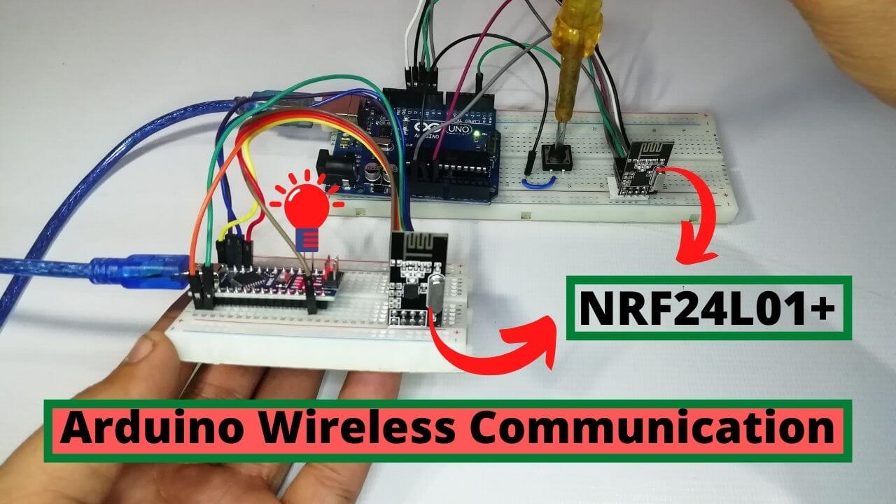
Today, we are going to look at something simple but useful. I am going to show you how you can send data wirelessly from one Arduino board to another using some very common wireless RF modules. Yes, I am talking about Arduino Wireless Communication using the NRF24L01 Transceiver Module.
These modules are the simplest ones you could use to add wireless capability to all your projects. They are none other than the NRF24L01 Transceiver Module. Basically, you can make more interesting projects including home automation, robotics, game controllers, etc. using these modules.
Table of contents
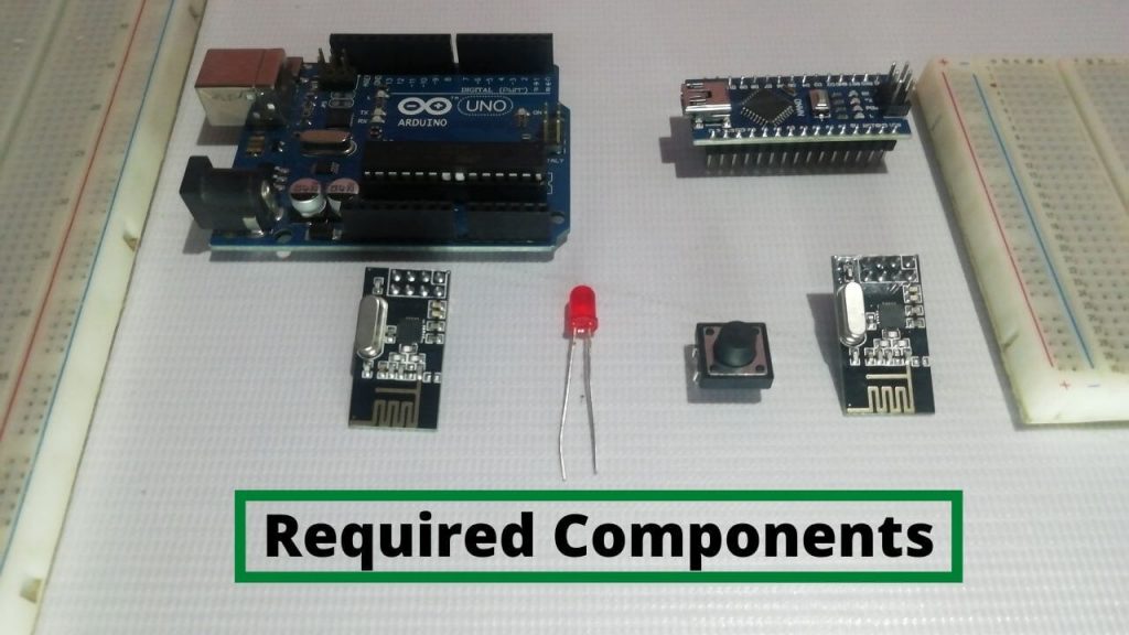
Components Required
The components required for Arduino Wireless Communication are listed below with their links:
| S.N | Components Name | Description | Quantity | |
|---|---|---|---|---|
| 1 | Arduino UNO | ARDUINO UNO R3 | 1 | https://amzn.to/2L0iZf2 |
| 2 | Arduino Nano | Arduino Nano R3 | 1 | https://amzn.to/3swvBuO |
| 3 | NRF Module | NRF24L01 Module | 2 | https://amzn.to/38M3eld |
| 4 | Button Switch | Tactile Push Button | 1 | https://amzn.to/3uEPim6 |
| 5 | LED | 5mm Diffused Red LED | 1 | https://amzn.to/3sJ0I6J |
| 6 | Jumper Wires | Jumper Cables breadboard friendly | 15 | https://amzn.to/2JWSR44 |
| 7 | USB Type B Cable | USB Cord Cable for Arduino UNO | 1 | https://amzn.to/362fmNx |
NRF24L01 Module Overview
The modules themselves are extremely cost-effective and are available for much less than a dollar.
- The older version of this was called the NRF24L01 and it only supported data rates of 1 or 2 megabits per second.
- The newer version is called the NRF24L01+ and it can support an additional lower data rate of 250kbps.
The lower data rate does consume slightly less current and I also think that it will be less disturbance in interference compared to higher data rates as it will not use as much bandwidth.
Hardware Overview of nRF24L01+ Wireless module
These modules come in different forms but the most popular are the two that I have shown below.
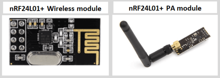
The first module comes with a PCB antenna so it is small and compact in size. This module is great for projects in a compact size. However, due to the antenna onboard, it has a short transmission range which makes it unsuitable in certain applications. This module has a transmission range of about 100 meters.
The second version has an external IPX antenna and is designed with a power amplifier. It has an RFX2401C range extender chip that allows the module to have a wide transmission range of up to 1Km.
Pinout for the nRF24L01+ transceiver module
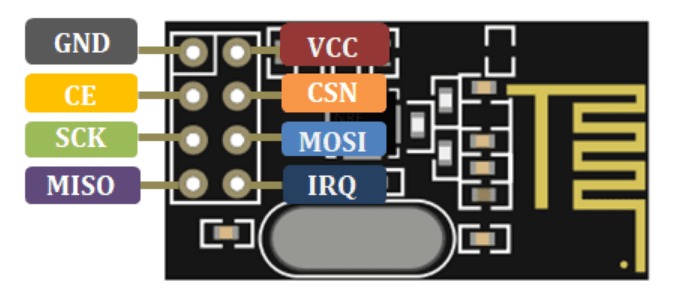
| GND | Ground pin |
| VCC | The power supply for the module |
| CE | Chip Enable |
| CSN/SCK | Chip Select Not/Serial Clock for accepting clock pulses |
| MOSI | Master In Slave Out |
| MISO | SPI output |
| IRQ | This is an interrupt pin |
Previous Related Arduino Tutorials:
- Send DS18B20 Temperature data over BLE using NRF24L01 & Arduino
- NRF24L01 as BLE Module with Arduino
- LoRa Based Wireless Weather Station using Arduino & ESP32
- Interfacing DHT11 Humidity and Temperature Sensor with Arduino & LCD
- BMP280 Based IoT Weather Station using ESP8266 & OLED Display
Interfacing NRF24L01 Transceiver Module with Arduino
In order to get this working, we need two NRF24L01+ modules, we will also need two Arduino boards and I will be using Arduino UNO and Arduino Nano.
The NRF24L01 module needs to be powered with 3.3V and it uses SPI for communication. This means that we need 4 additional pins for communication. Finally, we have the CE pin which is used to activate the transmitting or receiving mode bringing the total to 7 Pins.
| S.N | NRF24L01 Module | Arduino UNO |
| 1 | VCC | 3.3V |
| 2 | GND | GND |
| 3 | CE | Pin 9 |
| 4 | SCN/CSN | Pin 10 |
| 5 | SCK | Pin 13 |
| 6 | MOSI | Pin 11 |
| 7 | MISO | Pin 12 |
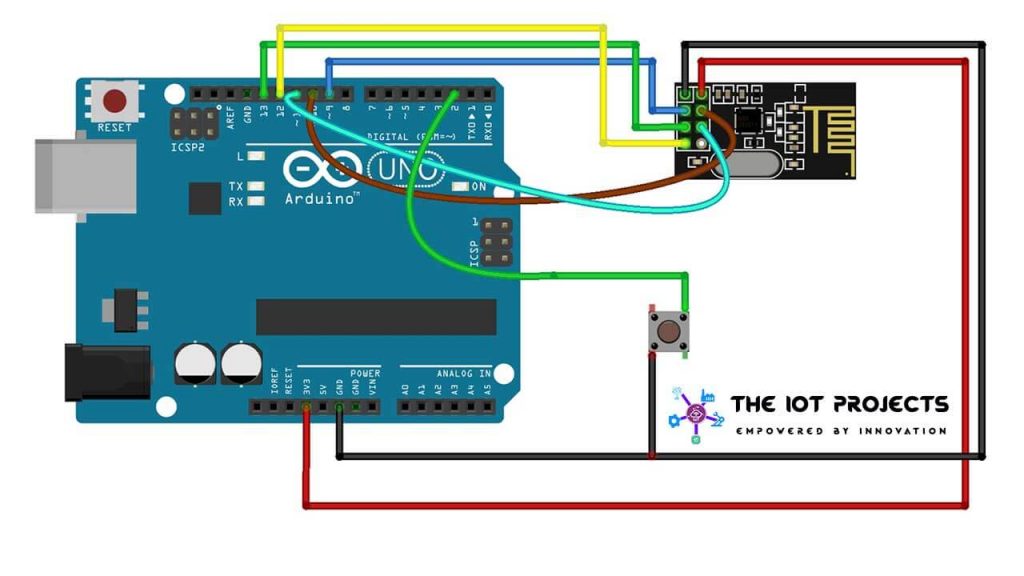
On the transmitter side, I am going to add a switch to Pin 2, such that it will be pulled LOW when the switch is pressed.
| S.N | NRF24L01 Module | Arduino Nano |
| 1 | VCC | 3.3V |
| 2 | GND | GND |
| 3 | CE | Pin 9 |
| 4 | SCN/CSN | Pin 10 |
| 5 | SCK | Pin 13 |
| 6 | MOSI | Pin 11 |
| 7 | MISO | Pin 12 |
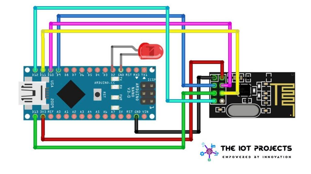
On the receiver, I will connect an LED to Pin 2.
You could select any other pin that you like. This is the reference wiring diagram that you can use.
Assembling the components
You cannot use the modules with a breadboard because the pin spacing is not enough to place it in the middle and if you place it anywhere else, then you will end up shorting the pins.
This means that you either have to design a custom PCB or use some jumper cables. I have assembled it with jumper cables but you can also design and order your own custom PCB from PCBWay.com. If you don’t have proper knowledge of Design. Visit the link for PCB Layout and Design. PCBWay is Partnered with quality service providers to offer design services. They use different PCB design software to meet your needs:
- Altium Designer
- Cadence Orcad or Allegro
- Eagle
- KiCAD etc.
They provide very high-level PCB design files and full 3D CAD design output capabilities.
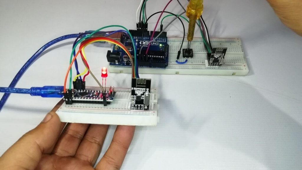
For a demonstration, I have connected the NRF24L01 Transceiver module with jumper cables. So here’s an example of how I’ve connected the Arduino Nano board to the NRF module.
Programming NRF24L01 Transceiver Module with Arduino
For this, we will need to install a library, so use the tools menu to open up the library manager and then type in NRF24. Select this library by TMRh20 and install it.
Now, you can use the file menu to explore the example sketches but these are a little complicated. You can copy the sketches from below in the Arduino IDE.
Arduino & NRF24L01 Transmitter Code
 #include "nRF24L01.h" //NRF24L01 library created by TMRh20 https://github.com/TMRh20/RF24
 #include "RF24.h"
 #include "SPI.h"
 #define SwitchPin 2
 int SentMessage[1] = {000};
 RF24 radio(9, 10); // NRF24L01 used SPI pins + Pin 9 and 10 on the NANO
 const uint64_t pipe = 0xE6E6E6E6E6E6; // Needs to be the same for communicating between 2 NRF24L01
 void setup()
 {
   pinMode(SwitchPin, INPUT_PULLUP);
   digitalWrite(SwitchPin, HIGH);
 radio.begin(); // Start the NRF24L01
   radio.openWritingPipe(pipe); // Get NRF24L01 ready to transmit
 }
 void loop()
 {
   if (digitalRead(SwitchPin) == LOW)    // If switch is pressed
   {
     SentMessage[0] = 111;
     radio.write(SentMessage, 1);      // Send pressed data to NRF24L01
   }
   else
   {
     SentMessage[0] = 000;
     radio.write(SentMessage, 1);      // Send idle data to NRF24L01
   }
 }
Let’s start with the transmitter program code Explanation.
const uint64_t pipe = 0xE6E6E6E6E6E6; // Needs to be the same for communicating between 2 NRF24L01All we are doing here is assigning an address to the module and we will have to use the same address for the receiver. This is how the RF modules know who they have to communicate with.
radio.begin(); // Start the NRF24L01
   radio.openWritingPipe(pipe); // Get NRF24L01 ready to transmit
We then initialize the module and get it ready for transmission.
{
   if (digitalRead(SwitchPin) == LOW)    // If switch is pressed
   {
     SentMessage[0] = 111;
     radio.write(SentMessage, 1);      // Send pressed data to NRF24L01
   }
   else
   {
     SentMessage[0] = 000;
     radio.write(SentMessage, 1);      // Send idle data to NRF24L01
   }
If the switch is pressed, then the pin will go LOW and we then send the message 111, or else, we send the message 000. You can obviously change the value that is being sent to suit your requirements.
Now, select the correct board and COM port and then upload this sketch to the Arduino transmitter node.
Once that is done, open up the sketch for the receiver.
Arduino & NRF24L01 Receiver Code
 #include "nRF24L01.h" // NRF24L01 library created by TMRh20 https://github.com/TMRh20/RF24
 #include "RF24.h"
 #include "SPI.h"
 #define LED_PIN 2
 int ReceivedMessage[1] = {000}; // Used to store value received by the NRF24L01
 RF24 radio(9, 10); // NRF24L01 SPI pins. Pin 9 and 10 on the Nano
 const uint64_t pipe = 0xE6E6E6E6E6E6; // Needs to be the same for communicating between 2 NRF24L01
 void setup(void)
 {
   radio.begin(); // Start the NRF24L01
 radio.openReadingPipe(1, pipe); // Get NRF24L01 ready to receive
 radio.startListening(); // Listen to see if information received
 pinMode(LED_PIN, OUTPUT);
 }
 void loop(void)
 {
   while (radio.available())
   {
     radio.read(ReceivedMessage, 1); // Read information from the NRF24L01
 if (ReceivedMessage[0] == 111) // Indicates switch is pressed {   digitalWrite(LED_PIN, HIGH); } else {   digitalWrite(LED_PIN, LOW); } delay(2);
 }
 }
Make sure you use the exact same address that you used in the transmitter sketch.
const uint64_t pipe = 0xE6E6E6E6E6E6; // Needs to be the same for communicating between 2 NRF24L01All we are doing here is getting the module ready to receive data and we then start listening to the data that is being sent to it.
radio.begin(); // Start the NRF24L01
 radio.openReadingPipe(1, pipe); // Get NRF24L01 ready to receive
 radio.startListening(); // Listen to see if information received
 pinMode(LED_PIN, OUTPUT);
If we receive the number 111 then we know that the switch was being pressed and so we switch ON the LED.
radio.read(ReceivedMessage, 1); // Read information from the NRF24L01
 if (ReceivedMessage[0] == 111) // Indicates switch is pressed {   digitalWrite(LED_PIN, HIGH);
In all other cases, we switch the LED OFF.
else
     {
       digitalWrite(LED_PIN, LOW);
     }
Again, select the correct board, COM port, and then upload this Arduino Receiver Node.
Demonstration of Basic Arduino Wireless Communication
It’s now time to test it out. We have the transmitter on one side with the receiver on the other. When we press the switch, you will notice that the LED will light up instantly. The video demonstration of Arduino Wireless Communication using NRF24L01 Transceiver Module is attached below.
Conclusion
That is the quickest way to get Arduino Wireless Communication using the NRF24L01 Transceiver Module. You can extend this principle to do just about anything that you want. If you have any queries don’t hesitate to share in the comment below.


When I upload the code to Arduino, do I need to upload the library along with it?
Reply please
No. Arduino IDE will compile code using those library.
Thank you for your kind information 🙏
Where can I purchase PCB for this project