Audio Spectrum Visualizer Using Arduino & Matrix Display
Music/Audio Visualizer Using Arduino & MAX7219 Dot Matrix Display
Overview: Audio/Music Visualizer using Arduino
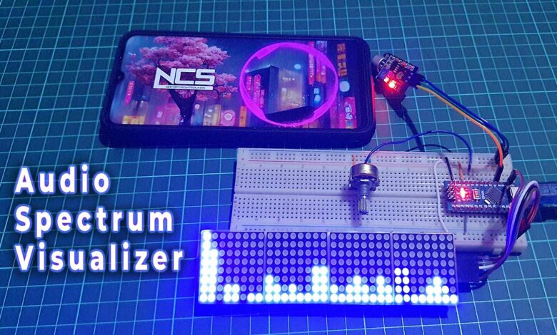
Today we will learn how to create an Audio Spectrum Visualizer using an Arduino and a MAX7219 Matrix Display. In this project, we’ll show you how to build a circuit that can visualize the frequency spectrum of both periodic and speech signals in real-time, and display it on an LED dot matrix display.
Most musical concerts, festivals, and nightclubs commonly have fancy disco lights that sync with the rhythm of the music. Ideas came into my mind constructing my own Audio Spectrum Visualizer that would respond to audio or music. So. I can use it on my old music system. To achieve this goal, I utilized an Arduino Nano as the project’s core component, in addition to a 32×8 Dot Matrix Display and a sound sensor.
The Dot Matrix Display’s individual LEDs will respond in accordance with the Analog audio signals transmitted to the Arduino Nano via the sound sensor, which is linked to its Analog pin. By utilizing the built-in ADC (Analog to Digital converter) input pin, the Arduino can obtain the Analog audio signals from the sound sensor and convert them into digital signals.
Also Read: Smart Notice Board with ESP8266 & Dot Matrix LED Display
Components Required
Now, let’s go over the components you’ll need to build this project. You’ll need an Arduino Nano, a MAX7219 Dot Matrix Display, a Sound Sensor, a Potentiometer, a Breadboard, and some Jumper Wires. You can easily buy them from below.
| S.N | COMPONENTS NAME | QUANTITY | PURCHASE LINKS |
|---|---|---|---|
| 1 | Arduino Nano | 1 | Amazon | AliExpress |
| 2 | MAX7219 Dot Matrix LED Display | 1 | Amazon | AliExpress |
| 3 | Sound Sensor | 1 | Amazon | AliExpress |
| 4 | 10k Potentiometer | 1 | Amazon | AliExpress |
| 5 | Breadboard | 1 | Amazon | AliExpress |
| 6 | Jumper Cables | 10 | Amazon | AliExpress |
MAX7219 Dot Matrix Display
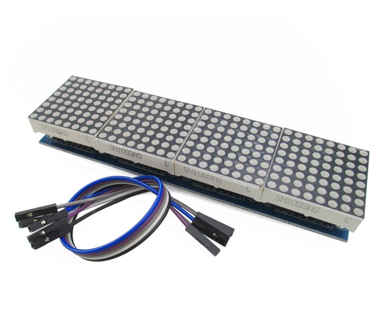
Dot Matrix Displays come in a variety of colors and dimensions, including single-color, dual-color, and RGB color options. Available sizes include 5×7, 8×8, 16×16, 8×32, 32×32, and more.
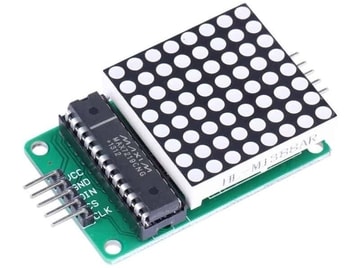
The 8×32 LED Matrix Display consists of four separate Matrix Displays that are internally linked. Each module is equipped with the Maxim MAX7219 chip. It can be connected using the same power and data connection, allowing for easy replacement of any damaged single displays.
MAX7219 LED Driver Chip
These Matrix Displays can be driven in two ways: parallel or serial. The parallel method involves sending parallel data to each row or column. while the serial method uses an IC to convert serial data into parallel data.
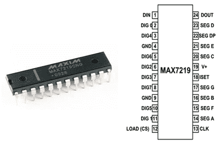
The MAX7219 is a common cathode display driver with serial input and parallel output. It is used to connect microprocessors and microcontrollers to 64 individual LEDs. Including the 8×8 LED matrix that is connected to it. The MAX7219 receives data input from the Arduino board.
Audio Spectrum Visualizer Circuit Connection
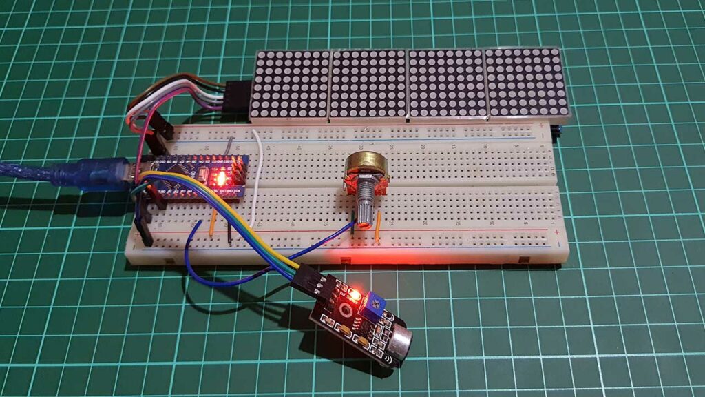
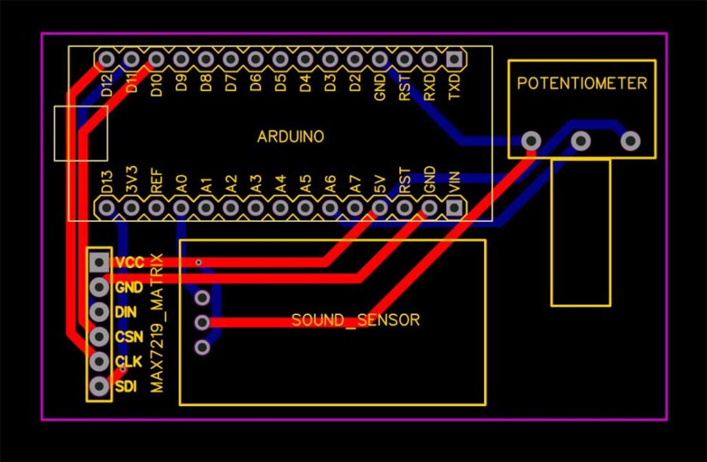
Once you have all the components, you’ll need to connect them together as shown in the circuit diagram.
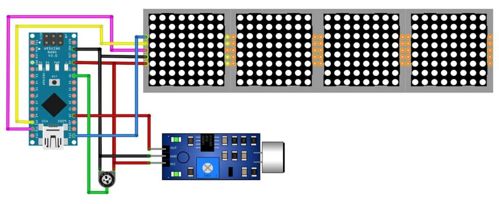
Both the Dot Matrix Display and the Sound Sensor are powered by the 5V output pin of the Arduino Nano. But you can also use an external power source for a better current supply. The Analog data pin of the Sound Sensor is connected to the A0 pin of the Arduino Nano. The DIN, CS, and CLK pins of the Dot Matrix Display are connected to the D11, D10, and D13 pins of the Arduino Nano. (Optional) a 10k potentiometer can be attached to pin A6 to control sensitivity.
Project PCB Gerber File & PCB Ordering Online
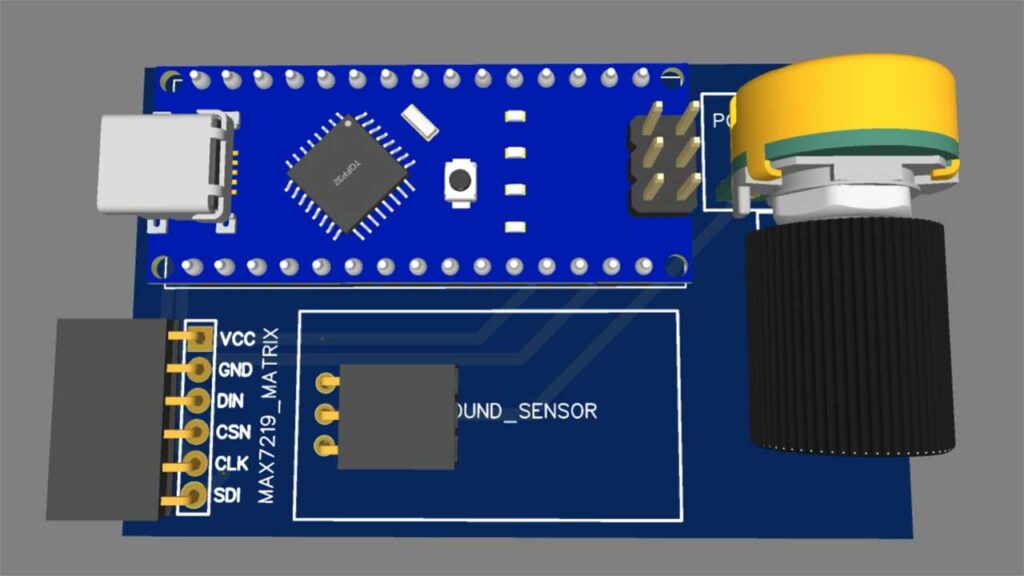
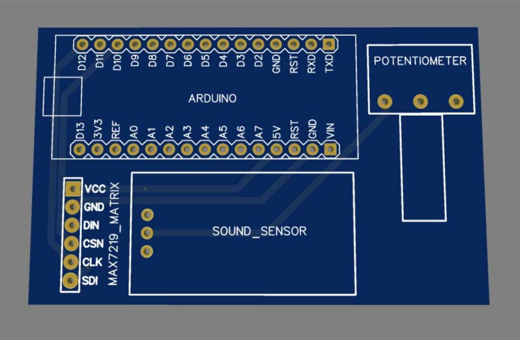
If you don’t want to assemble the circuit on a zero PCB and you want PCB for the project, then here is the PCB for you. The PCB Board for this project looks something like below.
The Gerber File for the PCB is given below. You can simply download the Gerber File and order the PCB from PCBWay.com.
Now you can visit the PCBWay official website by clicking here: PCBWay.com. So you will be directed to the PCBWay website.

You can now upload the Gerber File to the Website and place an order. The PCB quality is superb & high standard. That is why most people trust PCBWay for PCB & PCBA Services. PCBWay is a leading manufacturer of high-quality PCBs and offers a wide range of services, including PCB fabrication, assembly, and components sourcing.
Arduino Program Code
Next, you must copy the program code from below and install the required libraries. The program code uses two libraries – one for the Arduino FFT and the other for the MAX7219 module. The code is well-documented, so you can easily understand how it works.
#include <arduinoFFT.h>
#include <MD_MAX72xx.h>
#include <SPI.h>

MD_MAX72XX disp = MD_MAX72XX(MD_MAX72XX::FC16_HW, 10, 4);

arduinoFFT FFT = arduinoFFT();

double realComponent[64];
double imagComponent[64];
int spectralHeight[] = {0b00000000, 0b10000000, 0b11000000,


                        0b11100000, 0b11110000, 0b11111000,


                        0b11111100, 0b11111110, 0b11111111
                       };

int index, c, value;

void setup()

{

  disp.begin();

  Serial.begin(9600);

}

void loop()

{

  int sensitivity = map(analogRead(A6), 0, 1023, 50, 100);
  Serial.println (analogRead(A6));
  for (int i = 0; i < 64; i++)

  {

    realComponent[i] = analogRead(A0) / sensitivity;
    imagComponent[i] = 0;

  }

  FFT.Windowing(realComponent, 64, FFT_WIN_TYP_HAMMING, FFT_FORWARD);
  FFT.Compute(realComponent, imagComponent, 64, FFT_FORWARD);
  FFT.ComplexToMagnitude(realComponent, imagComponent, 64);

  for (int i = 0; i < 32; i++)

  {

    realComponent[i] = constrain(realComponent[i], 0, 80);
    realComponent[i] = map(realComponent[i], 0, 80, 0, 8);
    index = realComponent[i];
    value = spectralHeight[index];

    c = 31 - i;
    disp.setColumn(c, value);

  }

}
The program code uses the FFT algorithm to compute the 64 spectral components for the real and imaginary parts of the spectrum. Once we have the 64 samples, we apply the complex-to-magnitude function to compute the magnitude of the spectral elements. Then, we use a for loop to cover the 32 columns of the MAX7219 module and sketch the column patterns based on the magnitude values of the spectral elements.
Uploading Code to Arduino Nano
Once you’ve installed the required libraries and made any necessary modifications to the program code. You can upload it to the Arduino Nano using the Arduino IDE. To do that select the correct board and its COM port from the tools menu.
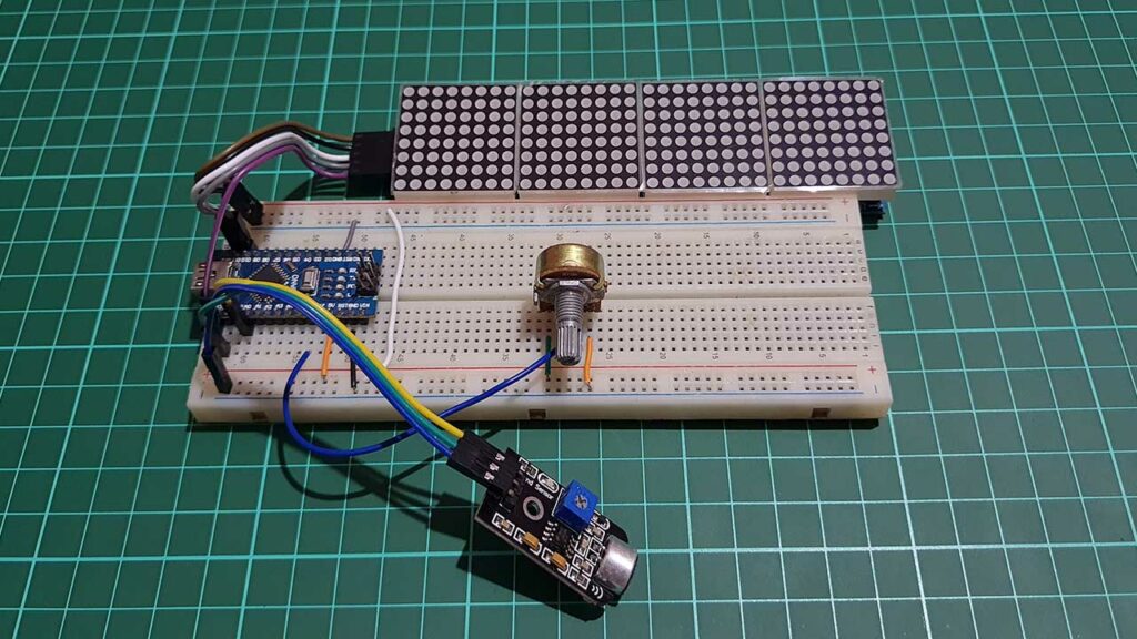
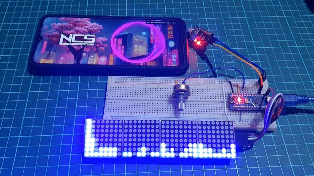
Testing & Demo: Audio Spectrum Visualizer Using Arduino
Now that you’ve built the circuit and uploaded the program code. It’s time to test it out. You can apply periodic signals such as a square waveform or speech signals as input to the circuit. Then observe the spectral components on the MAX7219 Matrix Display. We’ll demonstrate both types of inputs in the video, so you can see how it works in action.
Application of this project
So, what are some possible applications of the Audio Spectrum Visualizer project? You could use it as a visualizer for music or speech signals, or as a tool for analyzing the frequency content of different sounds. It’s a fun and educational project that can teach you a lot about signal processing and microcontroller programming.
Conclusion
That’s it for our tutorial on how to create an Audio Spectrum Visualizer using an Arduino and a MAX7219 Matrix Display. We hope you found it helpful and informative. Feel free to comment down below.