IoT Smoke & Gas Detector using ESP8266 & Blynk
MQ2 Sensor Based IoT Smoke Detector using ESP8266
Today we will make an IoT based smoke and gas detector using an MQ2 Sensor, ESP8266 microcontroller, and Blynk IoT Cloud. We have used the MQ2 Gas sensor module to detect Smoke, LPG, and carbon monoxide concentrations present in Air. MQ2 is a versatile sensor that can detect LPG, smoke, alcohol, propane, hydrogen, methane, carbon monoxide, etc. This makes the MQ2 Gas Sensor Module an excellent choice for building an indoor air quality monitoring system, a breathalyzer, or an early fire detection system.
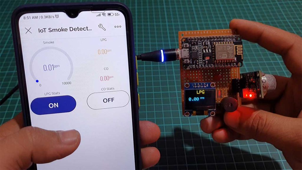
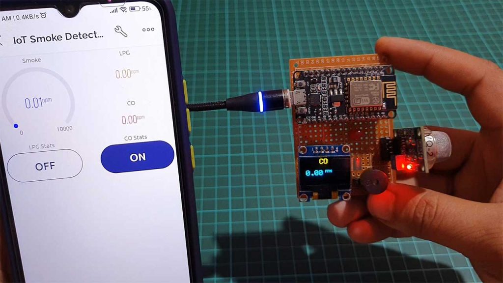
This project has an OLED display to Display the Smoke, LPG, and Carbon Monoxide concentrations in PPM. The same data can be monitored on an Android app as well as Web Dashboard. We have two buttons that help to switch the monitoring screen between Smoke, LPG, and Carbon monoxide.
Overview: IoT Smoke & Gas Detector
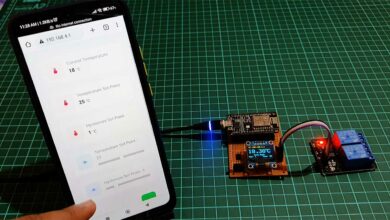
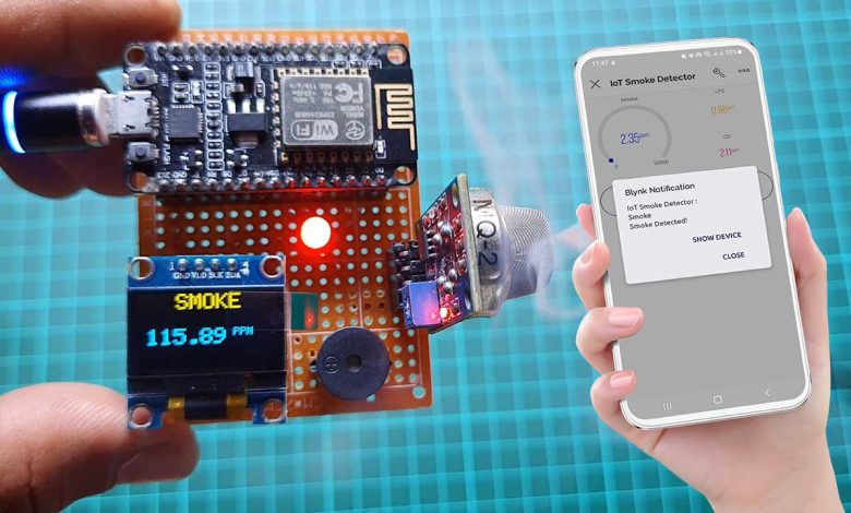
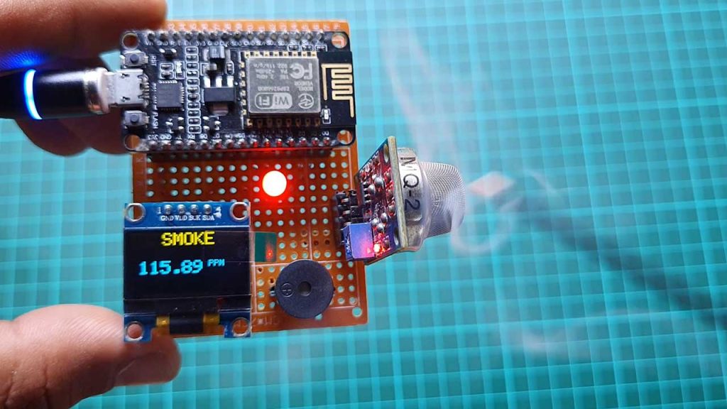
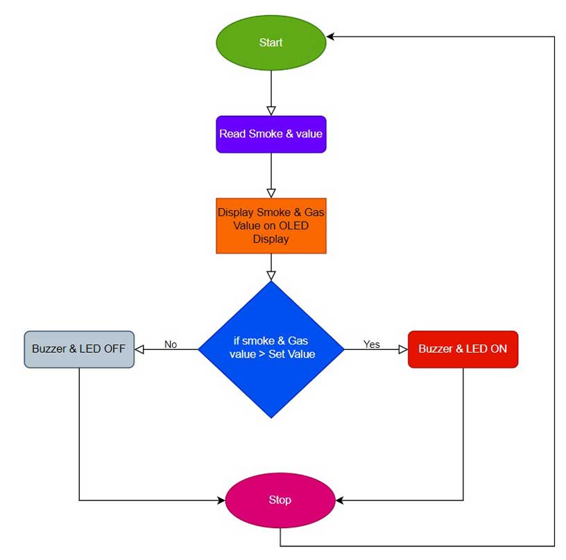
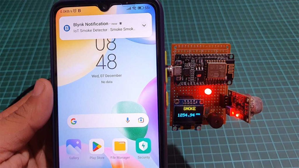
First, let’s see how this project works. The sensor detects smoke, LPG, and Carbon Monoxide values and sends them to ESP8266 Microcontroller. Then it processes these values and displays these values on the OLED display as well as on the Blynk IoT Platform. It also checks if these values are above the safe level then it sends a notification to the Mobile phone as well as buzzer starts alarming with a flashing LED.
It is a very easy-to-build but very worthwhile project. So without further Ado let’s make this project.
Components Required
These are all the components that are required for making an IoT Based Smoke & Gas Leakage Detector using ESP8266. You can easily purchase them from the Amazon links provided below:
| S.N | Components Name | Quantity | |
|---|---|---|---|
| 1 | NodeMCU ESP8266 | 1 | https://amzn.to/3WaECc2 |
| 2 | MQ2 Sensor | 1 | https://amzn.to/3FdD2QS |
| 3 | 0.96" I2C OLED Display | 1 | https://amzn.to/3EV50PS |
| 4 | Buzzer | 1 | https://amzn.to/3ipsO6X |
| 5 | 5mm LED | 1 | https://amzn.to/3Fg5LV3 |
| 6 | Zero PCB board | 1 | https://amzn.to/3UmLt0B |
Circuit Diagram: IoT Gas & Smoke Detector
This is the circuit diagram of the IoT Smoke & Gas Leakage Detector using ESP8266.
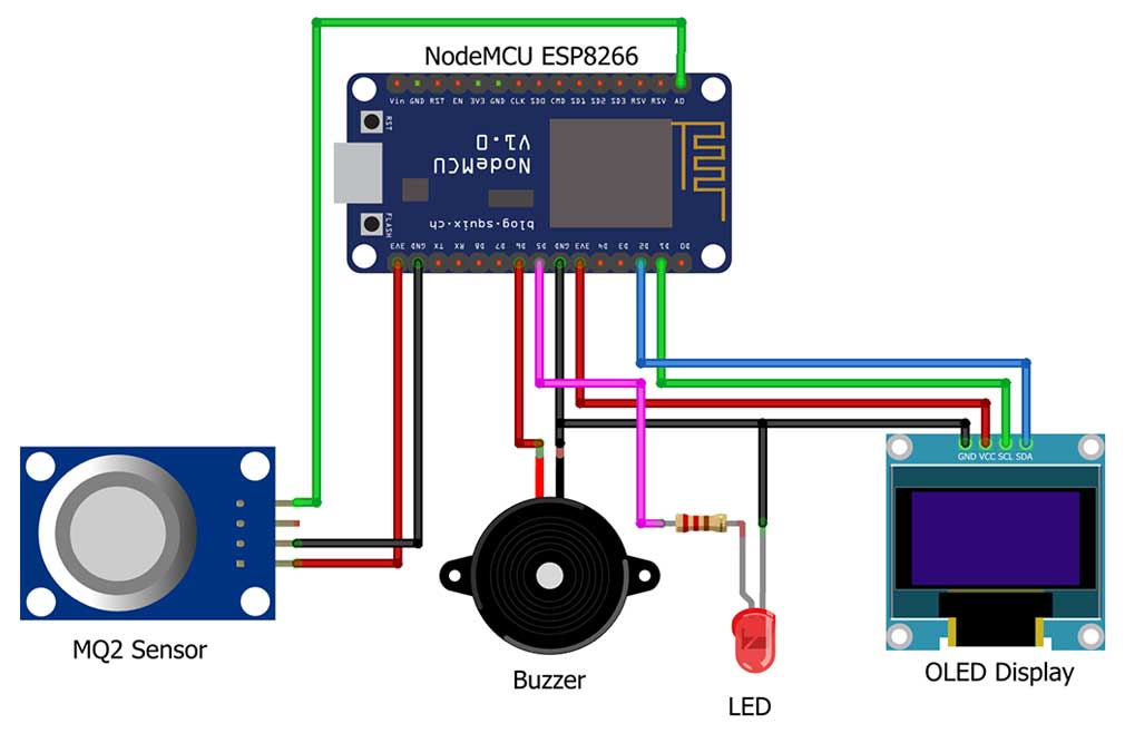
Here I have interfaced the MQ2 sensor Analog Pin A0 pin with the A0 pin of ESP8266. VCC and GND are connected to the 3.3 Volt and GND pins of ESP8266 respectively. After that, I connected the I2C OLED VCC pin to the 3.3V pin of NodeMCU and its ground pin to the ground. Its SCL and SDA pins to the D1 and D2 pins of NodeMCU. After that, I connected an LED anode pin to the D5 pin and its cathode pin to the ground. Lastly, I connected the buzzer’s positive pin to the D6 pin of the NodeMCU and its negative pin to the Ground pin.
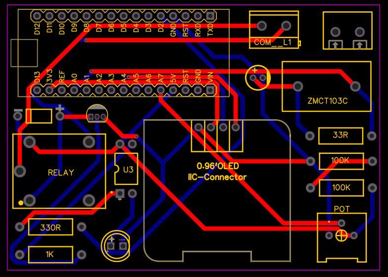
Project PCB Gerber File & PCB Ordering Online
To implement this whole system you will need a PCB. You can use breadboard assembly just to test this project. So, to make your work easier I have designed a custom PCB for this project. You can directly order your PCB from PCBWay.com.
Now you can visit the PCBWay official website by clicking here: PCBWay.com. So you will be directed to the PCBWay website.
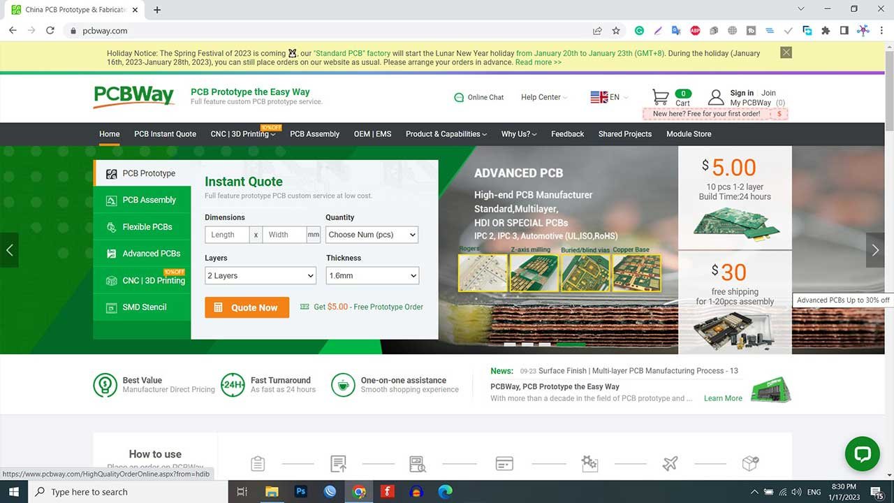
You can now upload the Gerber File to the Website and place an order. The PCB quality is superb & high standard. That is why most people trust PCBWay for PCB & PCBA Services. PCBWay is a leading manufacturer of high-quality PCBs and offers a wide range of services, including PCB fabrication, assembly, and components sourcing.
So I have done all the connections. Now let’s set up the Blynk IoT Platform to test this project.
Setting up Blynk IoT Dashboard
In order to monitor the Smoke, LPG, and CO Data on Blynk IoT Server, you first need to set up the Blynk IoT Cloud dashboard. To set up the Blynk Server, visit https://blynk.cloud/. Create an account or simply sign in if you created the account earlier.
Also Read: Home Automation using ESP32 & Blynk 2.0
Creating Blynk New template
A template is a project in which we can create a web and mobile dashboard for specific hardware. In our case, it’s a Smoke & Gas Detection System. For creating a project, first, you have to click on the New Template.
- Enter a template name. I am giving it a “Smoke Detector”.
- Select the hardware board (ESP8266).
- The connection type will be wifi.
- You can add a description of your project if required.
- Click on Done.
- Now the template is created.
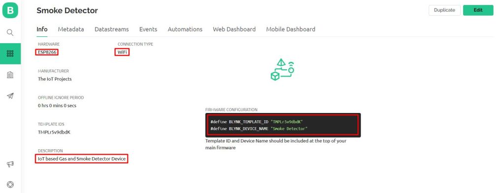
Here are two important things that you should remember one is the template id and another one is the device name which is required at the time of programming.
Creating New Blynk Datastream
In our project, we are monitoring five parameters. So you can give names to those parameters. In my case, Smoke, LPG, CO, Button 1, and Button 2 are five DataStream.
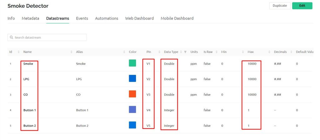
I have selected V1 to V5 respectively for our DataStreams for the Live Monitoring. The Variable data type is Double for all the variables except Button 1 and Button 2 which is an Integer type. The maximum value for smoke, LPG, and CO is 10000 and the default value is set to zero for all data streams.
Creating Events on Blynk for Notification Alerts
Events are used for notification alert systems. So, here I am creating events to monitor Smoke. If the smoke value reaches above the threshold value an event is triggered and a notification is sent to your mobile phone.
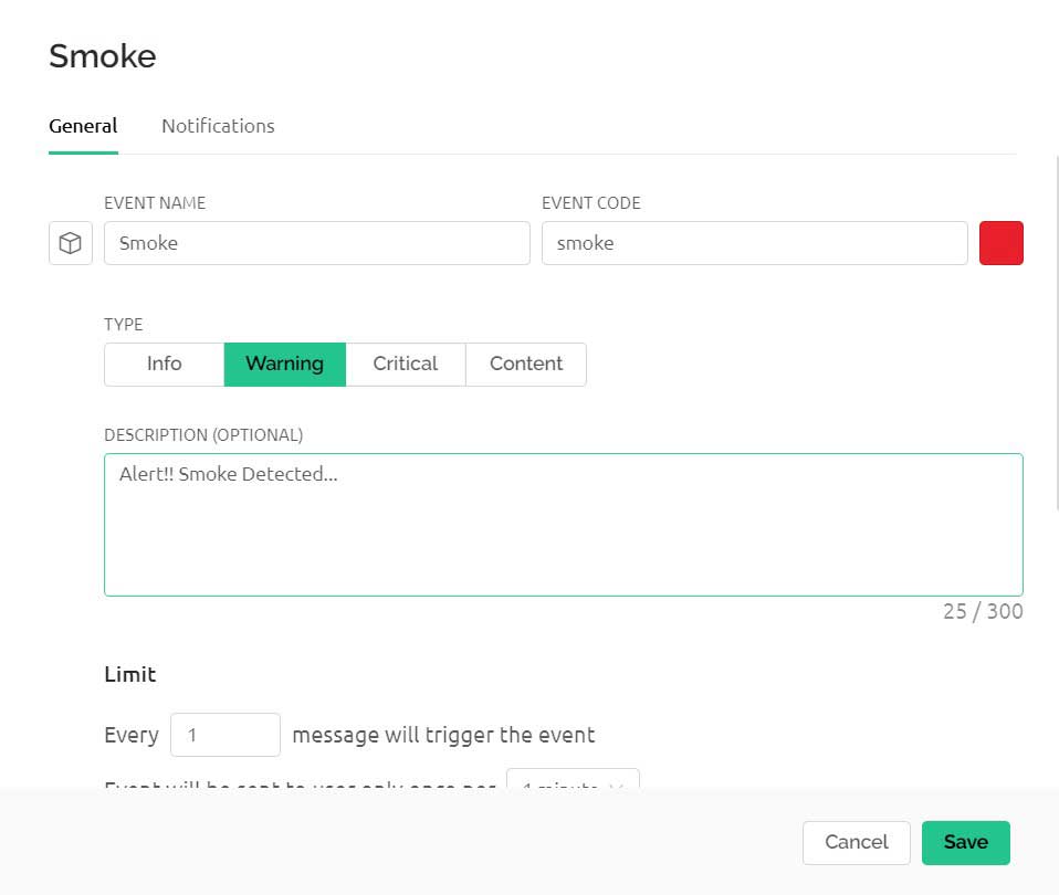
So to create an event:
- Click on the add event.
- Enter the event Name. For me, it’s “smoke“
- Choose your event color. I am selecting Red.
- Select the type of event. I am choosing Warning.
- Enter the description of your event.
- then choose your limit to once every 1 minute.
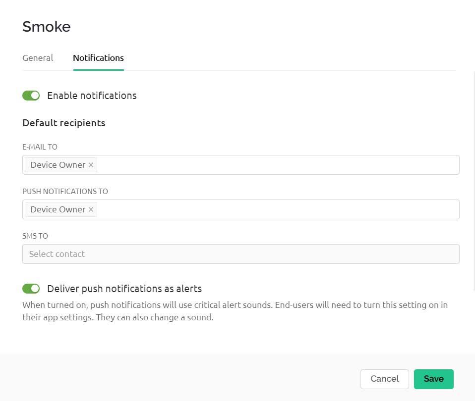
- Now go to the notification tab then enable notification.
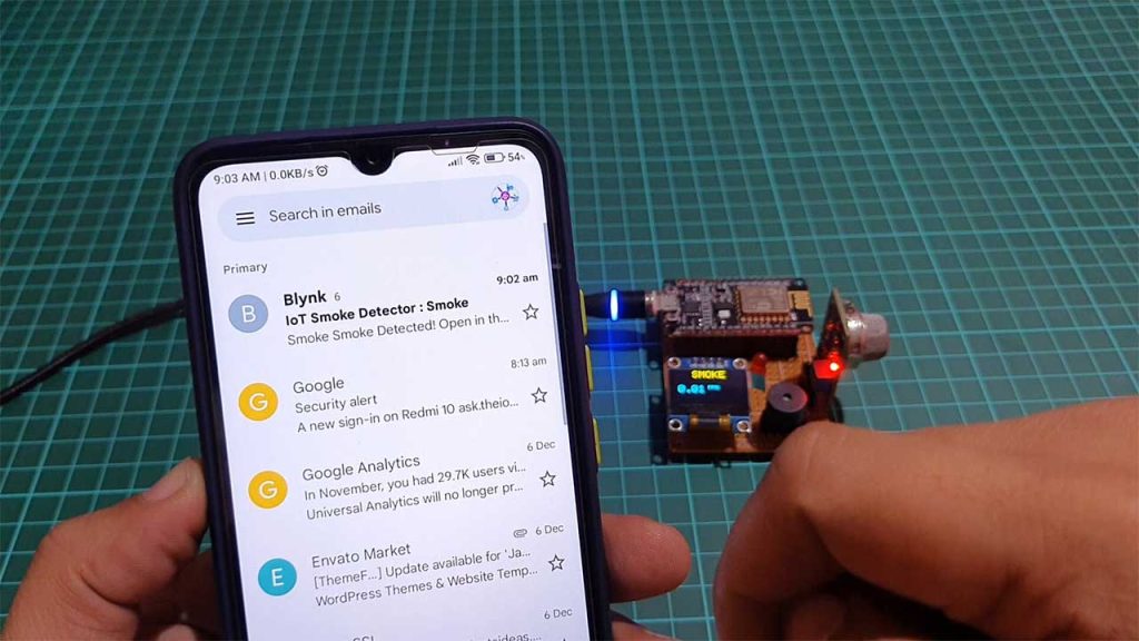
- Set Email and Push Notifications to the device owner.
- Also, turn on Deliver push notifications as alerts
- Click on save.
So, we have successfully created our first events.
Design the Blynk 2.0 Web Dashboard
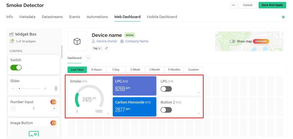
After that move on to the web dashboard. In this section, you will be able to see some widgets for making your cool-looking web dashboard. But all the widgets are not free. You will get it all if you purchase their upgrade plan.
For showing the value of Smoke I have selected Gauge. Label widget for LPG and CO value. Similarly, switch widgets for buttons. But, you can choose any widget according to your project. Now change the settings of the label. In settings, you have to give a name to the widget and you have to choose the data stream with which the widget will be connected. After setting up the widgets click on the save button to save the entire project. That’s all for setting up the Blynk IoT dashboard. We will set up the Blynk Mobile dashboard after uploading the program code.
Source Code/Program
Here is the source code for the IoT Smoke & Gas Detector System using ESP8266. But, You need to install these libraries in your Arduino IDE before uploading the program code.
Now open your Arduino IDE. Go to File >> Examples >> Blynk >> Blynk.Edgent >> ESP8266_Edgent. Just copy the code provided below and paste it into your Arduino IDE ESP8266_Edgent page. Do not make any changes to other files. You need to replace your Blynk Template ID and Blynk Device Name which is available in the blynk template. Simply after making the necessary changes upload the code to NodeMCU ESP8266 12E Board.
// Fill-in information from your Blynk Template here
#define BLYNK_TEMPLATE_ID "TMPLr5v9dbdK"
#define BLYNK_DEVICE_NAME "Smoke Detector"
#define BLYNK_FIRMWARE_VERSION "0.1.0"
#define BLYNK_PRINT Serial
//#define BLYNK_DEBUG
#define APP_DEBUG
// Uncomment your board, or configure a custom board in Settings.h
//#define USE_SPARKFUN_BLYNK_BOARD
#define USE_NODE_MCU_BOARD
//#define USE_WITTY_CLOUD_BOARD
//#define USE_WEMOS_D1_MINI
#include "BlynkEdgent.h"
#include <MQ2.h>
#include <SPI.h>
#include <Wire.h>
#include <Adafruit_GFX.h>
#include <Adafruit_SSD1306.h>
#define SCREEN_WIDTH 128 // OLED display width, in pixels
#define SCREEN_HEIGHT 64 // OLED display height, in pixels
#define OLED_RESET -1 // Reset pin # (or -1 if sharing Arduino reset pin)
#define SCREEN_ADDRESS 0x3C ///< See datasheet for Address; 0x3D for 128x64, 0x3C for 128x32
Adafruit_SSD1306 display(SCREEN_WIDTH, SCREEN_HEIGHT, &Wire, OLED_RESET);
#define BUZZ 12 //D6
#define LED 14 //D5
//change this with the pin that you use
int pin = A0;
float lpg, co, smoke;
MQ2 mq2(pin);
int button1 = 0;
int button2 = 0;
SimpleTimer timer;
void setup()
{
Serial.begin(115200);
delay(100);
BlynkEdgent.begin();
pinMode(BUZZ, OUTPUT);
pinMode(LED, OUTPUT);
digitalWrite(BUZZ, LOW);
digitalWrite(LED, LOW);
// calibrate the device
mq2.begin();
// SSD1306_SWITCHCAPVCC = generate display voltage from 3.3V internally
if (!display.begin(SSD1306_SWITCHCAPVCC, SCREEN_ADDRESS)) {
Serial.println(F("SSD1306 allocation failed"));
for (;;); // Don't proceed, loop forever
}
delay(2000);
display.clearDisplay();
display.setTextSize(2);
display.setTextColor(SSD1306_WHITE); // Draw white text
display.setCursor(0, 0);
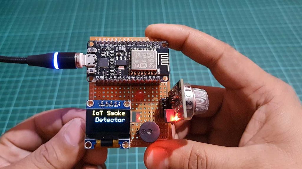
display.println(" IoT Smoke ");
display.setCursor(0, 20);
display.println(" Detector ");
display.display();
delay(1000);
timer.setInterval(1000L, sendSensorData);
}
void loop() {
timer.run(); // Initiates SimpleTimer
BlynkEdgent.run();
}
void sendSensorData()
{
float* values = mq2.read(true); //set it false if you don't want to print the values to the Serial
co = mq2.readCO();
smoke = mq2.readSmoke();
lpg = mq2.readLPG();
if (button1 == 1)
{
// display LPG
display.clearDisplay();
display.setTextSize(2);
display.setCursor(0, 0);
display.print(" LPG ");
display.setCursor(10, 30);
display.print(lpg);
display.setTextSize(1);
display.print(" PPM");
delay(5000);
display.display();
}
else if (button2 == 1)
{
// display CO
display.clearDisplay();
display.setTextSize(2);
display.setCursor(0, 0);
display.print(" CO ");
display.setCursor(10, 30);
display.print(co);
display.setTextSize(1);
display.print(" PPM");
delay(5000);
display.display();
}
else {
// display Smoke
display.clearDisplay();
display.setTextSize(2);
display.setCursor(0, 0);
display.print(" SMOKE ");
display.setCursor(10, 30);
display.print(smoke);
display.setTextSize(1);
display.print(" PPM");
delay(5000);
display.display();
}
Blynk.virtualWrite(V1, smoke);
Blynk.virtualWrite(V2, lpg);
Blynk.virtualWrite(V3, co);
if (smoke > 50 ) {
Blynk.logEvent("smoke", "Smoke Detected!");
digitalWrite(BUZZ, HIGH);
digitalWrite(LED, HIGH);
}
else {
digitalWrite(BUZZ, LOW);
digitalWrite(LED, LOW);
}
}
// in Blynk app writes values to the Virtual Pin 4
BLYNK_WRITE(V4)
{
button1 = param.asInt(); // assigning incoming value from pin V4 to a variable
}
// in Blynk app writes values to the Virtual Pin 5
BLYNK_WRITE(V5)
{
button2 = param.asInt(); // assigning incoming value from pin V5 to a variable
}Blynk IoT 2.0 Mobile App Setup
Download the blynk application into your mobile.
- New Blynk Mobile App (Android)
- New Blynk Mobile App (iOS)
After installing the application login into your account. Turn on the developer mode if it is not turned on by going into your profile.
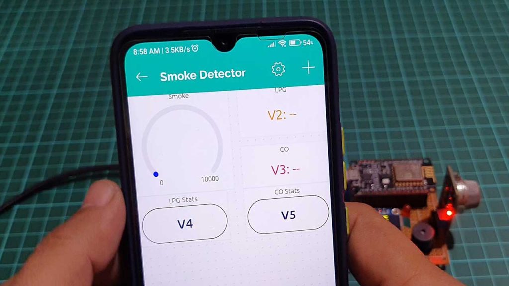
Now click on Smoke Detector Prototype then Click on plus icon to add different widgets. You can configure your Mobile dashboard as shown here. First Add Gauge Widget and Configure it for Smoke Datastream. Make some changes to its settings if required. Then add two Value display widget and configure them for LPG and CO as shown here. Finally add two buttons and configure them as switches with their respective datastreams.
Now Go back and add a device to this system.
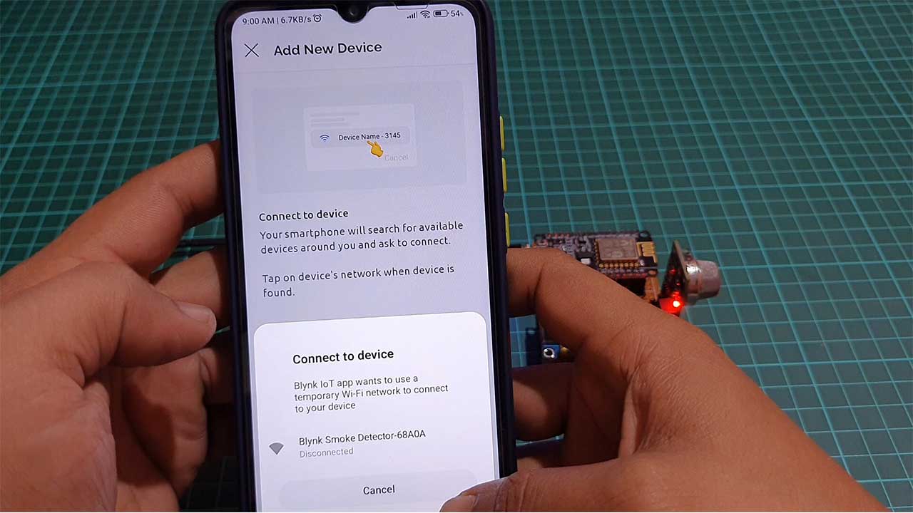
- Click on Add new device
- Click on Find devices nearby
- Now Click on Start
- Then click on continue
- Choose the wifi which is created by the NodeMCU “Blynk Smoke Detector”
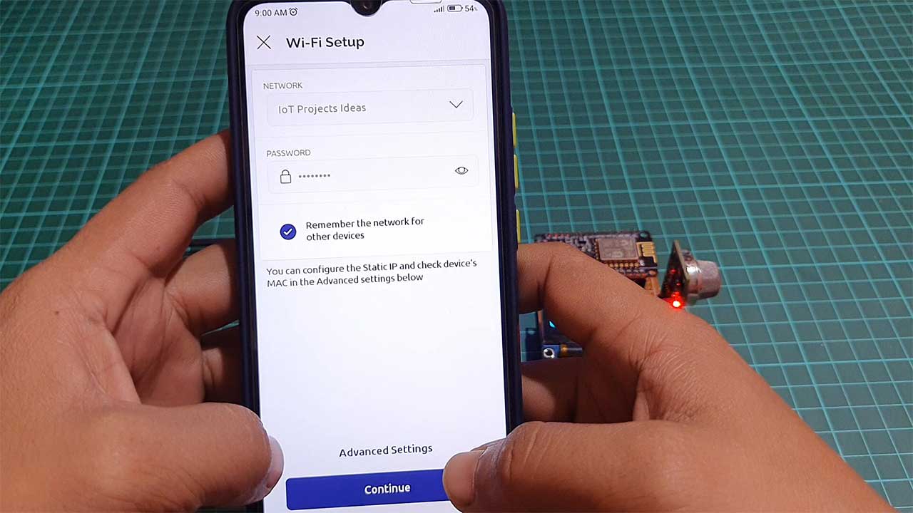
- Give the wifi credentials of the router with which you want to connect the NodeMCU
- Click on Continue
- Now the board will connect to the router if the given wifi credentials are true
- Provide your Device Name and click on Finish
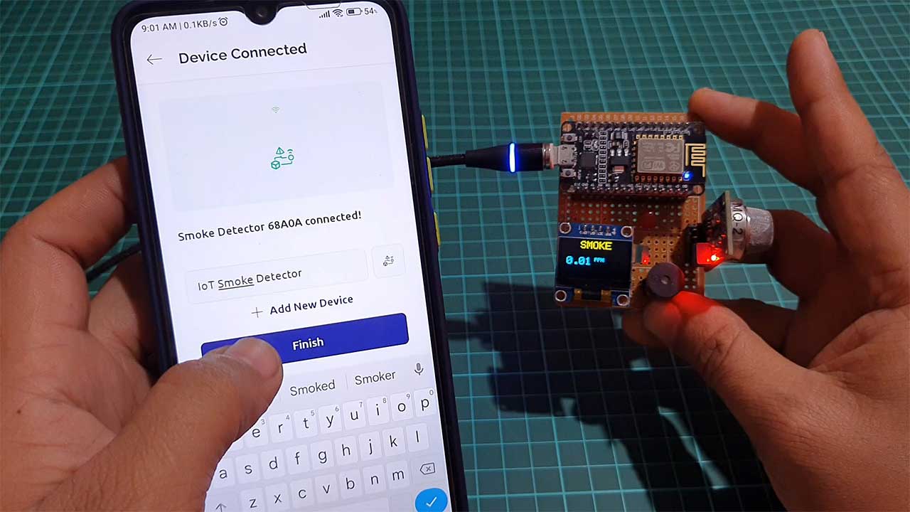
So, that’s all for the Mobile dashboard setup. Now you can see the data of your blynk device into your mobile app and in the web dashboard as well.
Testing: Smoke & Gas Detector using ESP8266 & Blynk IoT
Open the Serial Monitor after uploading the code. The ESP8266 will try connecting to the WiFi Network. Once it connects to the WiFi Network, it will display the Smoke, LPG, and Carbon Monoxide. Same data can be monitored through Blynk IoT Mobile App and Web Dashboard.
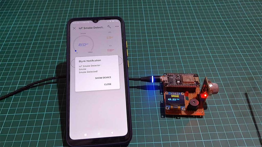
As soon as smoke reaches above threshold value a notification is sent to a mobile device. For demonstration, I’m using 50 PPM as a threshold value.
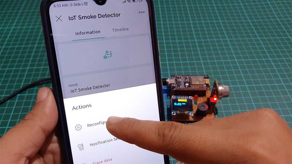
Reconfiguring WiFi credentials on device without hardcoding
To reconfigure the wifi credentials on the new blynk platform you don’t have to hardcode the device. Under device settings, choose the reconfigure device option to reconfigure your device to the new WiFi network.
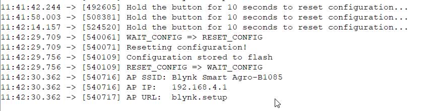
Alternatively, You can also press the flash button on NodeMCU for 10 seconds to erase WiFi credentials from EEPROM. Then you can reconfigure the wifi credentials again by adding it as a new device.
Video Tutorial & Guide
Conclusion
Alright, that’s all for the MQ2 Sensor Based IoT Smoke Detector using ESP8266 & Blynk IoT. This project is very helpful for monitoring our internal (home) environment wirelessly. The complete project details including device information purchase link source code and written guide are provided for you. I hope you enjoyed reading this article. In case you have any other questions you can comment in the comment section below.