IoT based Anemometer using ESP8266 & Arduino IoT Cloud
IoT based Wind Speed Meter using ESP8266
In this tutorial, we will make an IoT based Anemometer using ESP8266 & Arduino IoT Cloud. This is an IoT based wind speed meter using an NPN pulse output Anemometer sensor and Arduino IoT Cloud. The Anemometer sensor is a device used for measuring wind speed and direction. It is also a standard weather station instrument. So today you will learn to interface the Anemometer sensor with ESP8266 NodeMCU and OLED Display. The system uses NPN Pulse Output Anemometer to calculate wind speed in meters per second. Then ESP8266 NodeMCU sends data to the 0.96-inch OLED Display and uploads data to the Arduino IoT cloud so that you can monitor data remotely from anywhere in the world.
Overview: IoT Anemometer
This is a digital anemometer sensor that has NPN pulse output. The NPN pulse output anemometer result is good and is also cost-effective. The best part is it operates only at a 5V supply.
This IoT based Anemometer can measure wind speed in the range of 0 to 70 m/s. Where you can monitor wind speed on OLED display as well as on Arduino IoT Cloud Platform.
You can also use webhooks like IFTTT to receive alert SMS when the Wind Speed is greater than the average value.
Components Required
Following are the components that we need for making IoT based Anemometer using ESP8266 & Arduino IoT Cloud. You can purchase all the components easily from Amazon. Check the purchase link provided below.
| S.N | Components Name | Quantity | |
|---|---|---|---|
| 1 | ESP8266 NodeMCU CP2102 | 1 | https://amzn.to/3S35rwV |
| 2 | 0.96" I2C OLED Display | 1 | https://amzn.to/3kvENyc |
| 3 | Anemometer Sensor | 1 | https://amzn.to/3qoa88h |
| 4 | Few jumpers wires | 10 | https://amzn.to/3klh0A4 |
NPN Pulse Output Anemometer
The NPN pulse output Anemometer sensor is a 3-cup type Anemometer that is capable of measuring wind speed up to 70-meter per second or 156 mph. It comprises a shell, a wind cup, and a circuit module. After testing many types of anemometers, we found out this NPN pulse output anemometer quality is best as well as cost-effective.
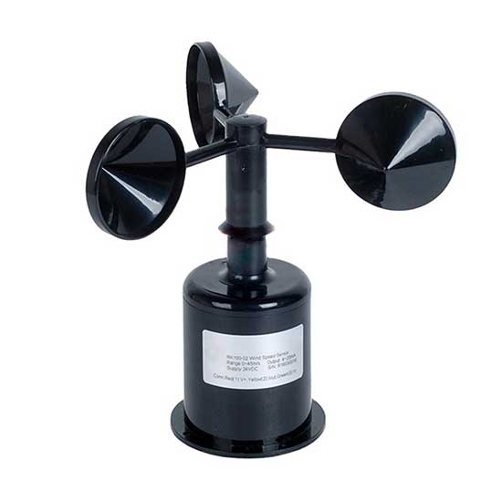
Unlike the analog output version anemometer, this anemometer output pulse reflects the wind speed more accurately. Besides, this anemometer is totally waterproof, with a stable installation design, and suitable for outdoor applications.
Features & Specifications
It operates between 5 volts to 30 volts of DC. The output is pulse type with a resolution of 0.0875 meters per second. The wind measuring ranges from 0 to 70 meters per second.
Wiring & Pinout
The anemometer sensor has four wires; the brown is the VCC pin which can accept 5 volts to 30-volt input. The Black is the GND pin, the Blue is the NPNR output pin, and the Green is the PNP output pin. We won’t use the green wire in this project.
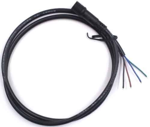
| Wires | Mark | Definition |
| Brown line | VCC | Power supply |
| Black line | GND | Grounding |
| Green line | (PNP)OUTPUT | Pulse output |
| Blue line | (NPNR)OUTPUT | Pulse output |
Interfacing NPN Pulse Output Anemometer with ESP8266
Alright, let’s move to the Practical part. This is an ESP8266 NodeMCU board. We will use this microcontroller in this project to read wind speed and upload data to Arduino IoT Cloud. In order to display the wind speed, we will use an I2C OLED display. I2C will help in reducing the number of wires.
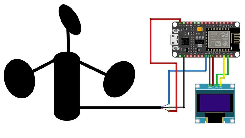
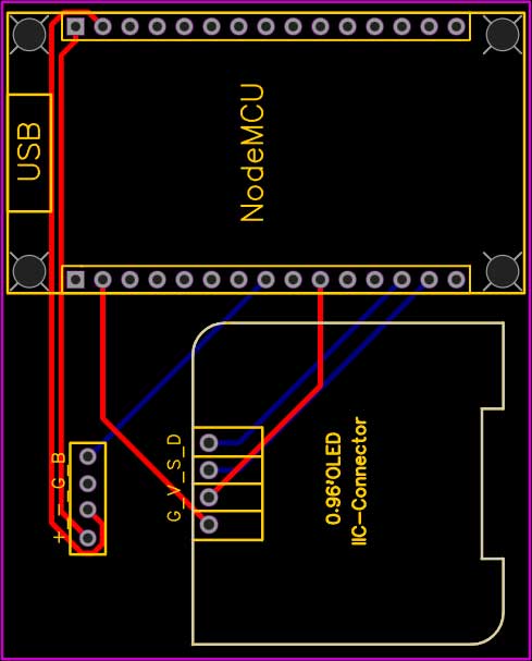
This is the circuit diagram for this project. The anemometer sensor is powered through a Vin pin of NodeMCU. The output pin of the anemometer is connected to the D5 pin of NodeMCU. Similarly, the OLED is connected to the I2C pins of ESP8266 NodeMCU and Powered with a 3.3 Volt pin. I used a breadboard to assemble the circuit.
The ESP8266 NodeMCU board, OLED display unit, and the anemometer sensor all of them are connected to each other as per the circuit diagram. I powered the ESP8266 board using the USB power from the power bank. You may use any 5V DC adapter.
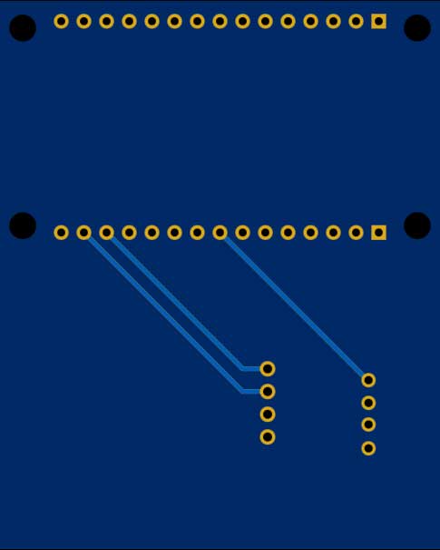
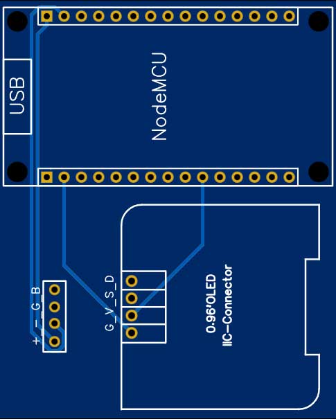
Ordering Custom PCB Online
Do you want professional PCBs like this one that looks so good then use the services of PCBWay.com
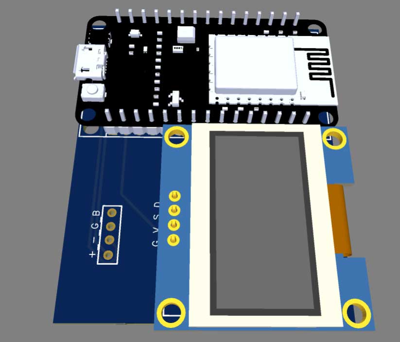
Because PCBWay is a one-stop solution for all your PCB needs like PCB prototyping, SMD stencils, PCB assembly, 3D printing, etc.

So, get your first prototype PCB ready from pcbway.com, the Gerber file link is provided below.
- Just click on the PCB Instant quote tab.
- Then click on Quick Order PCB.
- Now Upload your Gerber file
- Select your preferred shipping method
- Place your order.
Setting Up Arduino IoT Cloud
Now it’s time to set up the Arduino IoT Cloud Dashboard. So, go to the Arduino Store. Click on IoT Cloud.

Then you need to create a Thing first.

Click on create Thing and Give it a name anything like “IoT Anemometer“
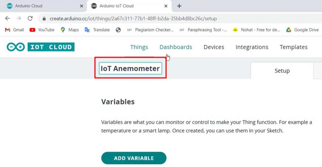
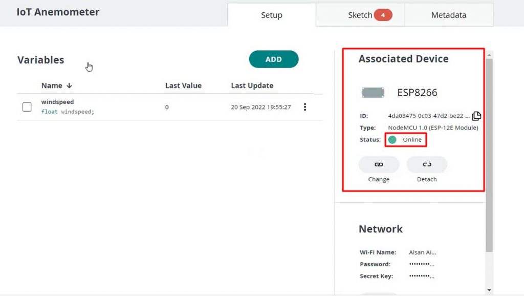
Now we need to create a variable. For that, click on add variable.
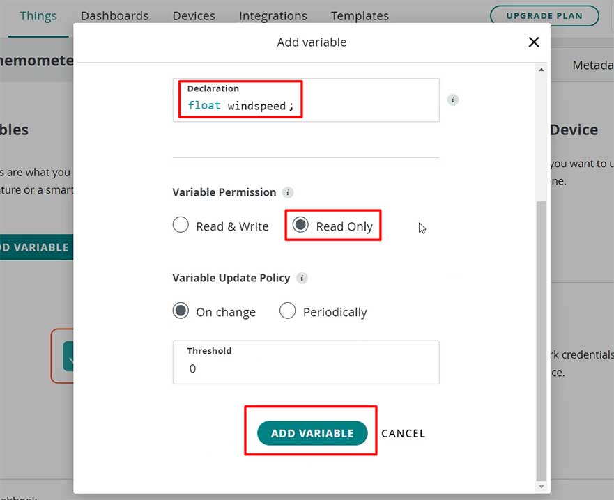
Name the variable “windspeed”. In the variable type, select the floating point number. So an automatic declaration of variables will be done. Now set the variable permission to Read-only. Then click on the Add variable button to create the variable.
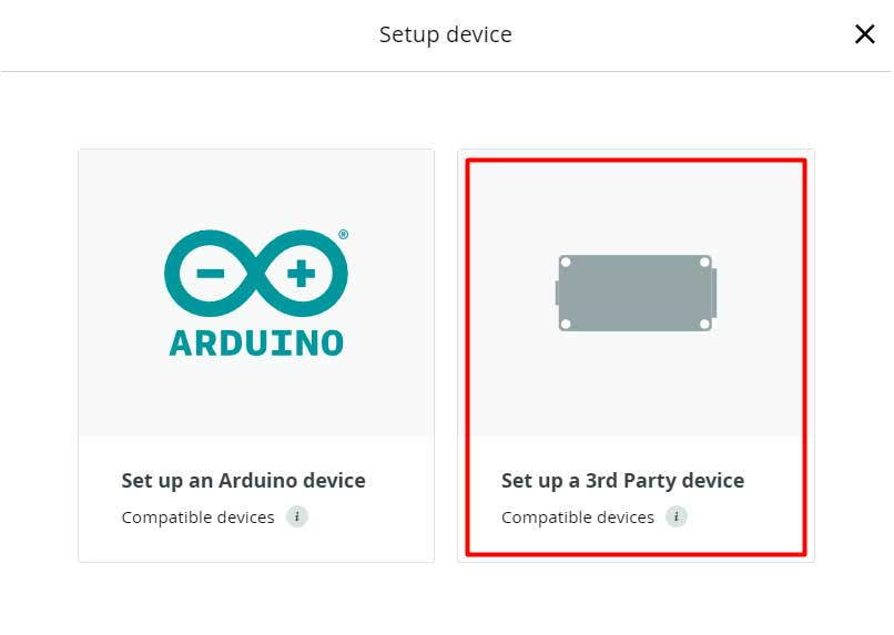
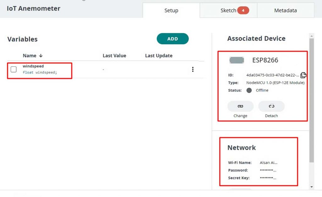
Now, we need to configure a device as well. For that, select the device option. From the list, select a 3rd party device.
Then select ESP8266. From this list, select NodeMCU 1.0 ESP-12E Module.
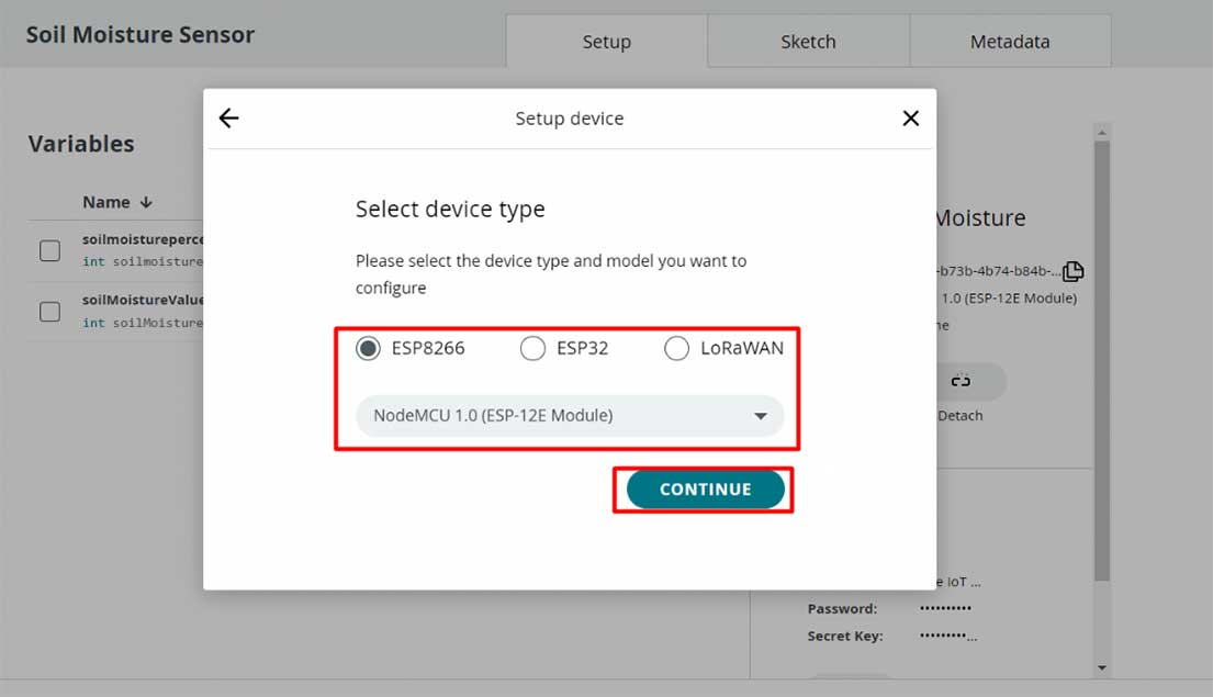
Click to continue and give any name to the device. Give it a name like “IoT Anemometer” Then click next.
So device ID & Secret Key is created here. Save this device ID for the coding part. Or simply download this PDF File which has the information about the Secret Key. Then click on continue.

Now again, you need to set up the Network Credentials. So input your SSID, Password, and Secret Key that you created earlier.
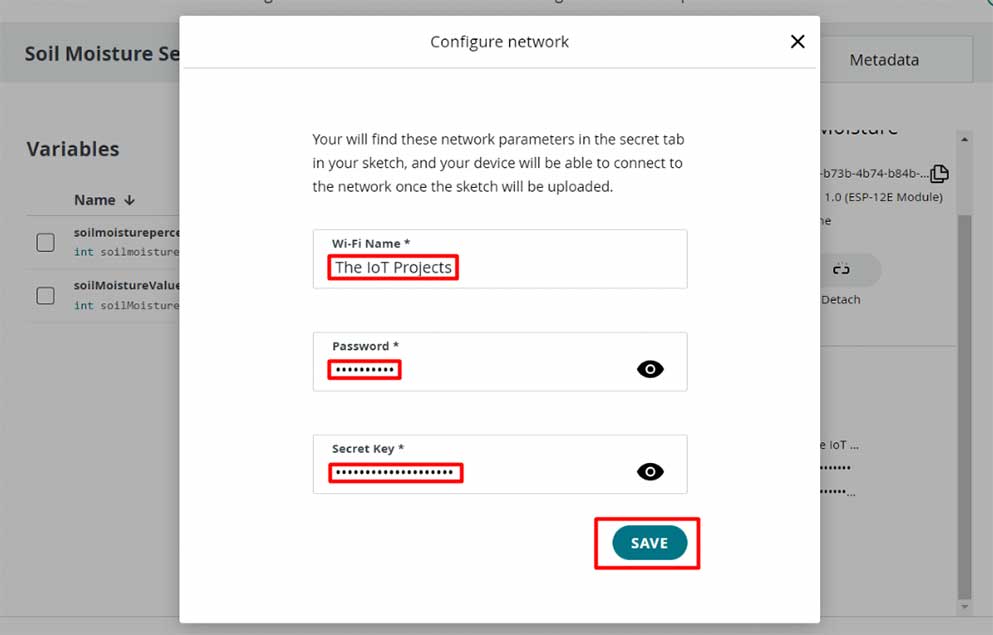
Finally, everything is set now.
Design Web and Mobile Dashboards
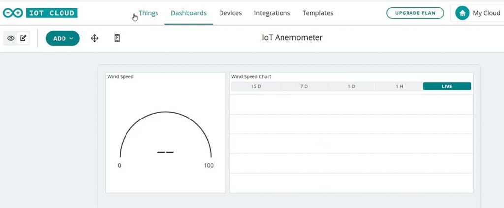
Go to the dashboard. Here we need to build a Web dashboard and Mobile app dashboard for monitoring wind speed from anywhere in the world.
You can also provide a name to the dashboard. I am giving “IoT Anemometer” as a dashboard name.
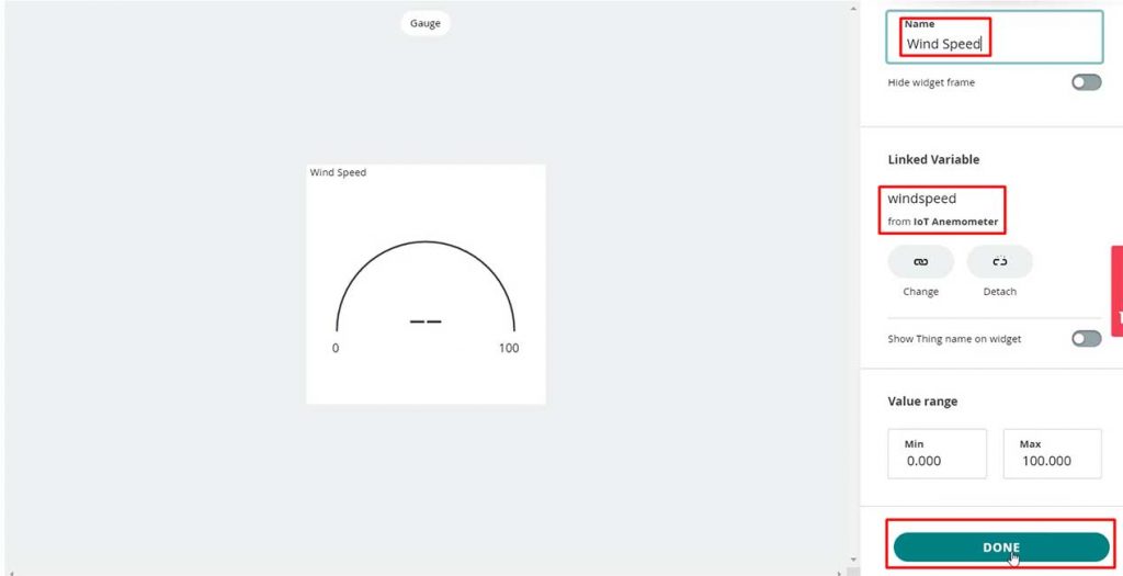
Now click on the add button then select the Gauge widget. Provide a name to the widget. I am giving “Wind Speed”. Also, link the same variable then click on done.
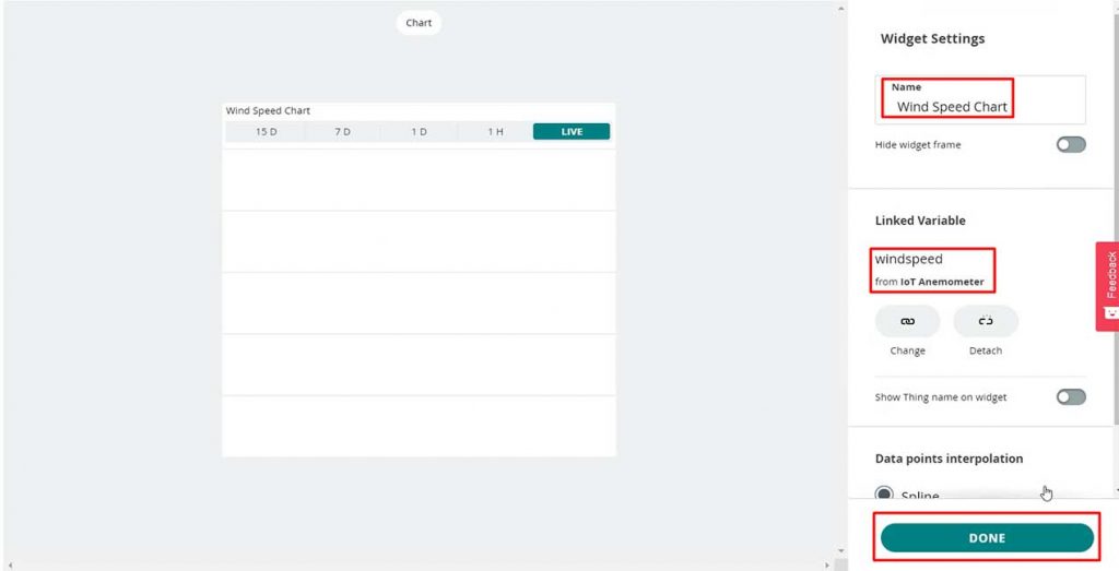
Similarly, add a chart widget and link the “windspeed” variable. You can arrange and resize the widget as per your requirements for a web dashboard as well as a mobile dashboard as shown here.
So finally, we are done with the IoT dashboard setup.
Source Code/Program
Now go to the Things Tab and click on “IoT Anemometer” Then click on the sketch Tab. Copy the program code from below.
/*
  Sketch generated by the Arduino IoT Cloud Thing "Untitled"
  https://create.arduino.cc/cloud/things/d812feb6-132b-49de-95f4-ea2ff3292c1e

  Arduino IoT Cloud Variables description

  The following variables are automatically generated and updated when changes are made to the Thing

  float windspeed;

  Variables which are marked as READ/WRITE in the Cloud Thing will also have functions
  which are called when their values are changed from the Dashboard.
  These functions are generated with the Thing and added at the end of this sketch.
*/

#include "thingProperties.h"

#include <Adafruit_GFX.h>
#include <Adafruit_SSD1306.h>


#define SCREEN_WIDTH 128 // OLED display width, in pixels
#define SCREEN_HEIGHT 64 // OLED display height, in pixels
// Declaration for an SSD1306 display connected to I2C (SDA, SCL pins)
#define OLED_RESET     -1 // Reset pin # (or -1 if sharing Arduino reset pin)
Adafruit_SSD1306 display(SCREEN_WIDTH, SCREEN_HEIGHT, &Wire, OLED_RESET);

unsigned long lastDebounceTime = 0;  // the last time the output pin was toggled
unsigned long debounceDelay = 1000;    // the debounce time; increase if the output flickers

int pinInterrupt = 14; //D5

int Count = 0;

void onChange()
{
  if ( digitalRead(pinInterrupt) == LOW )
    Count++;
}


void setup() {
  // Initialize serial and wait for port to open:
  Serial.begin(115200);
  // This delay gives the chance to wait for a Serial Monitor without blocking if none is found
  delay(1500);

  // Defined in thingProperties.h
  initProperties();

  // Connect to Arduino IoT Cloud
  ArduinoCloud.begin(ArduinoIoTPreferredConnection);

  /*
     The following function allows you to obtain more information
     related to the state of network and IoT Cloud connection and errors
     the higher number the more granular information you’ll get.
     The default is 0 (only errors).
     Maximum is 4
  */
  setDebugMessageLevel(2);
  ArduinoCloud.printDebugInfo();

  pinMode( pinInterrupt, INPUT_PULLUP);// set the interrupt pin

  //Enable
  attachInterrupt( digitalPinToInterrupt(pinInterrupt), onChange, FALLING);

  display.begin(SSD1306_SWITCHCAPVCC, 0x3C);
  delay(500);
  display.clearDisplay();
  display.setTextColor(WHITE);
}

void loop() {
  ArduinoCloud.update();
  // Your code here

  if ((millis() - lastDebounceTime) > debounceDelay)
  {
    lastDebounceTime = millis();
    windspeed = ((Count * 8.75) / 100);

    Serial.print(windspeed);
    Serial.println("m/s");

    //clear display
    display.clearDisplay();

    display.setTextSize(2);
    display.setCursor(4, 0);
    display.print("Anemometer");

    display.setCursor(2, 20); //oled display
    display.setTextSize(2);
    display.println("Wind Speed");

    display.setCursor(0, 40); //oled display
    display.setTextSize(3);
    display.print(windspeed);
    display.setCursor(70, 45);
    display.setTextSize(2);
    display.println(" m/s");
    display.display();

    Count = 0;

  }
  delay(1);


}
The code is very simple! I have already explained this program code in my previous project visit this link to know how this code works.
Uploading Source Code
Apart from the code part, we need to upload the code. But before that, we need to install an Agent to flash the code directly from the browser. Follow the instructions on your screen to install the agent. Once the driver is installed, the COM port will appear.
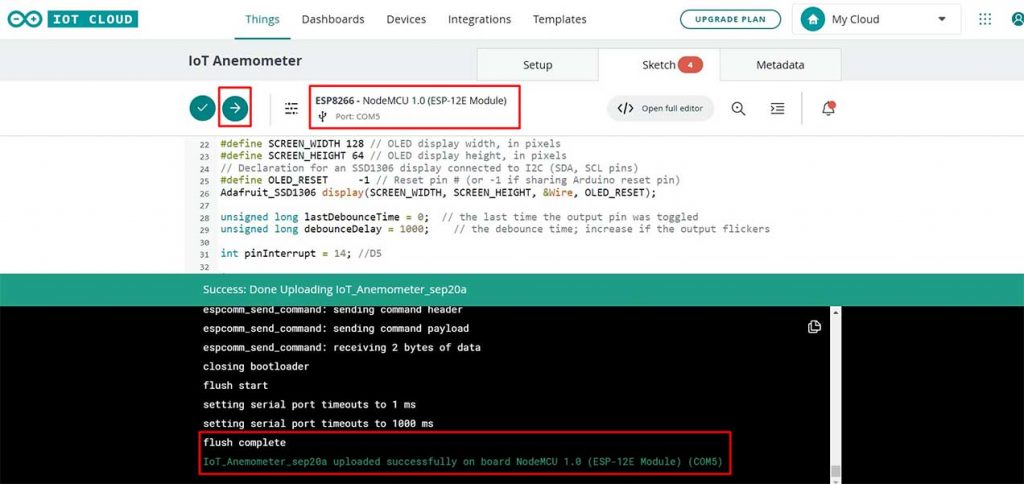
Then select the ESP8266 NodeMCU Board from the list and the COM port as well. Then, upload the code. It will take some time to upload the code and when it’s done, some upload success message will appear.
Measuring Wind Speed & Testing Arduino IoT Cloud
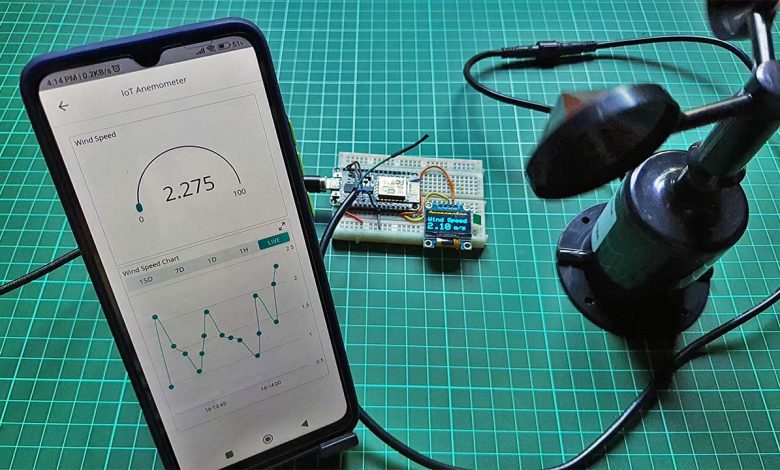
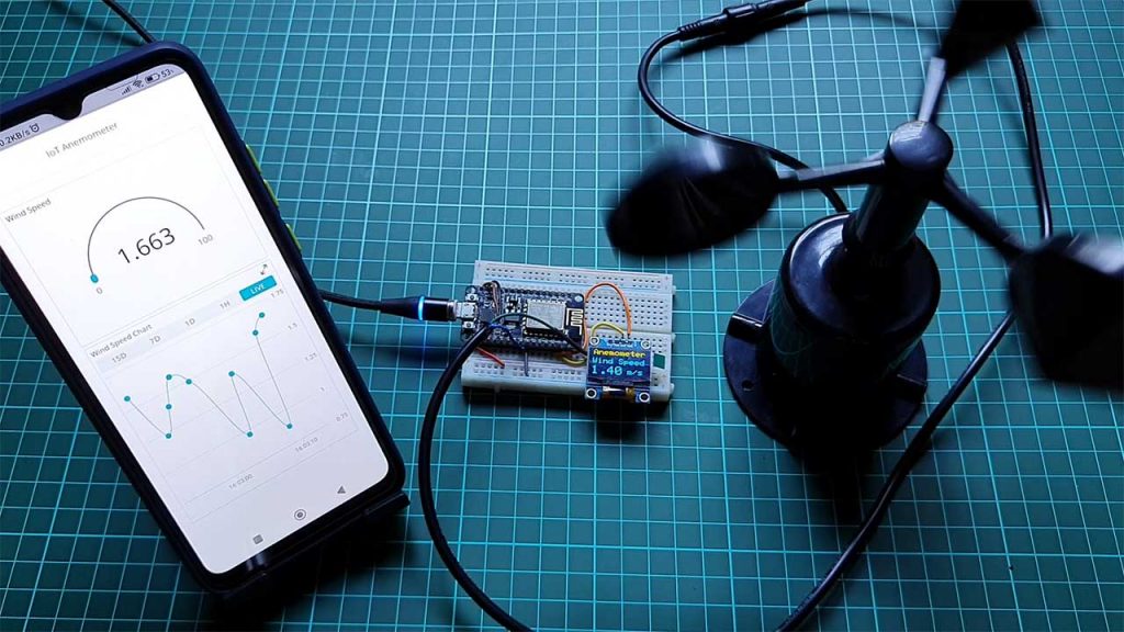
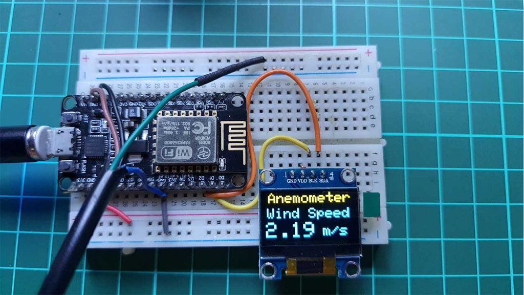
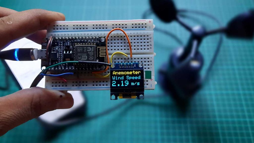
After uploading the code and powering up the entire device, the OLED will display a wind speed In m/s. The wind speed will change as the cup of the anemometer starts moving. I am currently testing indoors therefore I’m rotating it using my hand. As the cop spins faster the more is the wind speed.
I am measuring the speed as a meter per second but you can change the unit to miles per hour.
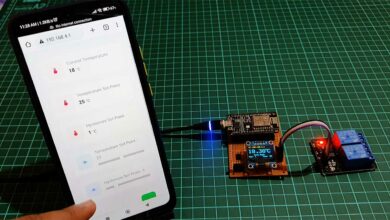
Similarly, You can also monitor the wind speed data on the Arduino IoT Cloud dashboard. You can also download the “Arduino IoT remote” App and sign in with the same credentials to monitor data through your smartphone.
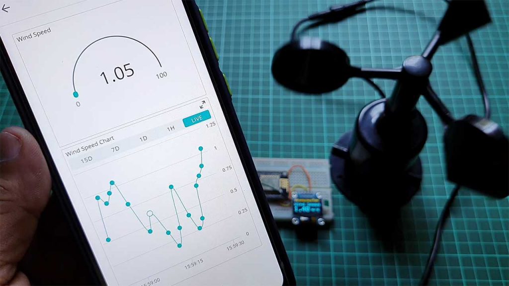
Now, I placed the entire unit on the roof of my house, and currently, the Cups are moving. The wind speed shown here is between 0 to 4 meters per second. You can fix this anemometer during windy days.
Conclusion
Alright, that’s all for IoT based Anemometer using ESP8266 & Arduino IoT Cloud project. The complete project details including device information purchase link source code and written guide are provided for you. In case you have any other questions you can comment in the comment section below. Thank you so much for Visiting.