RFID Based Door Lock Control System using Raspberry Pi Pico
Raspberry Pi Pico based RFID Door Lock Control System
Overview: RFID Door Lock using Raspberry Pi Pico
In this tutorial, we will be discussing the implementation of an RFID based door lock control system using Raspberry Pi Pico and MicroPython.
Technological advancement has revolutionized how we secure our homes and offices. The RFID based door lock control system using Raspberry Pi Pico and MFRC-522 module is a modern and secure method to control access to your property. With this system, you can control access to your doors using a simple RFID card, which acts as a key. Today, we will walk through the process of building an RFID based door lock control system. Basically, we will also explain the code used to run this system, and how to customize it to your needs.
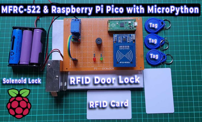
In this project, we will learn to read RFID tag UID from the RFID MFRC-522 Module by scanning RFID Cards. Later we will use the RFID UID numbers in the MicroPython Code to make an RFID Access Control System. If a registered and correct RFID tag number is found, the Solenoid lock will open and the green LED indicator will let you know. In case, if the wrong RFID is scanned, the Red LED indicator followed by a buzzer sound lets you know that the Card is not registered to a system. So, access to the door lock is not available.
- Getting Started with Raspberry Pi Pico using MicroPython
- Read Internal Temperature Sensor Value from Raspberry Pi Pico
- Interface BME280 with Raspberry Pi Pico using MicroPython
- IoT Smart RFID Door Lock System Using NodeMCU ESP8266
Components Required
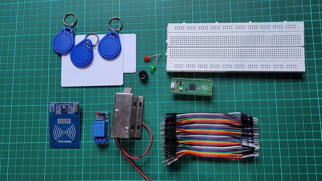
The system will consist of an RFID reader, an electronic lock attached to the 5V relay, a buzzer to provide audio feedback, LEDs as indicators, and a Raspberry Pi Pico microcontroller board. You will also need a few jumper cables and a breadboard for assembly. But, I recommend you use a custom PCB for this project. Actually, you can easily purchase the required components from below.
| S.N | COMPONENTS NAME | QUANTITY | PURCHASE LINKS |
|---|---|---|---|
| 1 | Raspberry Pi Pico Board | 1 | Amazon | AliExpress |
| 2 | RFID Module RC522 | 1 | Amazon | AliExpress |
| 3 | RFID Cards | 5 | Amazon | AliExpress |
| 4 | 12V Solenoid Lock | 1 | Amazon | AliExpress |
| 5 | 5V Buzzer | 1 | Amazon | AliExpress |
| 6 | 5V Single Channel Relay | 1 | Amazon | AliExpress |
| 7 | 5MM Mixed LEDs | 10 | Amazon | AliExpress |
| 8 | Breadboard | 1 | Amazon | AliExpress |
| 9 | 12V Power Supply | 1 | Amazon | AliExpress |
| 10 | Jumper Cables | 20 | Amazon | AliExpress |
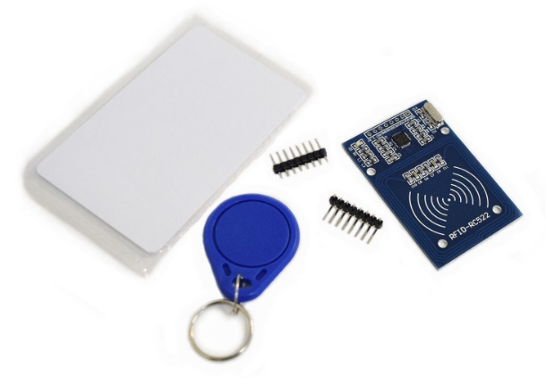
RC522 RFID Module
The NXP Semiconductor MFRC-522 IC serves as the base for the RC522 RFID module. Both a key tag and an RFID card tag are usually included in the module. It is used to write a tag and has 1KB of memory. This memory can be used to store any message.
A 13.56MHz electromagnetic field is produced by the RC522 RFID reader module in order to communicate with RFID tags. Through a 4-pin SPI connector, the reader may communicate with any microcontroller. It can communicate with a maximum data rate of 10 Mbps in SPI Mode. Additionally, it supports the I2C and UART protocols for communication.
The RC522 RFID module can be configured to create an interrupt, which enables it to notify us when a tag approaches. The module can operate between 2.5 and 3.3 volts, however, its SPI pin can withstand 5 volts. As a result, the RC522 Module can be connected to an Arduino or Raspberry Pi Pico.
Specifications
- The maximum data transfer speed is 10 Mbit/s for SPI.
- Voltage Range: 2.5-3.3 V
- 13.56 MHz is the operating frequency.
- DC current range: 13–26 mA 3.3 V
- 10-13 mA/DC 3.3 V is the idle current.
- 80 uA sleep current
- Maximum current: 30 mA
- Range of Read: 0 to 35 mm (mifare1 card)
- Mifare1 S50, Mifare1 S70, MIFARE Ultralight, MIFARE Pro, and MIFARE DESFire RFID RC522 Pinout have supported card types.
- The SPI, I2C, and UART communication modes are used by the RFID RC522. It has a total number of 9 pins.
RFID MFRC522 Pinout
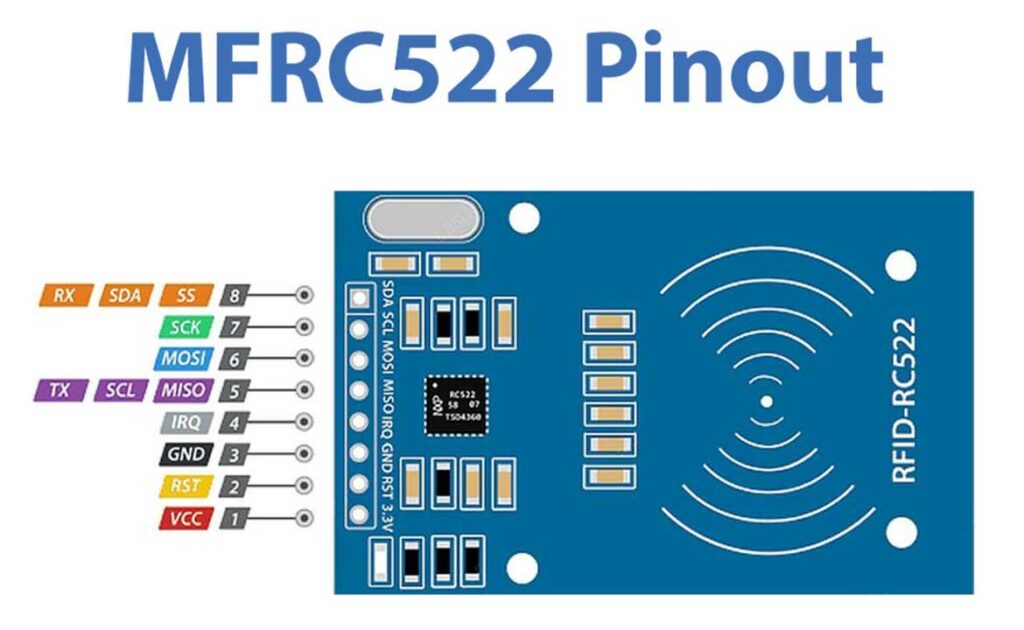
- SDA SCL: I2C Communication pins. DATA and CLOCK.
- SS SCK MOSI MISO: SPI communication pins. Slave Select, Clock, MOSI, and MISO.
- RX TX: UART Communication pins.
- IRQ: Interrupt signal from the module to indicate RFID tag detection.
- GND: Ground pin that needs to be connected to the GND pin on the Arduino.
- RST: Reset pin for the module.
- VCC: Supply pin for the module (2.5V to 3.3V).
Interfacing RC522 RFID Reader Module with Raspberry Pi Pico
The circuit connection for this project is relatively simple. The MFRC522 RFID reader is connected to the Raspberry Pi Pico using the SPI interface. The 5V DC relay is used to control the door lock, and the LED is used to indicate whether the lock is open or closed. The buzzer provides audio feedback when an unauthorized RFID card is detected.
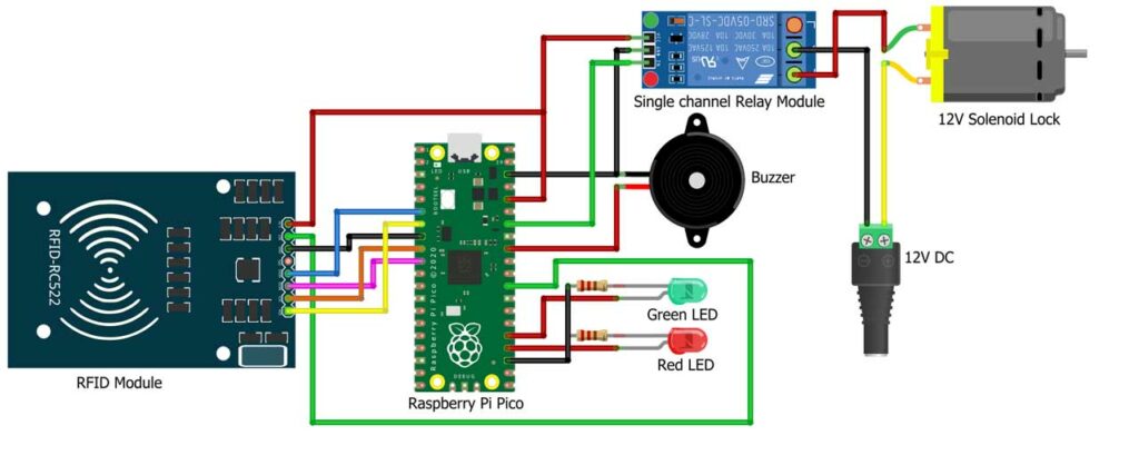
The connections are as follows:
- Connect the MFRC522 SDA pin to the Raspberry Pi Pico GPIO pin 5.
- Connect the MFRC522 SCK pin to the Raspberry Pi Pico GPIO pin 6.
- Connect the MFRC522 MISO pin to the Raspberry Pi Pico GPIO pin 4.
- Connect the MFRC522 MOSI pin to the Raspberry Pi Pico GPIO pin 7.
- Connect the MFRC522 RST pin to the Raspberry Pi Pico GPIO pin 22.
- Connect the 5V DC relay IN1 pin to the Raspberry Pi Pico GPIO pin 28.
- Connect the LED anode to the Raspberry Pi Pico GPIO pin 19 (for green LED) and GPIO pin 18 (for red LED).
- Connect the LED cathode to a 220Ω resistor, and connect the other end of the resistor to the GND pin on the Raspberry Pi Pico.
- Connect the buzzer positive terminal to the Raspberry Pi Pico GPIO pin 27.
- Connect the buzzer negative terminal to the GND pin on the Raspberry Pi Pico.
- Connect the DC 12V electric lock to the 5V DC relay.
- Connect all VCC to 3.3V pin and GND to GND pin of Raspberry Pi Pico
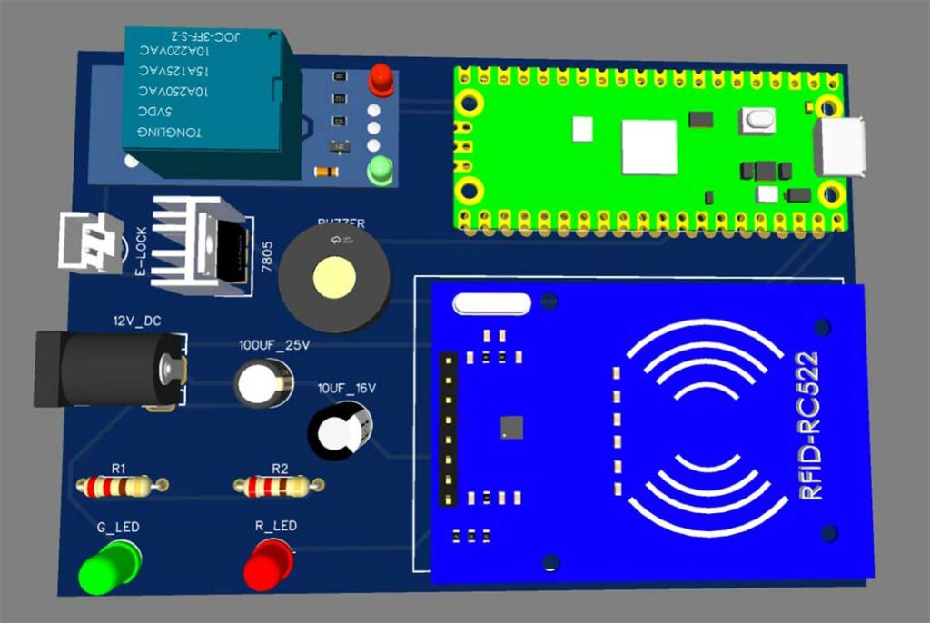
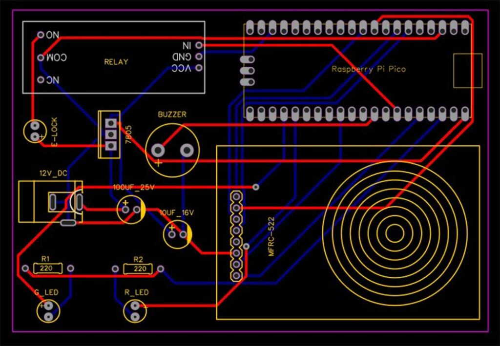
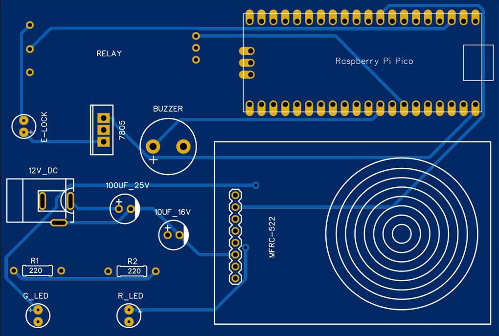
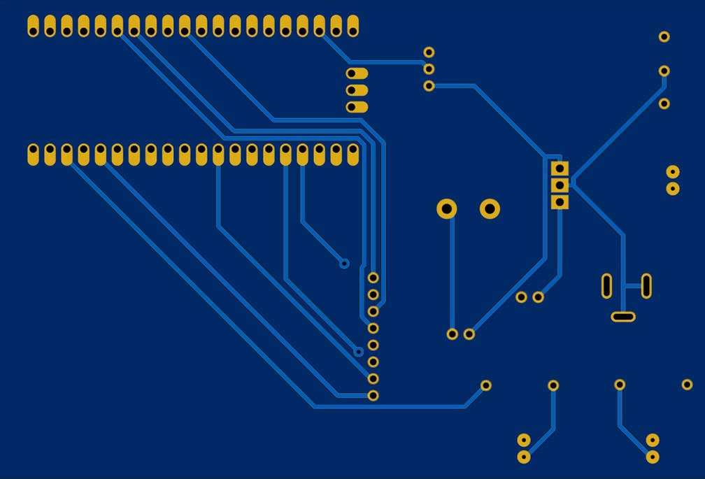
Project PCB Gerber File & PCB Ordering Online
To implement this whole system you will need a PCB. You can use breadboard assembly just to test this project. So, to make your work easier I have designed a custom PCB for this project. You can directly order your PCB from PCBWay.com.
Now you can visit the PCBWay official website by clicking here: PCBWay.com. So you will be directed to the PCBWay website.

You can now upload the Gerber File to the Website and place an order. The PCB quality is superb & high standard. That is why most people trust PCBWay for PCB & PCBA Services. PCBWay is a leading manufacturer of high-quality PCBs and offers a wide range of services, including PCB fabrication, assembly, and components sourcing.
MicroPython Code
We will be programming the Raspberry Pi Pico with MicroPython Code to communicate with RFID RC522 Module.
The code is divided into 2 parts:
- mfrc522.py which is the library for RC522 Module.
- main.py which is the code to read the RFID Tags and Control Door Lock.
Connect Raspberry Pi Pico to your laptop using a micro USB cable.
mfrc522.py
Copy the code provided for “mfrc522.py“.
from machine import Pin, SPI
from os import uname


class MFRC522:

    DEBUG = False
    OK = 0
    NOTAGERR = 1
    ERR = 2

    REQIDL = 0x26
    REQALL = 0x52
    AUTHENT1A = 0x60
    AUTHENT1B = 0x61

    PICC_ANTICOLL1 = 0x93
    PICC_ANTICOLL2 = 0x95
    PICC_ANTICOLL3 = 0x97


    def __init__(self, sck, mosi, miso, rst, cs,baudrate=1000000,spi_id=0):

        self.sck = Pin(sck, Pin.OUT)
        self.mosi = Pin(mosi, Pin.OUT)
        self.miso = Pin(miso)
        self.rst = Pin(rst, Pin.OUT)
        self.cs = Pin(cs, Pin.OUT)

        self.rst.value(0)
        self.cs.value(1)

        board = uname()[0]

        if board == 'WiPy' or board == 'LoPy' or board == 'FiPy':
            self.spi = SPI(0)
            self.spi.init(SPI.MASTER, baudrate=1000000, pins=(self.sck, self.mosi, self.miso))
        elif (board == 'esp8266') or (board == 'esp32'):
            self.spi = SPI(baudrate=100000, polarity=0, phase=0, sck=self.sck, mosi=self.mosi, miso=self.miso)
            self.spi.init()
        elif board == 'rp2':
            self.spi = SPI(spi_id,baudrate=baudrate,sck=self.sck, mosi= self.mosi, miso= self.miso)
        else:
            raise RuntimeError("Unsupported platform")

        self.rst.value(1)
        self.init()

    def _wreg(self, reg, val):

        self.cs.value(0)
        self.spi.write(b'%c' % int(0xff & ((reg << 1) & 0x7e)))
        self.spi.write(b'%c' % int(0xff & val))
        self.cs.value(1)

    def _rreg(self, reg):

        self.cs.value(0)
        self.spi.write(b'%c' % int(0xff & (((reg << 1) & 0x7e) | 0x80)))
        val = self.spi.read(1)
        self.cs.value(1)

        return val[0]

    def _sflags(self, reg, mask):
        self._wreg(reg, self._rreg(reg) | mask)

    def _cflags(self, reg, mask):
        self._wreg(reg, self._rreg(reg) & (~mask))

    def _tocard(self, cmd, send):

        recv = []
        bits = irq_en = wait_irq = n = 0
        stat = self.ERR

        if cmd == 0x0E:
            irq_en = 0x12
            wait_irq = 0x10
        elif cmd == 0x0C:
            irq_en = 0x77
            wait_irq = 0x30

        self._wreg(0x02, irq_en | 0x80)
        self._cflags(0x04, 0x80)
        self._sflags(0x0A, 0x80)
        self._wreg(0x01, 0x00)

        for c in send:
            self._wreg(0x09, c)
        self._wreg(0x01, cmd)

        if cmd == 0x0C:
            self._sflags(0x0D, 0x80)

        i = 2000
        while True:
            n = self._rreg(0x04)
            i -= 1
            if ~((i != 0) and ~(n & 0x01) and ~(n & wait_irq)):
                break

        self._cflags(0x0D, 0x80)

        if i:
            if (self._rreg(0x06) & 0x1B) == 0x00:
                stat = self.OK

                if n & irq_en & 0x01:
                    stat = self.NOTAGERR
                elif cmd == 0x0C:
                    n = self._rreg(0x0A)
                    lbits = self._rreg(0x0C) & 0x07
                    if lbits != 0:
                        bits = (n - 1) * 8 + lbits
                    else:
                        bits = n * 8

                    if n == 0:
                        n = 1
                    elif n > 16:
                        n = 16

                    for _ in range(n):
                        recv.append(self._rreg(0x09))
            else:
                stat = self.ERR

        return stat, recv, bits

    def _crc(self, data):

        self._cflags(0x05, 0x04)
        self._sflags(0x0A, 0x80)

        for c in data:
            self._wreg(0x09, c)

        self._wreg(0x01, 0x03)

        i = 0xFF
        while True:
            n = self._rreg(0x05)
            i -= 1
            if not ((i != 0) and not (n & 0x04)):
                break

        return [self._rreg(0x22), self._rreg(0x21)]

    def init(self):

        self.reset()
        self._wreg(0x2A, 0x8D)
        self._wreg(0x2B, 0x3E)
        self._wreg(0x2D, 30)
        self._wreg(0x2C, 0)
        self._wreg(0x15, 0x40)
        self._wreg(0x11, 0x3D)
        self.antenna_on()

    def reset(self):
        self._wreg(0x01, 0x0F)

    def antenna_on(self, on=True):

        if on and ~(self._rreg(0x14) & 0x03):
            self._sflags(0x14, 0x03)
        else:
            self._cflags(0x14, 0x03)

    def request(self, mode):

        self._wreg(0x0D, 0x07)
        (stat, recv, bits) = self._tocard(0x0C, [mode])

        if (stat != self.OK) | (bits != 0x10):
            stat = self.ERR

        return stat, bits

    def anticoll(self,anticolN):

        ser_chk = 0
        ser = [anticolN, 0x20]

        self._wreg(0x0D, 0x00)
        (stat, recv, bits) = self._tocard(0x0C, ser)

        if stat == self.OK:
            if len(recv) == 5:
                for i in range(4):
                    ser_chk = ser_chk ^ recv[i]
                if ser_chk != recv[4]:
                    stat = self.ERR
            else:
                stat = self.ERR

        return stat, recv


    def PcdSelect(self, serNum,anticolN):
        backData = []
        buf = []
        buf.append(anticolN)
        buf.append(0x70)
        #i = 0
        ###xorsum=0;
        for i in serNum:
            buf.append(i)
        #while i<5:
        #    buf.append(serNum[i])
        #    i = i + 1
        pOut = self._crc(buf)
        buf.append(pOut[0])
        buf.append(pOut[1])
        (status, backData, backLen) = self._tocard( 0x0C, buf)
        if (status == self.OK) and (backLen == 0x18):
            return  1
        else:
            return 0


    def SelectTag(self, uid):
        byte5 = 0

        #(status,puid)= self.anticoll(self.PICC_ANTICOLL1)
        #print("uid",uid,"puid",puid)
        for i in uid:
            byte5 = byte5 ^ i
        puid = uid + [byte5]

        if self.PcdSelect(puid,self.PICC_ANTICOLL1) == 0:
            return (self.ERR,[])
        return (self.OK , uid)

    def tohexstring(self,v):
        s="["
        for i in v:
            if i != v[0]:
                s = s+ ", "
            s=s+ "0x{:02X}".format(i)
        s= s+ "]"
        return s


    def SelectTagSN(self):
        valid_uid=[]
        (status,uid)= self.anticoll(self.PICC_ANTICOLL1)
        #print("Select Tag 1:",self.tohexstring(uid))
        if status != self.OK:
            return  (self.ERR,[])

        if self.DEBUG:   print("anticol(1) {}".format(uid))
        if self.PcdSelect(uid,self.PICC_ANTICOLL1) == 0:
            return (self.ERR,[])
        if self.DEBUG:   print("pcdSelect(1) {}".format(uid))

        #check if first byte is 0x88
        if uid[0] == 0x88 :
            #ok we have another type of card
            valid_uid.extend(uid[1:4])
            (status,uid)=self.anticoll(self.PICC_ANTICOLL2)
            #print("Select Tag 2:",self.tohexstring(uid))
            if status != self.OK:
                return (self.ERR,[])
            if self.DEBUG: print("Anticol(2) {}".format(uid))
            rtn =  self.PcdSelect(uid,self.PICC_ANTICOLL2)
            if self.DEBUG: print("pcdSelect(2) return={} uid={}".format(rtn,uid))
            if rtn == 0:
                return (self.ERR,[])
            if self.DEBUG: print("PcdSelect2() {}".format(uid))
            #now check again if uid[0] is 0x88
            if uid[0] == 0x88 :
                valid_uid.extend(uid[1:4])
                (status , uid) = self.anticoll(self.PICC_ANTICOLL3)
                #print("Select Tag 3:",self.tohexstring(uid))
                if status != self.OK:
                    return (self.ERR,[])
                if self.DEBUG: print("Anticol(3) {}".format(uid))
                if self.MFRC522_PcdSelect(uid,self.PICC_ANTICOLL3) == 0:
                    return (self.ERR,[])
                if self.DEBUG: print("PcdSelect(3) {}".format(uid))
        valid_uid.extend(uid[0:5])
        # if we are here than the uid is ok
        # let's remove the last BYTE whic is the XOR sum

        return (self.OK , valid_uid[:len(valid_uid)-1])
        #return (self.OK , valid_uid)


    def auth(self, mode, addr, sect, ser):
        return self._tocard(0x0E, [mode, addr] + sect + ser[:4])[0]

    def authKeys(self,uid,addr,keyA=None, keyB=None):
        status = self.ERR
        if keyA is not None:
            status = self.auth(self.AUTHENT1A, addr, keyA, uid)
        elif keyB is not None:
            status = self.auth(self.AUTHENT1B, addr, keyB, uid)
        return status


    def stop_crypto1(self):
        self._cflags(0x08, 0x08)

    def read(self, addr):

        data = [0x30, addr]
        data += self._crc(data)
        (stat, recv, _) = self._tocard(0x0C, data)
        return stat, recv

    def write(self, addr, data):

        buf = [0xA0, addr]
        buf += self._crc(buf)
        (stat, recv, bits) = self._tocard(0x0C, buf)

        if not (stat == self.OK) or not (bits == 4) or not ((recv[0] & 0x0F) == 0x0A):
            stat = self.ERR
        else:
            buf = []
            for i in range(16):
                buf.append(data[i])
            buf += self._crc(buf)
            (stat, recv, bits) = self._tocard(0x0C, buf)
            if not (stat == self.OK) or not (bits == 4) or not ((recv[0] & 0x0F) == 0x0A):
                stat = self.ERR
        return stat


    def writeSectorBlock(self,uid, sector, block, data, keyA=None, keyB = None):
        absoluteBlock =  sector * 4 + (block % 4)
        if absoluteBlock > 63 :
            return self.ERR
        if len(data) != 16:
            return self.ERR
        if self.authKeys(uid,absoluteBlock,keyA,keyB) != self.ERR :
            return self.write(absoluteBlock, data)
        return self.ERR

    def readSectorBlock(self,uid ,sector, block, keyA=None, keyB = None):
        absoluteBlock =  sector * 4 + (block % 4)
        if absoluteBlock > 63 :
            return self.ERR, None
        if self.authKeys(uid,absoluteBlock,keyA,keyB) != self.ERR :
            return self.read(absoluteBlock)
        return self.ERR, None

    def MFRC522_DumpClassic1K(self,uid, Start=0, End=64, keyA=None, keyB=None):
        for absoluteBlock in range(Start,End):
            status = self.authKeys(uid,absoluteBlock,keyA,keyB)
            # Check if authenticated
            print("{:02d} S{:02d} B{:1d}: ".format(absoluteBlock, absoluteBlock//4 , absoluteBlock % 4),end="")
            if status == self.OK:
                status, block = self.read(absoluteBlock)
                if status == self.ERR:
                    break
                else:
                    for value in block:
                        print("{:02X} ".format(value),end="")
                    print("  ",end="")
                    for value in block:
                        if (value > 0x20) and (value < 0x7f):
                            print(chr(value),end="")
                        else:
                            print('.',end="")
                    print("")
            else:
                break
        if status == self.ERR:
            print("Authentication error")
            return self.ERR
        return self.OK
Open the Thonny IDE, create a new file, paste the code, and save it as “mfrc522.py” on your Raspberry Pi Pico.
main.py
Repeat the same steps for the “main.py” code.
from mfrc522 import MFRC522
import utime
from machine import Pin

lock =Pin(28,Pin.OUT)
buzzer = Pin(27, Pin.OUT)
RLed =Pin(18,Pin.OUT)
GLed =Pin(19,Pin.OUT)

lock.value(1)
buzzer.value(0)
RLed.value(0)
GLed.value(0)


def uidToString(uid):
    mystring = ""
    for i in uid:
        mystring = "%02X" % i + mystring
    return mystring

rc522 = MFRC522(spi_id=0,sck=6,miso=4,mosi=7,cs=5,rst=22)

print("")
print("Place the RFID Card")
print("")


while True:

    (stat, tag_type) = rc522.request(rc522.REQALL)

    if stat == rc522.OK:
        (status, raw_uid) = rc522.SelectTagSN()
        if stat == rc522.OK:
            rfid_data = "{:02x}{:02x}{:02x}{:02x}".format(raw_uid[0], raw_uid[1], raw_uid[2], raw_uid[3])
            print("Card detected! UID: {}".format(rfid_data))
            if rfid_data == "81a3dc79":

                lock.value(0)
                GLed.value(1)
                utime.sleep(5)
                lock.value(1)
                GLed.value(0)


            elif rfid_data == "ad6d1583":

                lock.value(0)
                GLed.value(1)
                utime.sleep(5)
                lock.value(1)
                GLed.value(0)

            elif rfid_data == "866080f8":

                lock.value(0)
                GLed.value(1)
                utime.sleep(5)
                lock.value(1)
                GLed.value(0)


            elif rfid_data == "337cd633":

                lock.value(0)
                GLed.value(1)
                utime.sleep(5)
                lock.value(1)
                GLed.value(0)


            else:

                buzzer.value(1)
                RLed.value(1)
                utime.sleep(1)
                buzzer.value(0)
                RLed.value(0)
After you have copied the code, go to the Thonny IDE, click on the new file, and paste this code. This time save this code in Raspberry Pi Pico with the name main.py
Code Explanation
In this code, the mfrc522 library is used to communicate with the RFID reader. The machine library is used to control electronic components such as the door lock, buzzer, and LEDs. Basically, the mfrc522 library provides functions to detect and read data from RFID cards, whereas the machine library provides functions to control digital inputs and outputs.
lock =Pin(28,Pin.OUT)
buzzer = Pin(27, Pin.OUT)
RLed =Pin(18,Pin.OUT)
GLed =Pin(19,Pin.OUT)
The code starts by initializing the pins of the door lock, buzzer, and LEDs as digital outputs.
lock.value(1)
buzzer.value(0)
RLed.value(0)
GLed.value(0)
The lock and buzzer pins are then set to a default state, with the lock locked and the buzzer silent. The red and green LEDs are turned off.
while True:

    (stat, tag_type) = rc522.request(rc522.REQALL)

    if stat == rc522.OK:
        (status, raw_uid) = rc522.SelectTagSN()
        if stat == rc522.OK:
            rfid_data = "{:02x}{:02x}{:02x}{:02x}".format(raw_uid[0], raw_uid[1], raw_uid[2], raw_uid[3])
            print("Card detected! UID: {}".format(rfid_data))
The main loop of the code continuously checks for an RFID card to be detected by the reader using the rc522.request() function. If a card is detected, the code uses rc522.SelectTagSN() function to read the UID of the card and store it in a variable called rfid_data.
            if rfid_data == "81a3dc79":

                lock.value(0)
                GLed.value(1)
                utime.sleep(5)
                lock.value(1)
                GLed.value(0)


            elif rfid_data == "ad6d1583":

                lock.value(0)
                GLed.value(1)
                utime.sleep(5)
                lock.value(1)
                GLed.value(0)

            elif rfid_data == "866080f8":

                lock.value(0)
                GLed.value(1)
                utime.sleep(5)
                lock.value(1)
                GLed.value(0)


            elif rfid_data == "337cd633":

                lock.value(0)
                GLed.value(1)
                utime.sleep(5)
                lock.value(1)
                GLed.value(0)
The UID of the card is then compared with the pre-defined UIDs of the authorized RFID cards. If the UID of the card matches any of the pre-defined UIDs, the door lock is unlocked. At the same time, the green LED is turned on, and the system waits for 5 seconds before relocking the door and turning off the green LED.
            else:

                buzzer.value(1)
                RLed.value(1)
                utime.sleep(1)
                buzzer.value(0)
                RLed.value(0)
If the UID of the card does not match any of the pre-defined UIDs, the buzzer is turned on. Meanwhile, the red LED is turned on, and the system waits for 1 second before turning off the buzzer and red LED. This indicates that the card is not authorized to access the door lock.
Testing: RFID Based Door Lock Control System using Raspberry Pi Pico
Finally, run the code in Thonny IDE. You will be prompted to place your RFID card. Swipe your RFID cards, tags, or key chains to get their UIDs. Use these UIDs in your main.py code to control the door lock.
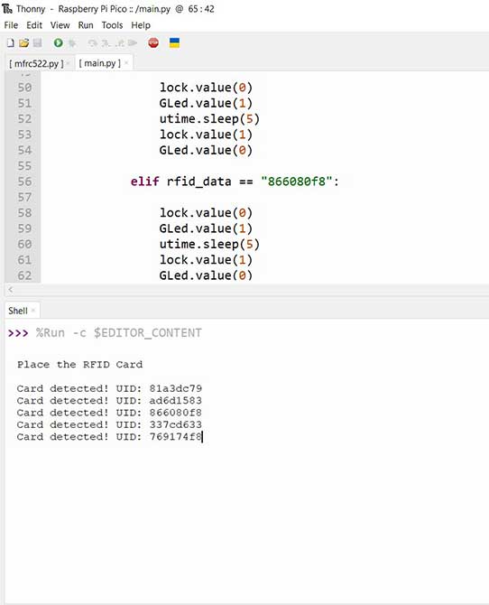
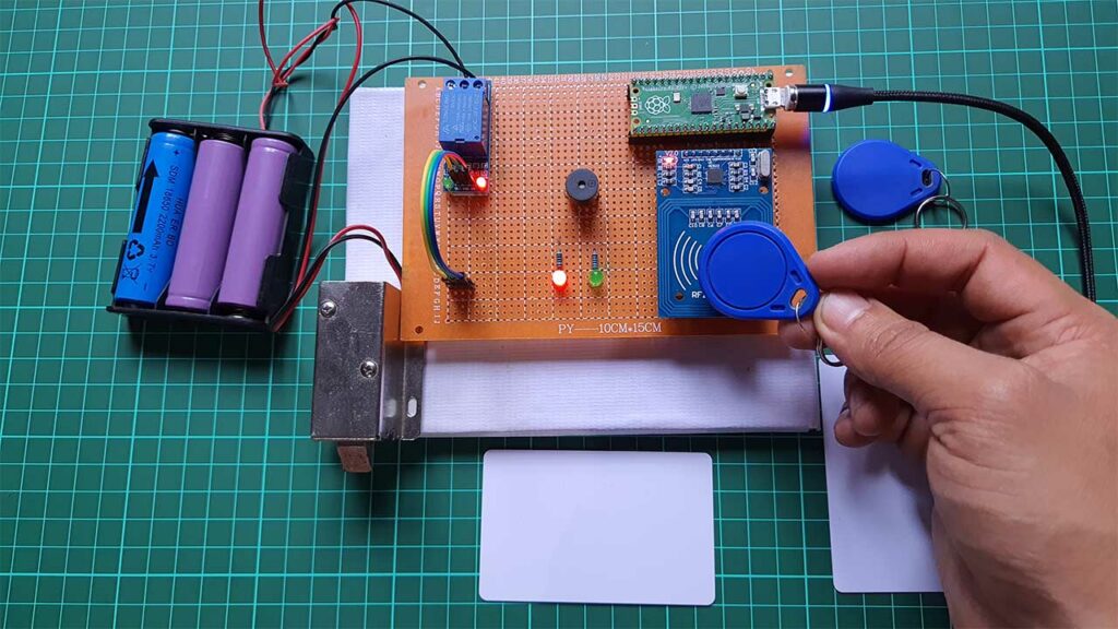
Right now I have two RFID cards and three RFID key chains. One of the key chains is unauthorized. Usually, when the unauthorized RFID card or keychain is used the buzzer is immediately turned ON with RED LED Indicator.
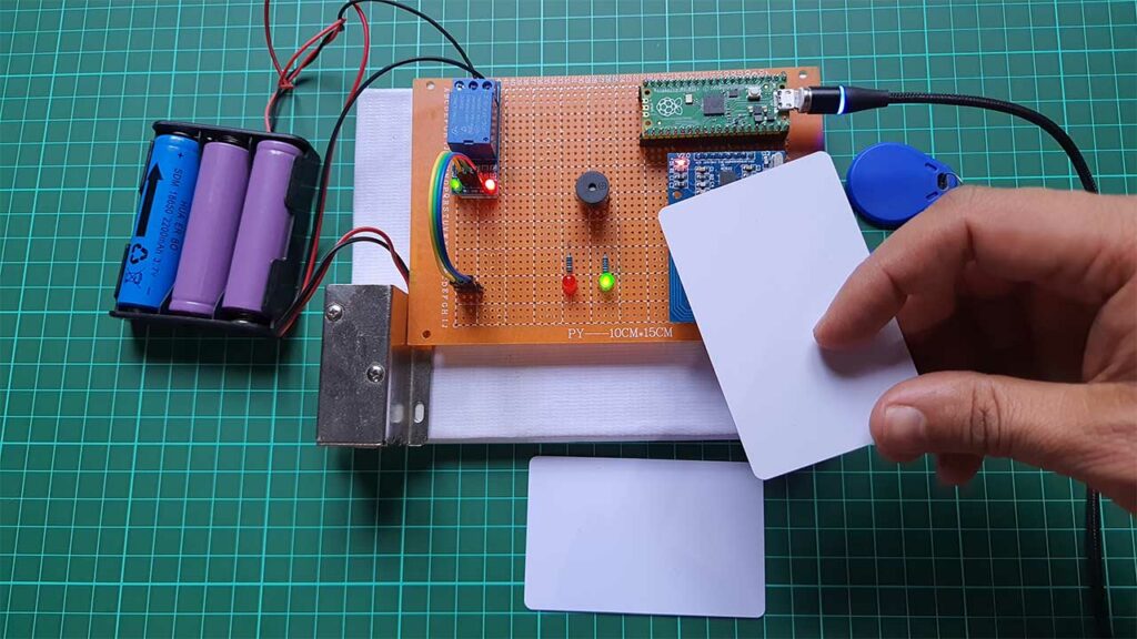
Anyway, when you scan the authorized RFID Card. The electronic door lock is opened. At the same time, the Green LED is turned on indicating successful authentication.
Conclusion
In conclusion, the code provides a simple and efficient solution to control an electronic door lock using RFID technology with a Raspberry Pi Pico and Micropython. The code can be easily modified to add or remove authorized RFID cards and can be integrated with other systems for added functionality. If you have any queries then let me know in the comment section below.

Hi,
Great tutorial! I was wondering if we can use the irq instead of the infinite loop
Thanks!
Mike
I tried this tutorial, but When I connect to the power, the led green already ON.and I can’t tap the NFC tag. thanks
tnx, it’s very useful and good tutorial.
hope you have much brilliant day in your life.