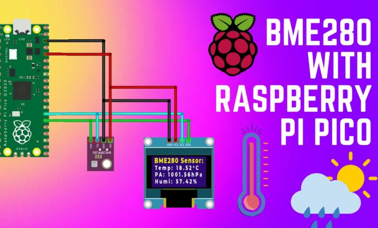
Interface BME280 with Raspberry Pi Pico using MicroPython
BME280 & OLED Display with Pi Pico to measure Temperature Pressure & Humidity
- Overview: BME280 with Raspberry Pi Pico
- Components Required
- Interfacing BME280 Sensor with Raspberry Pi Pico
- MicroPython Code: BME280 & Pi Pico Interfacing
- Interfacing BME280 Sensor with Raspberry Pi Pico & OLED Display
- Project PCB Gerber File & PCB Ordering Online
- MicroPython Code: BME280, OLED Display & Pi Pico Interfacing
- Conclusion
Overview: BME280 with Raspberry Pi Pico
In this tutorial, we will learn how to interface a BME280 sensor with a Raspberry Pi Pico using MicroPython. The BME280 is a popular environmental sensor from BOSCH that can measure temperature, humidity, pressure, and altitude. We will use the BME280 library to develop a MicroPython code in Thonny IDE to read data using the Raspberry Pi Pico.
The tutorial contains circuits, connections, and code to communicate with the BME280 sensor. We will connect the BME280 sensor to the Raspberry Pi Pico via the I2C pins and use a breadboard for assembly and testing. The MicroPython code is divided into two parts: bme280.py and main.py. The main code requires a library for BME280. It contains all the necessary modules and registers details to extract data from the sensor. The first example will display the BME280 sensor reading on the shell and in the second example, we will use a 0.96″ I2C OLED display to display BME280 parameters.
Components Required
The components required for this tutorial include a Raspberry Pi Pico, a BME280 sensor, a 0.96″ OLED display, jumper wires, a breadboard, and a Micro-USB cable. You can easily purchase them from the links provided below.
| S.N | COMPONENTS NAME | QUANTITY | PURCHASE LINKS |
|---|---|---|---|
| 1 | Raspberry Pi Pico Basic Starter Kit | 1 | Amazon | AliExpress |
| 2 | BME280 Sensor | 1 | Amazon | AliExpress |
| 3 | Raspberry Pi Pico | 1 | Amazon | AliExpress |
| 4 | 0.96" I2C OLED Display | 1 | Amazon | AliExpress |
| 5 | Breadboard | 1 | Amazon | AliExpress |
| 6 | Jumper Wires | 10 | Amazon | AliExpress |
BME280 Barometric Pressure Sensor
The BME280 is a Barometric Pressure Sensor that can measure temperature, humidity, and atmospheric pressure.
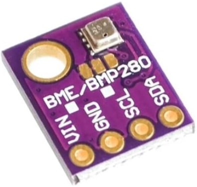
It operates on an I2C bus and a 3.3V power supply and is designed with high linearity and high accuracy sensors for low current consumption, long-term stability, and high EMC robustness. It is particularly accurate for measuring humidity with ±3% accuracy, barometric pressure with ±1 hPa absolute accuracy, and temperature with ±1.0°C accuracy, and can also be used as an altimeter with ±1 meter or better accuracy due to its high accuracy pressure measurements.
Some other helpful tutorials
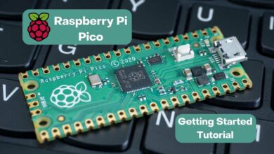
- Getting Started with Raspberry Pi Pico using MicroPython
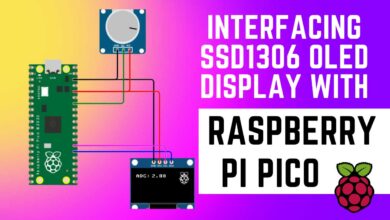
- Interfacing SSD1306 OLED Display with Raspberry Pi Pico
- Read Internal Temperature Sensor Value from Raspberry Pi Pico
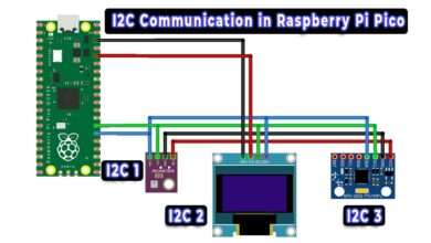
- How to use I2C Pins in Raspberry Pi Pico using MycroPython
- Interfacing BME280 Sensor with Arduino
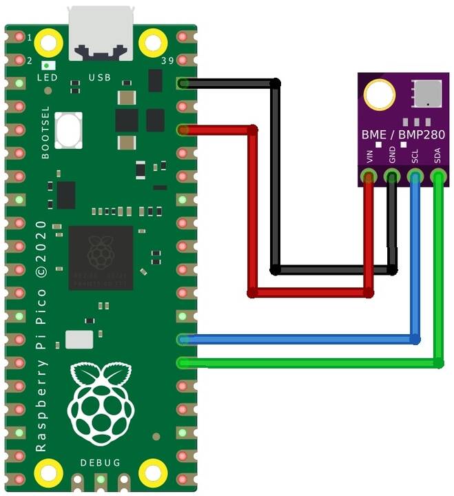
Interfacing BME280 Sensor with Raspberry Pi Pico
To connect the BME280 Sensor with a Raspberry Pi Pico, simply connect the VCC, GND, SCL, and SDA pins of the BME280 Sensor to the 3.3V, GND, GP21, and GP20 pins of the Raspberry Pi Pico respectively. This can be easily achieved by using a breadboard for assembly and testing. The connection process is straightforward.
MicroPython Code: BME280 & Pi Pico Interfacing
The process of interfacing the BME280 Sensor with the Raspberry Pi Pico requires two parts of code: bme280.py and main.py. The main code uses a library for BME280, which includes all the necessary modules and register details to collect data from the sensor.
bme280.py
To use the bme280.py code, open the Thonny IDE and paste the code into the Thonny Editor. Then, save the file on the Raspberry Pi Pico and name it bme280.py.
# Authors: Paul Cunnane 2016, Peter Dahlebrg 2016
#
# This module borrows from the Adafruit BME280 Python library. Original
# Copyright notices are reproduced below.
#
# Those libraries were written for the Raspberry Pi. This modification is
# intended for the MicroPython and esp8266 boards.
#
# Copyright (c) 2014 Adafruit Industries
# Author: Tony DiCola
#
# Based on the BMP280 driver with BME280 changes provided by
# David J Taylor, Edinburgh (www.satsignal.eu)
#
# Based on Adafruit_I2C.py created by Kevin Townsend.
#
# Permission is hereby granted, free of charge, to any person obtaining a copy
# of this software and associated documentation files (the "Software"), to deal
# in the Software without restriction, including without limitation the rights
# to use, copy, modify, merge, publish, distribute, sublicense, and/or sell
# copies of the Software, and to permit persons to whom the Software is
# furnished to do so, subject to the following conditions:
#
# The above copyright notice and this permission notice shall be included in
# all copies or substantial portions of the Software.
#
# THE SOFTWARE IS PROVIDED "AS IS", WITHOUT WARRANTY OF ANY KIND, EXPRESS OR
# IMPLIED, INCLUDING BUT NOT LIMITED TO THE WARRANTIES OF MERCHANTABILITY,
# FITNESS FOR A PARTICULAR PURPOSE AND NONINFRINGEMENT. IN NO EVENT SHALL THE
# AUTHORS OR COPYRIGHT HOLDERS BE LIABLE FOR ANY CLAIM, DAMAGES OR OTHER
# LIABILITY, WHETHER IN AN ACTION OF CONTRACT, TORT OR OTHERWISE, ARISING FROM,
# OUT OF OR IN CONNECTION WITH THE SOFTWARE OR THE USE OR OTHER DEALINGS IN
# THE SOFTWARE.

import time
from ustruct import unpack, unpack_from
from array import array

# BME280 default address.
BME280_I2CADDR = 0x76

# Operating Modes
BME280_OSAMPLE_1 = 1
BME280_OSAMPLE_2 = 2
BME280_OSAMPLE_4 = 3
BME280_OSAMPLE_8 = 4
BME280_OSAMPLE_16 = 5

BME280_REGISTER_CONTROL_HUM = 0xF2
BME280_REGISTER_CONTROL = 0xF4


class BME280:

    def __init__(self,
                 mode=BME280_OSAMPLE_1,
                 address=BME280_I2CADDR,
                 i2c=None,
                 **kwargs):
        # Check that mode is valid.
        if mode not in [BME280_OSAMPLE_1, BME280_OSAMPLE_2, BME280_OSAMPLE_4,
                        BME280_OSAMPLE_8, BME280_OSAMPLE_16]:
            raise ValueError(
                'Unexpected mode value {0}. Set mode to one of '
                'BME280_ULTRALOWPOWER, BME280_STANDARD, BME280_HIGHRES, or '
                'BME280_ULTRAHIGHRES'.format(mode))
        self._mode = mode
        self.address = address
        if i2c is None:
            raise ValueError('An I2C object is required.')
        self.i2c = i2c

        # load calibration data
        dig_88_a1 = self.i2c.readfrom_mem(self.address, 0x88, 26)
        dig_e1_e7 = self.i2c.readfrom_mem(self.address, 0xE1, 7)
        self.dig_T1, self.dig_T2, self.dig_T3, self.dig_P1,
            self.dig_P2, self.dig_P3, self.dig_P4, self.dig_P5,
            self.dig_P6, self.dig_P7, self.dig_P8, self.dig_P9,
            _, self.dig_H1 = unpack("<HhhHhhhhhhhhBB", dig_88_a1)

        self.dig_H2, self.dig_H3 = unpack("<hB", dig_e1_e7)
        e4_sign = unpack_from("<b", dig_e1_e7, 3)[0]
        self.dig_H4 = (e4_sign << 4) | (dig_e1_e7[4] & 0xF)

        e6_sign = unpack_from("<b", dig_e1_e7, 5)[0]
        self.dig_H5 = (e6_sign << 4) | (dig_e1_e7[4] >> 4)

        self.dig_H6 = unpack_from("<b", dig_e1_e7, 6)[0]

        self.i2c.writeto_mem(self.address, BME280_REGISTER_CONTROL,
                             bytearray([0x3F]))
        self.t_fine = 0

        # temporary data holders which stay allocated
        self._l1_barray = bytearray(1)
        self._l8_barray = bytearray(8)
        self._l3_resultarray = array("i", [0, 0, 0])

    def read_raw_data(self, result):
        """ Reads the raw (uncompensated) data from the sensor.

            Args:
                result: array of length 3 or alike where the result will be
                stored, in temperature, pressure, humidity order
            Returns:
                None
        """

        self._l1_barray[0] = self._mode
        self.i2c.writeto_mem(self.address, BME280_REGISTER_CONTROL_HUM,
                             self._l1_barray)
        self._l1_barray[0] = self._mode << 5 | self._mode << 2 | 1
        self.i2c.writeto_mem(self.address, BME280_REGISTER_CONTROL,
                             self._l1_barray)

        sleep_time = 1250 + 2300 * (1 << self._mode)
        sleep_time = sleep_time + 2300 * (1 << self._mode) + 575
        sleep_time = sleep_time + 2300 * (1 << self._mode) + 575
        time.sleep_us(sleep_time)  # Wait the required time

        # burst readout from 0xF7 to 0xFE, recommended by datasheet
        self.i2c.readfrom_mem_into(self.address, 0xF7, self._l8_barray)
        readout = self._l8_barray
        # pressure(0xF7): ((msb << 16) | (lsb << 8) | xlsb) >> 4
        raw_press = ((readout[0] << 16) | (readout[1] << 8) | readout[2]) >> 4
        # temperature(0xFA): ((msb << 16) | (lsb << 8) | xlsb) >> 4
        raw_temp = ((readout[3] << 16) | (readout[4] << 8) | readout[5]) >> 4
        # humidity(0xFD): (msb << 8) | lsb
        raw_hum = (readout[6] << 8) | readout[7]

        result[0] = raw_temp
        result[1] = raw_press
        result[2] = raw_hum

    def read_compensated_data(self, result=None):
        """ Reads the data from the sensor and returns the compensated data.

            Args:
                result: array of length 3 or alike where the result will be
                stored, in temperature, pressure, humidity order. You may use
                this to read out the sensor without allocating heap memory

            Returns:
                array with temperature, pressure, humidity. Will be the one from
                the result parameter if not None
        """
        self.read_raw_data(self._l3_resultarray)
        raw_temp, raw_press, raw_hum = self._l3_resultarray
        # temperature
        var1 = ((raw_temp >> 3) - (self.dig_T1 << 1)) * (self.dig_T2 >> 11)
        var2 = (((((raw_temp >> 4) - self.dig_T1) *
                  ((raw_temp >> 4) - self.dig_T1)) >> 12) * self.dig_T3) >> 14
        self.t_fine = var1 + var2
        temp = (self.t_fine * 5 + 128) >> 8

        # pressure
        var1 = self.t_fine - 128000
        var2 = var1 * var1 * self.dig_P6
        var2 = var2 + ((var1 * self.dig_P5) << 17)
        var2 = var2 + (self.dig_P4 << 35)
        var1 = (((var1 * var1 * self.dig_P3) >> 8) +
                ((var1 * self.dig_P2) << 12))
        var1 = (((1 << 47) + var1) * self.dig_P1) >> 33
        if var1 == 0:
            pressure = 0
        else:
            p = 1048576 - raw_press
            p = (((p << 31) - var2) * 3125) // var1
            var1 = (self.dig_P9 * (p >> 13) * (p >> 13)) >> 25
            var2 = (self.dig_P8 * p) >> 19
            pressure = ((p + var1 + var2) >> 8) + (self.dig_P7 << 4)

        # humidity
        h = self.t_fine - 76800
        h = (((((raw_hum << 14) - (self.dig_H4 << 20) -
                (self.dig_H5 * h)) + 16384)
              >> 15) * (((((((h * self.dig_H6) >> 10) *
                            (((h * self.dig_H3) >> 11) + 32768)) >> 10) +
                          2097152) * self.dig_H2 + 8192) >> 14))
        h = h - (((((h >> 15) * (h >> 15)) >> 7) * self.dig_H1) >> 4)
        h = 0 if h < 0 else h
        h = 419430400 if h > 419430400 else h
        humidity = h >> 12

        if result:
            result[0] = temp
            result[1] = pressure
            result[2] = humidity
            return result

        return array("i", (temp, pressure, humidity))

    @property
    def values(self):
        """ human readable values """

        t, p, h = self.read_compensated_data()

        p = p // 256
        pi = p // 100
        pd = p - pi * 100

        hi = h // 1024
        hd = h * 100 // 1024 - hi * 100
        return ("{}C".format(t / 100), "{}.{:02d}hPa".format(pi, pd),
                "{}.{:02d}%".format(hi, hd))
main.py
Open another tab on Thonny IDE and paste the following code. Save the file as main.py on Raspberry Pi Pico.
from machine import Pin, I2C        #importing relevant modules & classes
from time import sleep
import bme280       #importing BME280 library

i2c=I2C(0,sda=Pin(20), scl=Pin(21), freq=400000)    #initializing the I2C method


while True:
  bme = bme280.BME280(i2c=i2c)          #BME280 object created
  print(bme.values)
  sleep(10)           #delay of 10s
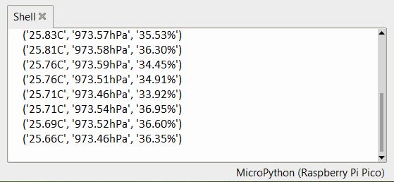
After completing the above steps, execute the main.py file. If the hardware connections have been made correctly, the output of the shell will show the following results.
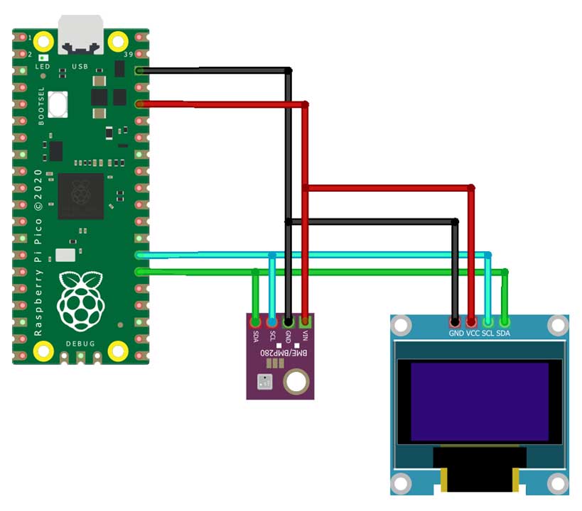
Interfacing BME280 Sensor with Raspberry Pi Pico & OLED Display
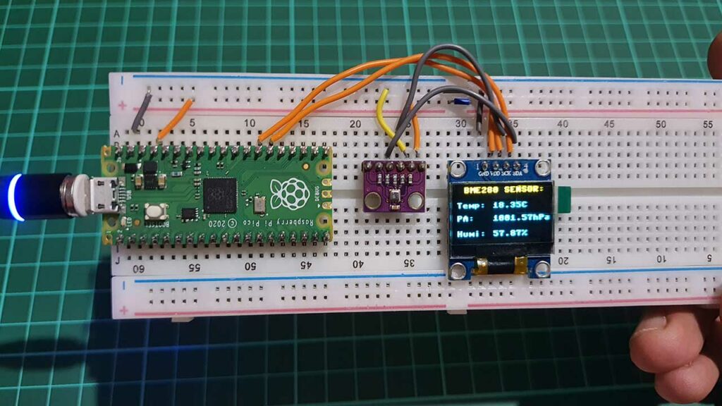
Now, we will cover the process of displaying the sensor readings on a 0.96″ OLED display. The connections are fairly simple to connect the BME280 sensor to the Raspberry Pi Pico and OLED display. Connect the VCC, GND, SCL, and SDA pins of the OLED display to the 3.3V, GND, GP21, and GP20 of the Raspberry Pi Pico respectively. You can use a custom PCB to assemble the circuit and use this project as a mini weather station.
Project PCB Gerber File & PCB Ordering Online
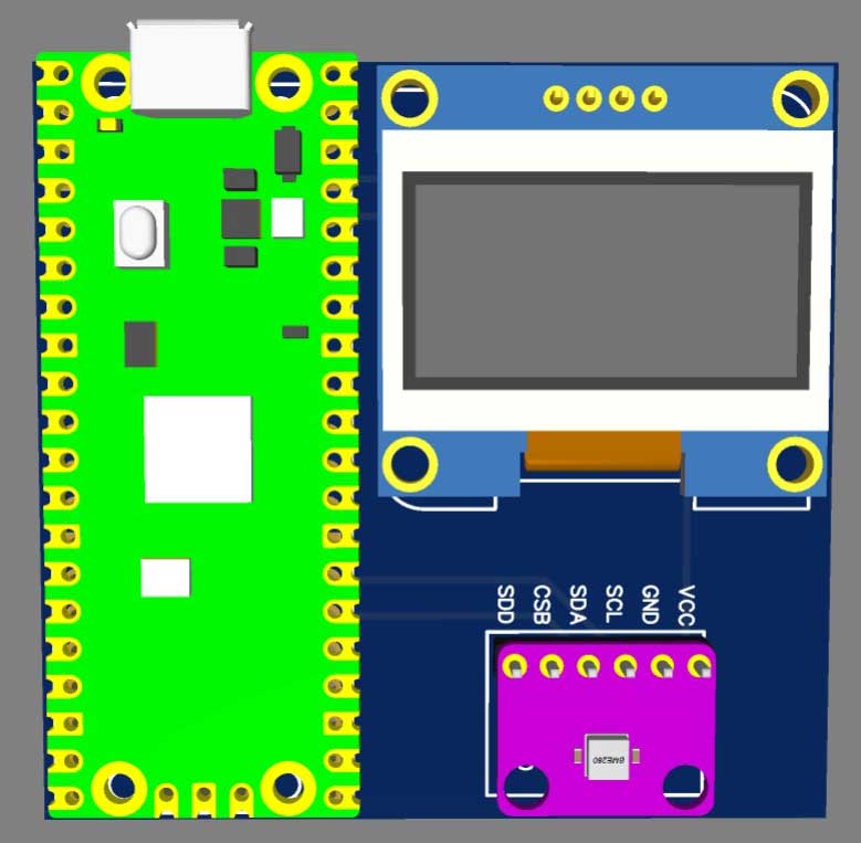
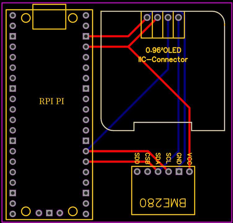
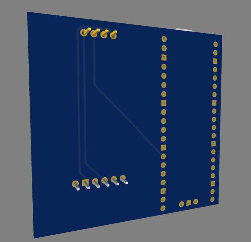
If you don’t want to assemble the circuit on a breadboard and you want PCB for the project, then here is the PCB for you. The PCB Board for this project looks something like below.
The Gerber File for the PCB is given below. You can simply download the Gerber File and order the PCB from PCBWay.com.
Now you can visit the PCBWay official website by clicking here: PCBWay.com. So you will be directed to the PCBWay website.

You can now upload the Gerber File to the Website and place an order. The PCB quality is superb & high standard. That is why most people trust PCBWay for PCB & PCBA Services.
Now, you can assemble the components on the PCB Board.
MicroPython Code: BME280, OLED Display & Pi Pico Interfacing
The process of interfacing the BME280 Sensor with the Raspberry Pi Pico and OLED Display requires three parts of code:
- bme280.py
- ssd1306.py
- main.py.
The main code uses libraries for BME280 and SSD1306 OLED Display. These include all the necessary modules and register details to collect data from the BME280 Sensor and display the reading on a 0.96″ OLED Display. To use the bme280 library, copy the code from above and save it on the Raspberry Pi Pico as bme280.py.
ssd1306.py
Additionally, we also need a library for the SSD1306 OLED Display. Open a new tab on the Thonny IDE and paste the code, then save the file as ssd1306.py on the Raspberry Pi Pico.
# MicroPython SSD1306 OLED driver, I2C and SPI interfaces

from micropython import const
import framebuf

# register definitions
SET_CONTRAST = const(0x81)
SET_ENTIRE_ON = const(0xA4)
SET_NORM_INV = const(0xA6)
SET_DISP = const(0xAE)
SET_MEM_ADDR = const(0x20)
SET_COL_ADDR = const(0x21)
SET_PAGE_ADDR = const(0x22)
SET_DISP_START_LINE = const(0x40)
SET_SEG_REMAP = const(0xA0)
SET_MUX_RATIO = const(0xA8)
SET_COM_OUT_DIR = const(0xC0)
SET_DISP_OFFSET = const(0xD3)
SET_COM_PIN_CFG = const(0xDA)
SET_DISP_CLK_DIV = const(0xD5)
SET_PRECHARGE = const(0xD9)
SET_VCOM_DESEL = const(0xDB)
SET_CHARGE_PUMP = const(0x8D)

# Subclassing FrameBuffer provides support for graphics primitives
# http://docs.micropython.org/en/latest/pyboard/library/framebuf.html
class SSD1306(framebuf.FrameBuffer):
    def __init__(self, width, height, external_vcc):
        self.width = width
        self.height = height
        self.external_vcc = external_vcc
        self.pages = self.height // 8
        self.buffer = bytearray(self.pages * self.width)
        super().__init__(self.buffer, self.width, self.height, framebuf.MONO_VLSB)
        self.init_display()

    def init_display(self):
        for cmd in (
            SET_DISP | 0x00,  # off
            # address setting
            SET_MEM_ADDR,
            0x00,  # horizontal
            # resolution and layout
            SET_DISP_START_LINE | 0x00,
            SET_SEG_REMAP | 0x01,  # column addr 127 mapped to SEG0
            SET_MUX_RATIO,
            self.height - 1,
            SET_COM_OUT_DIR | 0x08,  # scan from COM[N] to COM0
            SET_DISP_OFFSET,
            0x00,
            SET_COM_PIN_CFG,
            0x02 if self.width > 2 * self.height else 0x12,
            # timing and driving scheme
            SET_DISP_CLK_DIV,
            0x80,
            SET_PRECHARGE,
            0x22 if self.external_vcc else 0xF1,
            SET_VCOM_DESEL,
            0x30,  # 0.83*Vcc
            # display
            SET_CONTRAST,
            0xFF,  # maximum
            SET_ENTIRE_ON,  # output follows RAM contents
            SET_NORM_INV,  # not inverted
            # charge pump
            SET_CHARGE_PUMP,
            0x10 if self.external_vcc else 0x14,
            SET_DISP | 0x01,
        ):  # on
            self.write_cmd(cmd)
        self.fill(0)
        self.show()

    def poweroff(self):
        self.write_cmd(SET_DISP | 0x00)

    def poweron(self):
        self.write_cmd(SET_DISP | 0x01)

    def contrast(self, contrast):
        self.write_cmd(SET_CONTRAST)
        self.write_cmd(contrast)

    def invert(self, invert):
        self.write_cmd(SET_NORM_INV | (invert & 1))

    def show(self):
        x0 = 0
        x1 = self.width - 1
        if self.width == 64:
            # displays with width of 64 pixels are shifted by 32
            x0 += 32
            x1 += 32
        self.write_cmd(SET_COL_ADDR)
        self.write_cmd(x0)
        self.write_cmd(x1)
        self.write_cmd(SET_PAGE_ADDR)
        self.write_cmd(0)
        self.write_cmd(self.pages - 1)
        self.write_data(self.buffer)


class SSD1306_I2C(SSD1306):
    def __init__(self, width, height, i2c, addr=0x3C, external_vcc=False):
        self.i2c = i2c
        self.addr = addr
        self.temp = bytearray(2)
        self.write_list = [b"x40", None]  # Co=0, D/C#=1
        super().__init__(width, height, external_vcc)

    def write_cmd(self, cmd):
        self.temp[0] = 0x80  # Co=1, D/C#=0
        self.temp[1] = cmd
        self.i2c.writeto(self.addr, self.temp)

    def write_data(self, buf):
        self.write_list[1] = buf
        self.i2c.writevto(self.addr, self.write_list)


class SSD1306_SPI(SSD1306):
    def __init__(self, width, height, spi, dc, res, cs, external_vcc=False):
        self.rate = 10 * 1024 * 1024
        dc.init(dc.OUT, value=0)
        res.init(res.OUT, value=0)
        cs.init(cs.OUT, value=1)
        self.spi = spi
        self.dc = dc
        self.res = res
        self.cs = cs
        import time

        self.res(1)
        time.sleep_ms(1)
        self.res(0)
        time.sleep_ms(10)
        self.res(1)
        super().__init__(width, height, external_vcc)

    def write_cmd(self, cmd):
        self.spi.init(baudrate=self.rate, polarity=0, phase=0)
        self.cs(1)
        self.dc(0)
        self.cs(0)
        self.spi.write(bytearray([cmd]))
        self.cs(1)

    def write_data(self, buf):
        self.spi.init(baudrate=self.rate, polarity=0, phase=0)
        self.cs(1)
        self.dc(1)
        self.cs(0)
        self.spi.write(buf)
        self.cs(1)
main.py
Now, open a new tab on the Thonny IDE and paste the main.py code. Save the file as main.py on the Raspberry Pi Pico.
from machine import Pin, I2C
from ssd1306 import SSD1306_I2C
import time
import bme280

i2c=I2C(0,sda=Pin(20), scl=Pin(21), freq=400000)    #initializing the I2C method

WIDTH =128
HEIGHT= 64
oled = SSD1306_I2C(WIDTH,HEIGHT,i2c)

while True:
    oled.fill(0)
    bme = bme280.BME280(i2c=i2c)

    print(bme.values)
    oled.text("BME280 SENSOR:", 10, 0)
    oled.text("Temp:", 0, 18)
    oled.text(str(bme.values[0]), 50, 18)
    oled.text("PA:", 0, 35)
    oled.text(str(bme.values[1]), 50, 35)
    oled.text("Humi:", 0, 55)
    oled.text(str(bme.values[2]), 50, 55)
    oled.show()
    time.sleep(1)
Testing
Once the main.py code has been saved, execute it. The OLED display will instantly show the values of temperature, pressure, and humidity. If you are building a weather station, having a display to view the live data is crucial, and the OLED display is an ideal choice for this purpose.
Conclusion
In conclusion, interfacing the BME280 sensor with the Raspberry Pi Pico and OLED Display is a straightforward process that requires three parts of code: bme280.py, ssd1306.py and main.py. These codes use libraries for BME280 and SSD1306 OLED Display that include all the necessary modules and register details to collect data from the BME280 sensor and display the readings on a 0.96″ OLED Display. This project can be a great solution for building a weather station as it provides live data readings of temperature, pressure, and humidity. Hence, the OLED display is an ideal choice for this purpose.