How to use I2C Pins in Raspberry Pi Pico using MycroPython
I2C Scanner Code in Raspberry Pi Pico with MycroPython
The Raspberry Pi Pico is a microcontroller board based on the RP2040 chip. It offers a total of 36 GPIO pins, out of which 26 are multi-function pins that can be used for various purposes such as digital input/output, PWM, I2C, and more. In this tutorial, we will focus on How to use I2C Pins in Raspberry Pi Pico using MycroPython. As well as the usage of two pairs of I2C pins that are available on the board.
I2C, or Inter-Integrated Circuit, is a communication protocol that allows multiple devices to communicate with each other using a shared two-wire interface. The Raspberry Pi Pico has two pairs of I2C pins that can be used to connect and communicate with other I2C devices such as sensors, actuators, and other microcontroller boards.
Get your Raspberry Pi pico learning kit from below.
| S.N | COMPONENTS NAME | QUANTITY | PURCHASE LINKS |
|---|---|---|---|
| 1 | Raspberry Pi Pico Basic Starter Kit | 1 | Amazon | AliExpress |
Overview
To use the I2C pins on the Raspberry Pi Pico, you will need to enable the I2C interface in the firmware and software. Once enabled, you can use the I2C scanner code provided in this tutorial to scan for connected I2C devices and their addresses. This can be useful for debugging and troubleshooting communication issues between devices.
It’s important to note that the remaining 10 GPIO pins on the Raspberry Pi Pico are not exposed, and therefore cannot be used. This is to ensure that the board has a limited number of exposed pins to minimize the risk of electrical damage. And to provide a more compact and portable design.
In summary, this tutorial aims to provide a detailed understanding of how to use I2C pins on the Raspberry Pi Pico microcontroller board, and how to scan for connected I2C devices using the provided I2C scanner code.
In this tutorial, we will discuss the I2C communication protocol and its application on the Raspberry Pi Pico microcontroller board. We will explore how I2C works, including the use of the serial clock line (SCL) and serial data line (SDA) to transmit data between devices.
Additionally, we will delve into the I2C pin of the Raspberry Pi Pico. Then provide an example of using the I2C scanner code to check the I2C addresses of various I2C-enabled sensors and modules. Before diving into the topic, it is recommended to check out our Raspberry Pi Pico Getting Started Tutorial to gain a better understanding of the module.
What is I2C Communication Protocol?
I2C, or Inter-Integrated Circuit, is a synchronous, multi-master, multi-slave, packet-switched, single-ended, serial communication bus. It is a widely used protocol for connecting lower-speed peripheral ICs to processors and microcontrollers in short-distance, intra-board communication. With I2C, only two wires are required to transmit data between devices, the SCL and SDA. The data is sent through the SDA wire and is synchronized with the clock signal from the SCL.
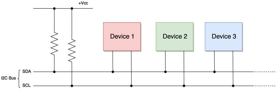
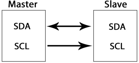
In an I2C network, devices can be either masters or slaves. At any given time, only one master device is active on the bus and controls the SCL clock line. It also decides what operation will be performed on the SDA data line.
The devices that respond to instructions from the master device are considered slaves. To differentiate between multiple slave devices connected to the same I2C bus. Each slave device is assigned a unique 7-bit address.
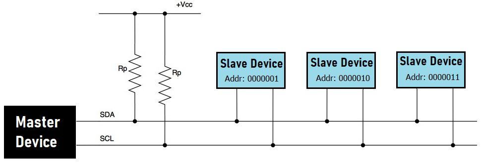
When the master device wants to transfer data to or from a slave device. It specifies the slave device’s address on the SDA line and then proceeds with the transfer. In this way, effective communication takes place between the master and a specific slave device. While all other slave devices remain inactive unless their address is specified by the master.
I2C Pins in Raspberry Pi Pico
The RP2040 chip in the Raspberry Pi Pico microcontroller has two I2C controllers. which can be accessed through the board’s GPIO pins. The table below illustrates the connection of the GPIO pins to both I2C controllers:
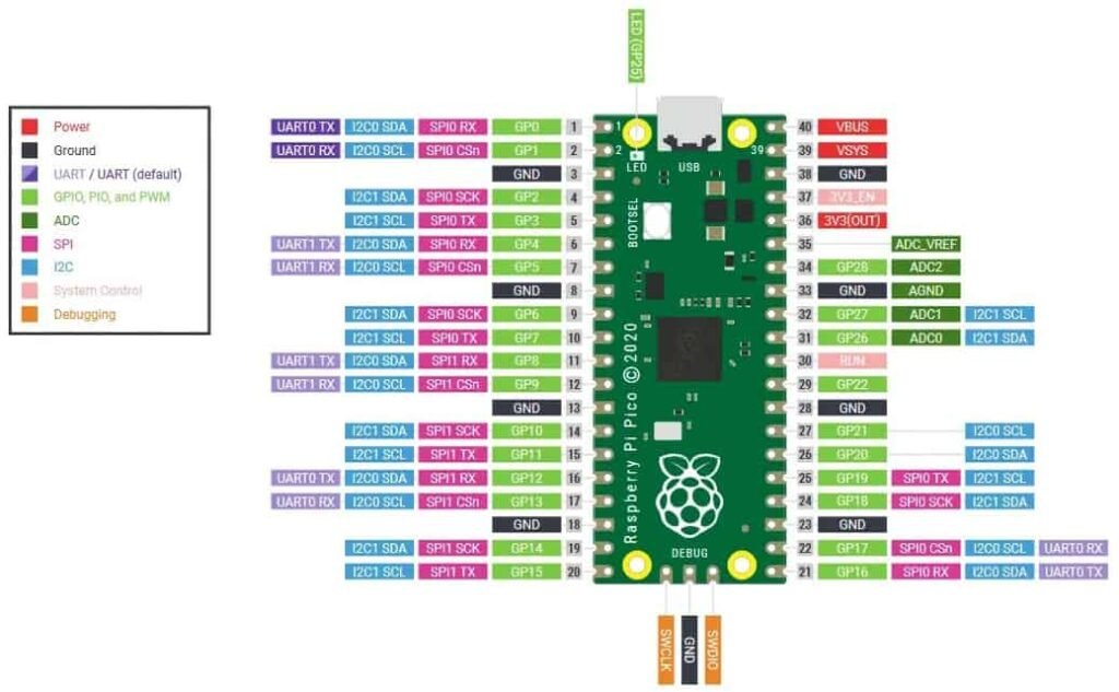
| I2C Controller | GPIO Pins |
| I2C0 – SDA | GP0/GP4/GP8/GP12/GP16/GP20 |
| I2C0 – SCL | GP1/GP5/GP9/GP13/GP17/GP21 |
| I2C1 – SDA | GP2/GP6/GP10/GP14/GP18/GP26 |
| I2C1 – SCL | GP3/GP7/GP11/GP15/GP19/GP27 |
As shown in the table, each I2C controller can be connected to multiple GPIO pins. However, before using an I2C controller, it is necessary to configure in the software which GPIO pins will be used with a specific controller.
Features of Raspberry Pi Pico I2C Pins
The Raspberry Pi Pico, which is built with the RP2040 chip, offers the following features for its I2C pins:
- The device can operate in both master and slave mode, with a default slave address of 0x055.
- The I2C pins have three-speed modes: Standard (0 to 100 Kb/s), Fast(<= 400 Kb/s), and Fast Plus mode (<= 1000 Kb/s).
- The I2C pins have both transmit and receive buffers.
- They can also be used in interrupt and DMA modes.
How to use the I2C Pins of Raspberry Pi Pico with I2C Sensors or Modules?
To use the I2C pins of the Raspberry Pi Pico with other I2C-based sensors or modules. The Pico can be configured as a master device while the external sensors or modules act as slave devices. By using the Raspberry Pi Pico as a master device and other I2C-based sensors or modules as a slave devices. We can communicate with these external devices using the I2C protocol.
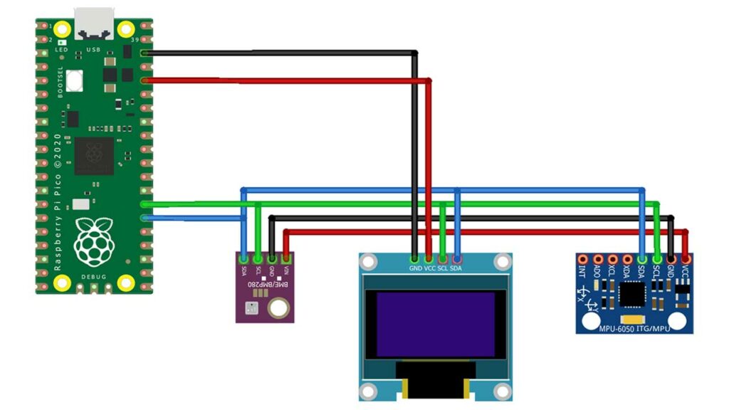
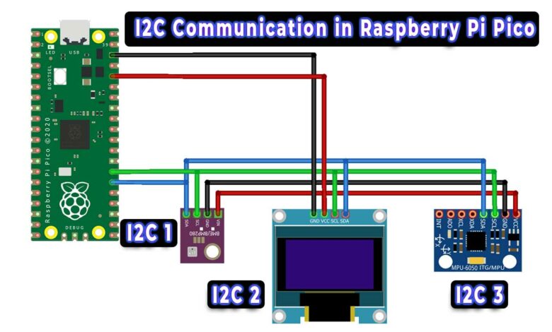
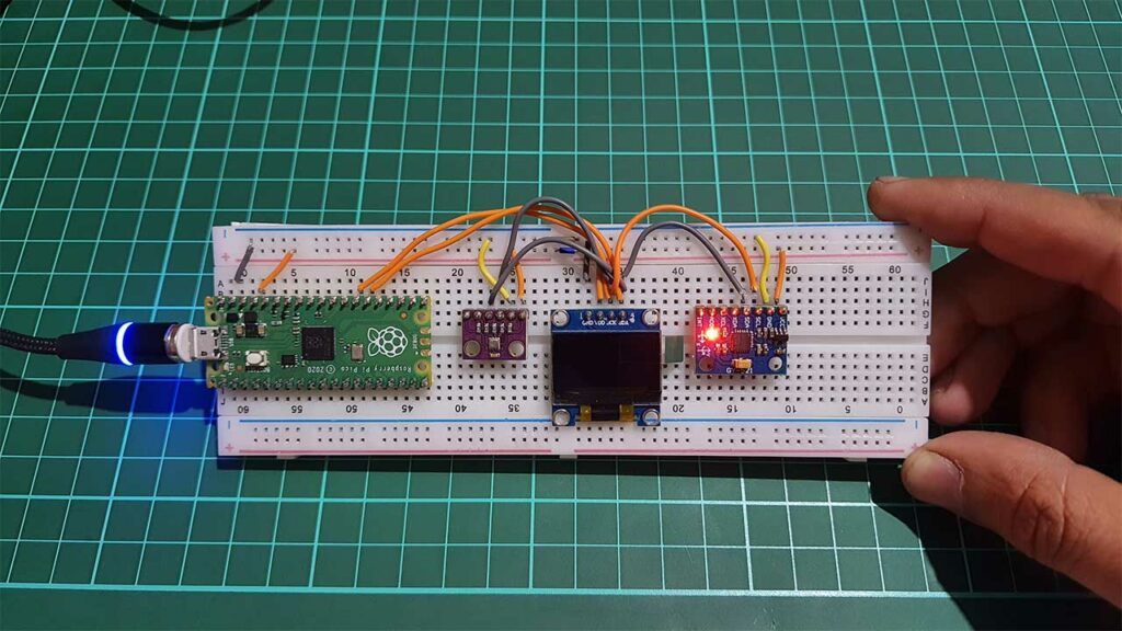
This circuit shows how to connect three different I2C devices to a Raspberry Pi Pico board. The devices include a BME280 sensor, an MPU6050 sensor, and a 0.96″ OLED display. To connect these devices, the SDA and SCL pins of the MPU6050, BME280, and OLED display are connected to a common I2C line on the Raspberry Pi Pico. In this example, only one pair of I2C pins is used on the Raspberry Pi Pico, specifically, GPIO20 for SDA0 and GPIO21 for SCL0.
Raspberry Pi Pico I2C Scanner Code
The following is an example of a Raspberry Pi Pico I2C scanner code written in MicroPython. This code can be used to scan the I2C addresses of all sensors connected to the I2C pins of the Raspberry Pi Pico. The code can be run on an IDE such as Thonny or uPyCraft when the Raspberry Pi Pico is connected to a computer.
import machine
sda=machine.Pin(20)
scl=machine.Pin(21)
i2c=machine.I2C(0,sda=sda, scl=scl, freq=400000)

print('Scan i2c bus...')
devices = i2c.scan()

if len(devices) == 0:
  print("No i2c device !")
else:
  print('i2c devices found:',len(devices))

  for device in devices:
    print("Decimal address: ",device," | Hexa address: ",hex(device))
When the code is run, MicroPython will scan for I2C devices connected to the Raspberry Pi Pico board. Up to 127 I2C slave devices can be connected. The code will scan the addresses and display them in the shell window.
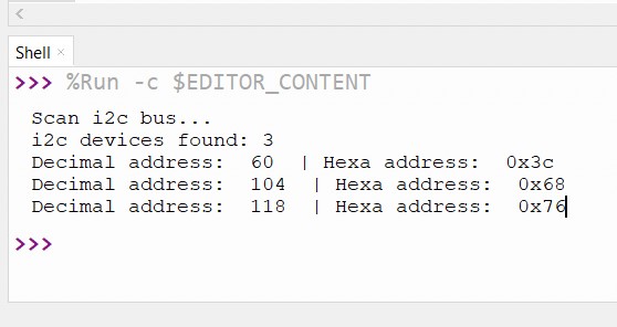
In this example, the I2C address of the OLED display is 60, which in hexadecimal is 0x3C. The I2C address of the MPU6050 is 104, which in hexadecimal is 0x68. The I2C address of the BME280 is 118, which in hexadecimal is 0x76.