Smoke & Gas Leakage Detector using Arduino
MQ2 Sensor Gas & Smoke Leakage Detector Circuit using Arduino
In this project, we will make a smoke and gas leakage detector using Arduino. We have used the MQ2 Gas sensor module to detect Smoke and carbon monoxide concentrations present in Air. MQ2 is a versatile sensor that can detect LPG, smoke, alcohol, propane, hydrogen, methane, carbon monoxide, etc. This makes the MQ2 Gas Sensor Module an excellent choice for building an indoor air quality monitoring system, a breathalyzer, or an early fire detection system.
Overview: Smoke & Gas Detector using Arduino
Smoke and gas leakage detectors are really useful in detecting smoke or fire in buildings. They are important safety parameters in order to avoid disasters. Exploding cylinders and accidental fires have caused lots of damage to houses in the past. This circuit triggers the alarm system when smoke or gas leakage is detected.
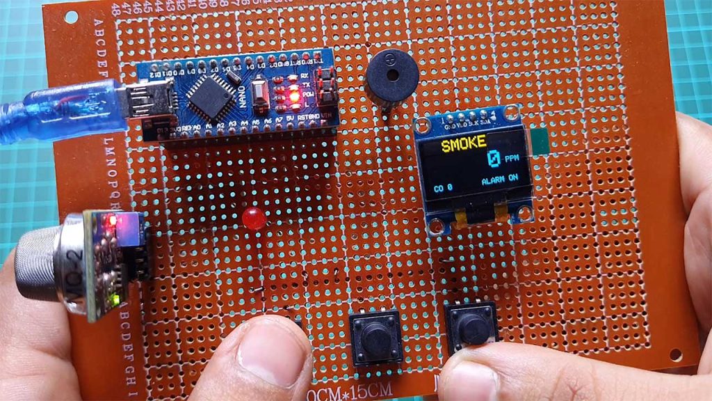
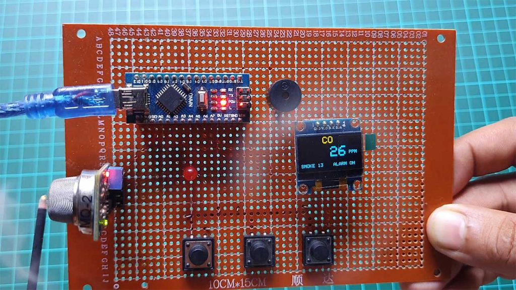
This project has an OLED display to Display the smoke and carbon monoxide concentrations in PPM.
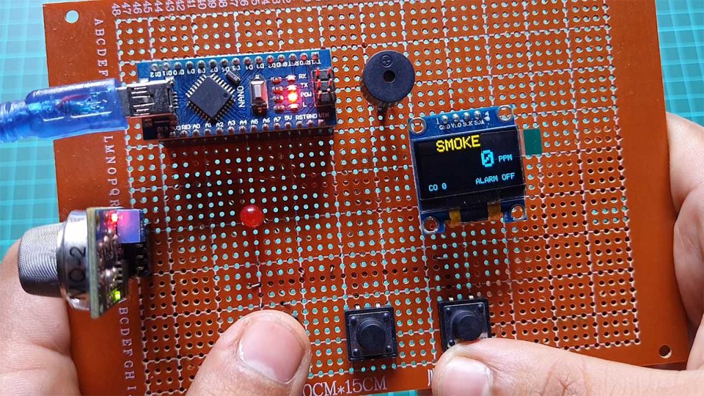
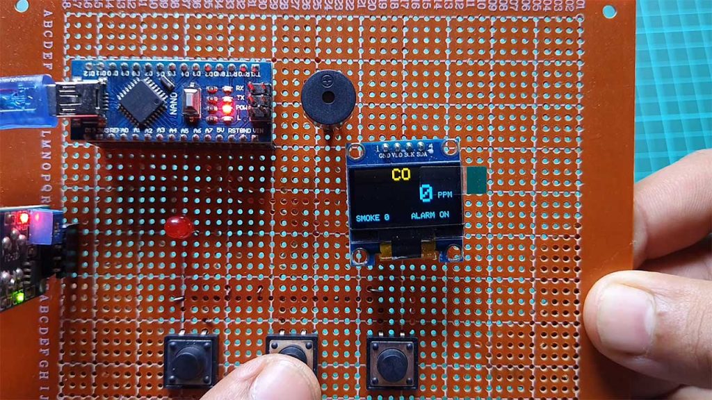
Here we have three push buttons. Among them, the 1st button is used to turn ON and OFF Alarm system. The 2nd and 3rd Buttons help to switch the monitoring screen between Smoke and carbon monoxide.
Working of Arduino based Smoke & Gas Detector
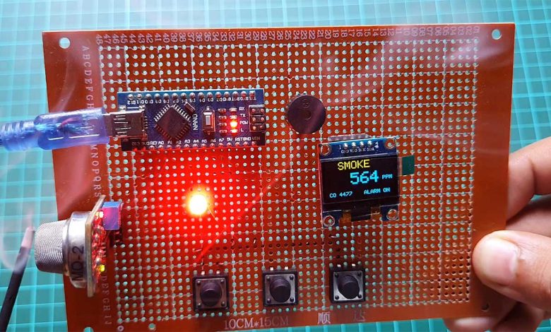
First, let’s see how this project works. The MQ2 sensor detects smoke and Carbon Monoxide values and sends them to Arduino. Arduino then processes these values and displays these values on the OLED display. It also checks if these values are above the safe level then it sends a command to the buzzer and a LED. Then the buzzer starts alarming with a flashing LED.
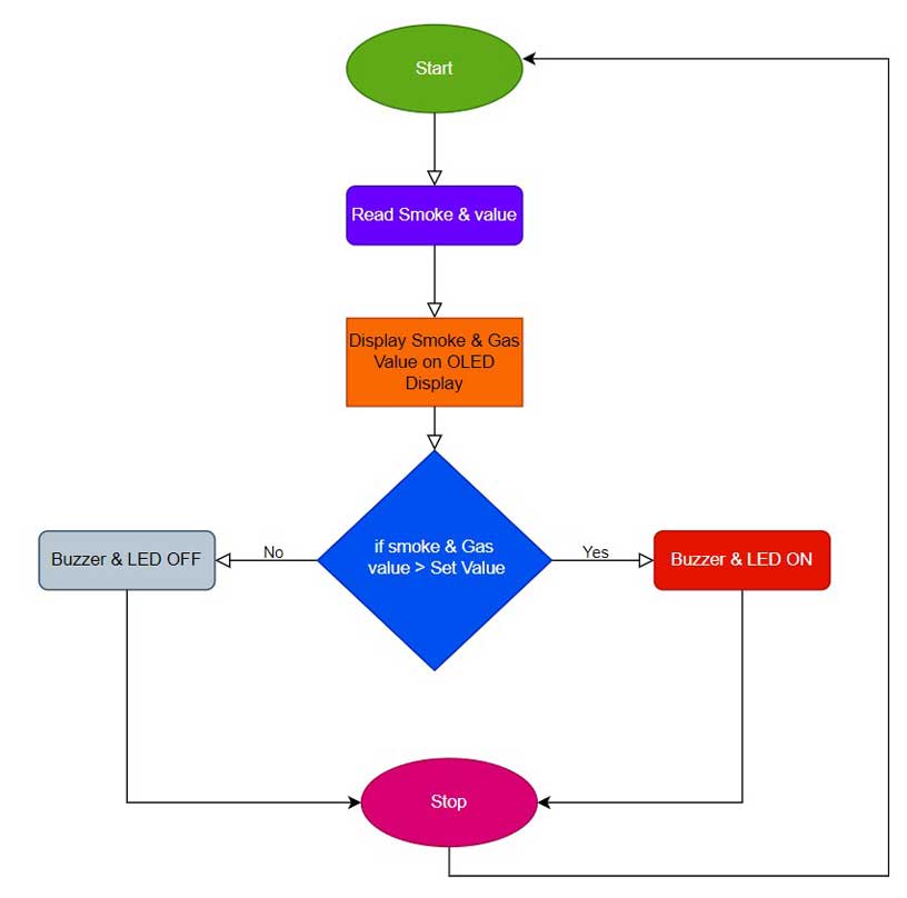
It is a very easy-to-build but very useful project. So without further Ado let’s make this project.
Components Required
These are all the components that are required for making a Smoke & Gas Leakage Detector using Arduino. You can easily purchase them from the Amazon links provided below:
| S.N | Components Name | Quantity | |
|---|---|---|---|
| 1 | Arduino Nano | 1 | https://amzn.to/3FdCNFs |
| 2 | MQ2 Sensor | 1 | https://amzn.to/3FdD2QS |
| 3 | 0.96" I2C OLED Display | 1 | https://amzn.to/3EV50PS |
| 4 | Buzzer | 1 | https://amzn.to/3ipsO6X |
| 5 | 5mm LED | 1 | https://amzn.to/3Fg5LV3 |
| 6 | Zero PCB board | 1 | https://amzn.to/3UmLt0B |
Circuit Diagram: Gas & Smoke Detector
This is the circuit diagram of the Smoke & Gas Leakage Detector using Arduino.
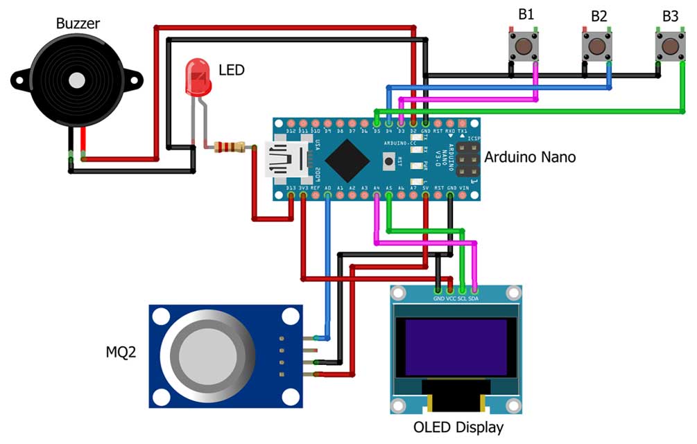
Here I have interfaced the MQ2 sensor Analog Pin A0 pin with the A0 pin of Arduino. VCC and GND are connected to the 5V and GND pins of Arduino respectively. After that, I connected the I2C OLED VCC pin to the 3.3V pin of Arduino and its ground pin to the ground. Its SDA pin to the A4 pin of Arduino and its SCL pin to the A5 pin of Arduino.
After that, I connected an LED anode pin to the D13 pin of Arduino and its cathode pin to the ground. Now, I connected the buzzer’s positive pin to the D2 pin of the Arduino and its negative pin to the Ground pin. Lastly, I have connected three push buttons to the D3, D4, and D5 pins of the Arduino where all other pins are connected to the ground. So I have done all the connections.
Project PCB Gerber File & PCB Ordering Online
If you don’t want to assemble the circuit on a zero PCB and you want PCB for the project, then here is the PCB for you. The PCB Board for this project looks something like below.
The Gerber File for the PCB is given below. You can simply download the Gerber File and order the PCB from PCBWay.com.
Now you can visit the PCBWay official website by clicking here: PCBWay.com. So you will be directed to the PCBWay website.

You can now upload the Gerber File to the Website and place an order. The PCB quality is superb & high standard. That is why most people trust PCBWay for PCB & PCBA Services.
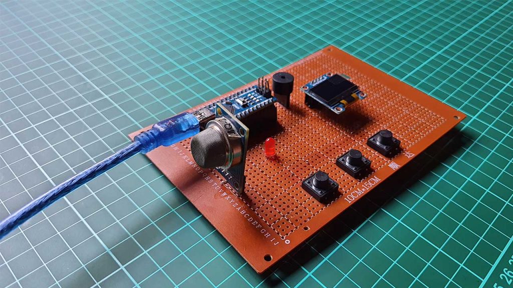
Now, you can assemble the components on the PCB Board.
Program/Source Code
Before you start the programming, first of all, make sure you have downloaded all the necessary libraries and Installed them on your Arduino IDE.
Following is the complete program code for Arduino-based Smoke & Gas Leakage Detector using MQ2 Sensor. Now Copy the following Program code into your Arduino IDE.
// Program/Source Code: Smoke & Gas Leakage Detector using Arduino//
#include <MQ2.h>
#include <SPI.h>
#include <Wire.h>
#include <Adafruit_GFX.h>
#include <Adafruit_SSD1306.h>

#define SCREEN_WIDTH 128 // OLED display width, in pixels
#define SCREEN_HEIGHT 64 // OLED display height, in pixels


#define OLED_RESET     -1 // Reset pin # (or -1 if sharing Arduino reset pin)
#define SCREEN_ADDRESS 0x3C ///< See datasheet for Address; 0x3D for 128x64, 0x3C for 128x32
Adafruit_SSD1306 display(SCREEN_WIDTH, SCREEN_HEIGHT, &Wire, OLED_RESET);
#define B1     3 //14 //D5
#define B2    4 //12 //D6
#define B3   5  //13 //D7
#define BUZZ  2 //2 //D4
#define LED   13 //0 //D3
//change this with the pin that you use
int pin = A0;
int dly1;
float lpg, co, smoke;
long ppm,ppm1,dly,beep;
bool mode,alarm,st;
MQ2 mq2(pin);

void setup(){
  Serial.begin(115200);
  pinMode(B1,INPUT_PULLUP);
  pinMode(B2,INPUT_PULLUP);
  pinMode(B3,INPUT_PULLUP);
  pinMode(BUZZ,OUTPUT);
  pinMode(LED,OUTPUT);
  // calibrate the device
  mq2.begin();

    // SSD1306_SWITCHCAPVCC = generate display voltage from 3.3V internally
  if(!display.begin(SSD1306_SWITCHCAPVCC, SCREEN_ADDRESS)) {
    Serial.println(F("SSD1306 allocation failed"));
    for(;;); // Don't proceed, loop forever
  }
  alarm=1;
}

void loop(){
  dly++;
   dly1++;
if(!digitalRead(B1)&digitalRead(B2)){
  mode=0;
  }
if(digitalRead(B1)&!digitalRead(B2)){
  mode=1;
  }
 if(digitalRead(B3))st=0;
if(!digitalRead(B3)&!st){
  st=1;
  alarm=!alarm;
  }
float* values= mq2.read(true); //set it false if you don't want to print the values to the Serial


  co = mq2.readCO();

  smoke = mq2.readSmoke();
  ppm=smoke;
  ppm1=co;


 display.clearDisplay();

  display.setTextSize(2);             // Normal 1:1 pixel scale
  display.setTextColor(SSD1306_WHITE);        // Draw white text
  display.setCursor(0,0);             // Start at top-left corner
   if(mode) display.println(F("    CO    "));
    else display.println(F("  SMOKE   "));
  display.setTextSize(3);             // Draw 2X-scale text
  display.setTextColor(SSD1306_WHITE);
  display.setCursor(10,20);
   if(mode) {if(ppm1<10000)display.print(F(" "));
    else display.print(ppm1/10000);
    if(ppm1<1000)display.print(F(" "));
    else display.print((ppm1/1000)%10);
    if(ppm1<100)display.print(F(" "));
    else display.print((ppm1/100)%10);
    if(ppm1<10)display.print(F(" "));
    else display.print((ppm1/10)%10);
     display.print(ppm1%10);}
 else {if(ppm<10000)display.print(F(" "));
    else display.print(ppm/10000);
    if(ppm<1000)display.print(F(" "));
    else display.print((ppm/1000)%10);
    if(ppm<100)display.print(F(" "));
    else display.print((ppm/100)%10);
    if(ppm<10)display.print(F(" "));
    else display.print((ppm/10)%10);
     display.print(ppm%10);}

display.setTextSize(1);             // Normal 1:1 pixel scale
  display.setTextColor(SSD1306_WHITE);        // Draw white text
  display.setCursor(105,30);             // Start at top-left corner
  display.println(F("PPM"));
             // Normal 1:1 pixel scale
  display.setTextColor(SSD1306_WHITE);        // Draw white text
  display.setCursor(0,55);             // Start at top-left corner
 if(mode){ display.print(F("SMOKE "));
           display.print(ppm);}
    else{ display.print(F(" CO "));
    display.print(ppm1);
     }
  display.setCursor(64,55);
  if(alarm)display.println(F(" ALARM ON"));
  else display.println(F(" ALARM OFF"));

  display.display();


  beep=50000/ppm1;
  if(beep<10)beep=10;
  if(ppm1>beep){
   if(alarm){ digitalWrite(BUZZ,1);digitalWrite(LED,1);}
    delay(100);
    digitalWrite(BUZZ,0);digitalWrite(LED,0);
    }
  delay(100);
}
Program Code Explanation
Here we included all the required library header files. MQ2 library to get Smoke and Gas Value. SPI and Wire library for sensor & Display communication with Arduino. Adafruit SSD1306 and GFX library for OLED Display.
#include <MQ2.h>
#include <SPI.h>
#include <Wire.h>
#include <Adafruit_GFX.h>
#include <Adafruit_SSD1306.h>
Here we configured our 0.96-inch SSD1306 OLED Display with its height, width, reset pin, I2C address, etc.
#define SCREEN_WIDTH 128 // OLED display width, in pixels
#define SCREEN_HEIGHT 64 // OLED display height, in pixels
#define OLED_RESET     -1 // Reset pin # (or -1 if sharing Arduino reset pin)
#define SCREEN_ADDRESS 0x3C ///< See datasheet for Address; 0x3D for 128x64, 0x3C for 128x32
Adafruit_SSD1306 display(SCREEN_WIDTH, SCREEN_HEIGHT, &Wire, OLED_RESET);
Define your Arduino pins in which Sensor, buzzer, LED, and buttons are connected. Change this with the pin that you use. Then we defined some variables to store values.
#define B1     3
#define B2    4
#define B3   5
#define BUZZ  2
#define LED   13
int pin = A0;
int dly1;
float lpg, co, smoke;
long ppm,ppm1,dly,beep;
bool mode,alarm,st;
MQ2 mq2(pin);
In void setup, we initialize the serial monitor, OLED Display, LED, Buzzer, & Buttons. Then Calibrate the MQ2 Sensor.
 Serial.begin(115200);
  pinMode(B1,INPUT_PULLUP);
  pinMode(B2,INPUT_PULLUP);
  pinMode(B3,INPUT_PULLUP);
  pinMode(BUZZ,OUTPUT);
  pinMode(LED,OUTPUT);
  // calibrate the device
  mq2.begin();

    // SSD1306_SWITCHCAPVCC = generate display voltage from 3.3V internally
  if(!display.begin(SSD1306_SWITCHCAPVCC, SCREEN_ADDRESS)) {
    Serial.println(F("SSD1306 allocation failed"));
    for(;;); // Don't proceed, loop forever
  }
  alarm=1;
In the loop section, we read the button state and display different modes on OLED Display. Then We calculate Smoke and CO from the MQ2 sensor and store those values on ppm and ppm1 variables. Now, Arduino sends these values to the OLED Display for Monitoring. At the same time, It also checks if these values are above the safe level then it sends a command to the buzzer and a LED. IF values are above safe levels then the buzzer starts alarming with a flashing LED.
void loop(){
  dly++;
   dly1++;
if(!digitalRead(B1)&digitalRead(B2)){
  mode=0;
  }
if(digitalRead(B1)&!digitalRead(B2)){
  mode=1;
  }
 if(digitalRead(B3))st=0;
if(!digitalRead(B3)&!st){
  st=1;
  alarm=!alarm;
  }
float* values= mq2.read(true); //set it false if you don't want to print the values to the Serial


  co = mq2.readCO();

  smoke = mq2.readSmoke();
  ppm=smoke;
  ppm1=co;


 display.clearDisplay();

  display.setTextSize(2);             // Normal 1:1 pixel scale
  display.setTextColor(SSD1306_WHITE);        // Draw white text
  display.setCursor(0,0);             // Start at top-left corner
   if(mode) display.println(F("    CO    "));
    else display.println(F("  SMOKE   "));
  display.setTextSize(3);             // Draw 2X-scale text
  display.setTextColor(SSD1306_WHITE);
  display.setCursor(10,20);
   if(mode) {if(ppm1<10000)display.print(F(" "));
    else display.print(ppm1/10000);
    if(ppm1<1000)display.print(F(" "));
    else display.print((ppm1/1000)%10);
    if(ppm1<100)display.print(F(" "));
    else display.print((ppm1/100)%10);
    if(ppm1<10)display.print(F(" "));
    else display.print((ppm1/10)%10);
     display.print(ppm1%10);}
 else {if(ppm<10000)display.print(F(" "));
    else display.print(ppm/10000);
    if(ppm<1000)display.print(F(" "));
    else display.print((ppm/1000)%10);
    if(ppm<100)display.print(F(" "));
    else display.print((ppm/100)%10);
    if(ppm<10)display.print(F(" "));
    else display.print((ppm/10)%10);
     display.print(ppm%10);}

display.setTextSize(1);             // Normal 1:1 pixel scale
  display.setTextColor(SSD1306_WHITE);        // Draw white text
  display.setCursor(105,30);             // Start at top-left corner
  display.println(F("PPM"));
             // Normal 1:1 pixel scale
  display.setTextColor(SSD1306_WHITE);        // Draw white text
  display.setCursor(0,55);             // Start at top-left corner
 if(mode){ display.print(F("SMOKE "));
           display.print(ppm);}
    else{ display.print(F(" CO "));
    display.print(ppm1);
     }
  display.setCursor(64,55);
  if(alarm)display.println(F(" ALARM ON"));
  else display.println(F(" ALARM OFF"));

  display.display();


  beep=50000/ppm1;
  if(beep<10)beep=10;
  if(ppm1>beep){
   if(alarm){ digitalWrite(BUZZ,1);digitalWrite(LED,1);}
    delay(100);
    digitalWrite(BUZZ,0);digitalWrite(LED,0);
    }
  delay(100);
}
Uploading Code & Testing Project
Now select your Arduino board and Its COM Port. Then hit that upload button. It takes a few seconds to compile and upload the code. So to test this smoke detector.
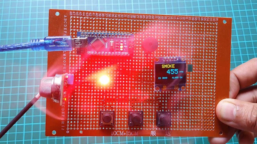
I am producing some smoke through this external source. As the value rises above the safe threshold. The Buzzer alarms with a flashing RED LED as an Alert system.
You can also turn ON and OFF the Alarm using this button.
Video Tutorial & Guide
Conclusion
Alright, that’s all for the MQ2 Sensor as a Smoke & Gas Leakage Detector using Arduino project. The complete project details including device information purchase link source code and written guide are provided for you. In case you have any other questions you can comment in the comment section below. Thank you so much for Visiting.


what is this variable int dly1