Interface Stone HMI Display with Arduino
Smart Home Project Using STONE HMI Display & Arduino
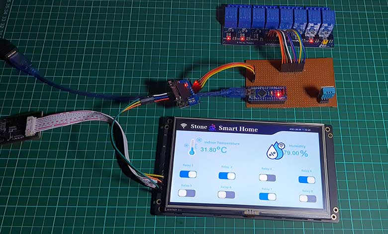
Overview: Smart Home with Stone HMI Display & Arduino
Today, in this tutorial, we will learn how to interface Stone HMI Touch Display with Arduino for a smart home project. In our previous tutorials, we learned basics about the fundamentals of the Stone HMI Display and designed a visually appealing user-friendly interface using the Stone Designer software. Now, in this session, we will go deeper and learn how to establish a connection between the Stone HMI Touch Display and the Arduino microcontroller.
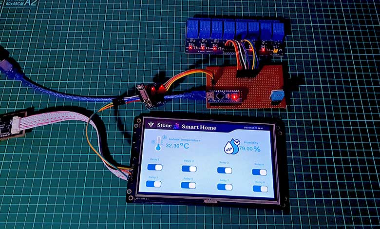
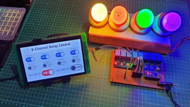
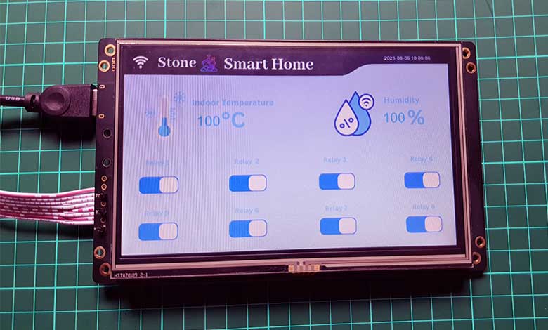
After this tutorial, you will be able to control relays and monitor dht11/dht22 temperature and humidity sensor data on Stone HMI Touch Display. With this system, you can easily manage your smart devices and appliances, for a seamless experience. Whether controlling lights, and fans or monitoring indoor climate conditions, this project is a fully functional smart home system. Get creative, explore new ideas, and turn your home into a smart home with the power of Stone HMI Display and Arduino integration!
Stone HMI Displays are popular choices for smart home projects due to their reliability, easy to use, and cost-effectiveness. These displays offer a high-quality graphical interface. So, it is perfect for visualizing data and controlling various devices in a smart home setup. With the Stone HMI Display, you can design interactive user interfaces with buttons, labels, switches, and more.
Components Required
Before we start, here’s a list of the components you’ll need for this project:
| S.N | COMPONENTS NAME | QUANTITY | PURCHASE LINKS |
|---|---|---|---|
| 1 | Stone HMI Display (STWI070WT-01) | 1 | Amazon | AliExpress |
| 2 | WS2812 LED Strip | 1 | Amazon | AliExpress |
| 3 | Arduino Nano | 1 | Amazon | AliExpress |
| 4 | DHT11 Temperature & Humidity Sensor | 1 | Amazon | AliExpress |
| 5 | 8 Channel 5V relay Module | 1 | Amazon | AliExpress |
| 6 | MAX3232 RS232 to TTL | 1 | Amazon | AliExpress |
| 7 | Type A USB Cable | 5 | Amazon | AliExpress |
- Stone HMI Display: Choose a suitable size and resolution that fits your requirements.
- Arduino Board: We will use an Arduino Nano in this example.
- DHT11/DHT22 Temperature and Humidity Sensor: For monitoring indoor climate conditions.
- 8-Channel Relay Module: To control multiple appliances or devices.
- RS232 to TTL Converter Module: For communication between the Stone HMI Display and Arduino.
- Connecting Wires: To interconnect all the components.
- Power Supply: To power the Stone HMI Display and the relay module.
Interfacing Stone HMI Display DHT11 & Relays with Arduino
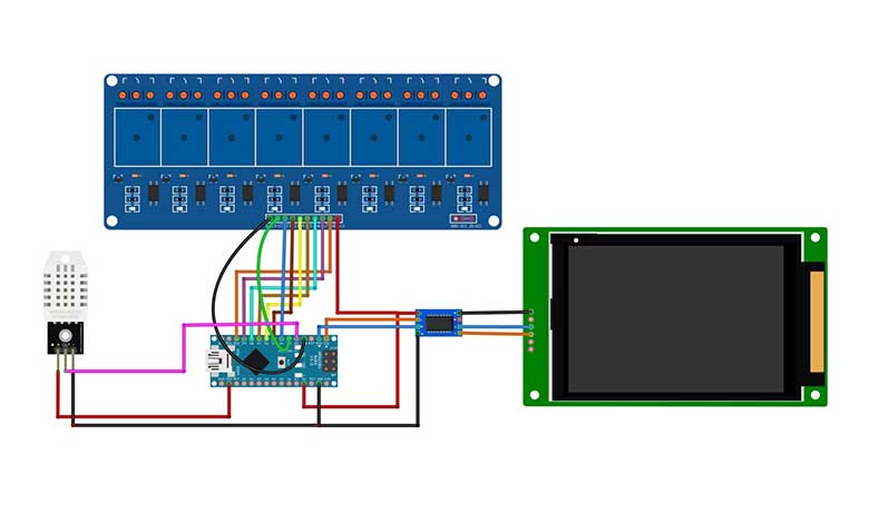
Connect the Stone HMI Display to the Arduino Nano using the RS232 to TTL Converter Module. Ensure that the communication pins (TX & RX) are correctly connected between the display and the converter module.
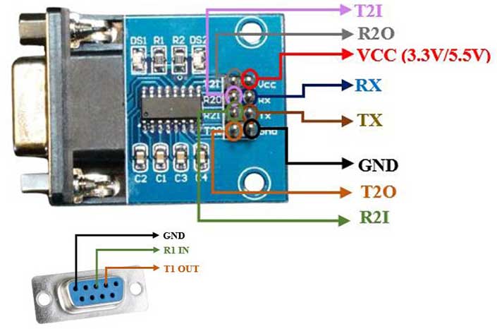
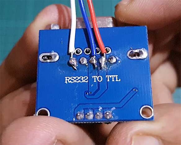
You solder three jumpers to the back side of the RS232 to the TTL converter module for easy connection with the display.
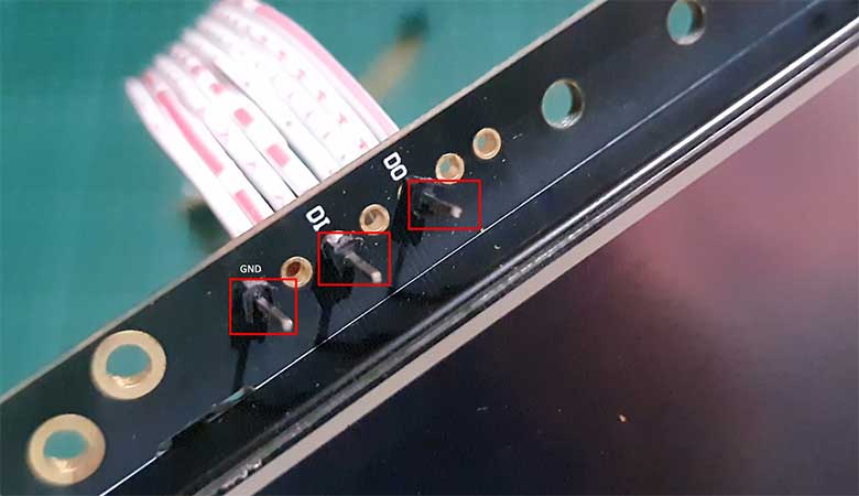
Also, solder three header pins (GND, TX, and RX) on the Stone HMI Display as shown below.
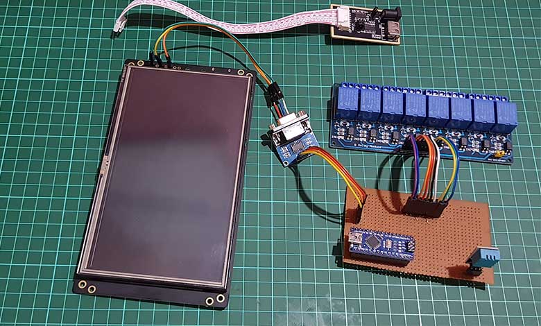
While interfacing RS232 to the TTL module with Arduino you need to connect the TX pin to TX and RX pin to the RX pin of the Arduino. But for the output display, connect TX to RX and RX to TX pins.

- Connect the DHT11 Sensor to the Arduino Nano. The data pin of the DHT11 should be connected to a digital pin D2 on the Arduino.
- Connect the 8-Channel Relay Module to the Arduino Nano digital pins D3, D4, D5, D6, D7, D8, D9, and D10 to control each relay channel.
- Power the Stone HMI Display and the relay module using the USB to UART module with a 12V DC power supply.
PCB Design, Gerber Files & PCB Ordering
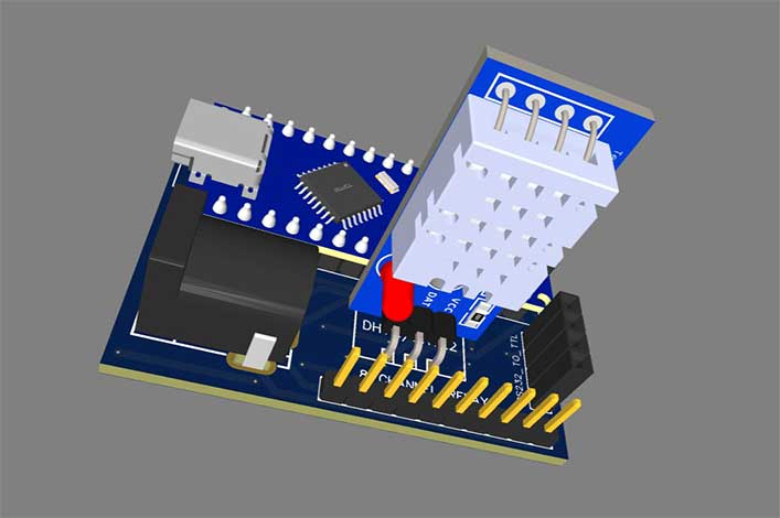
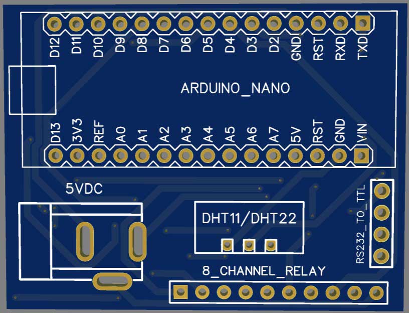
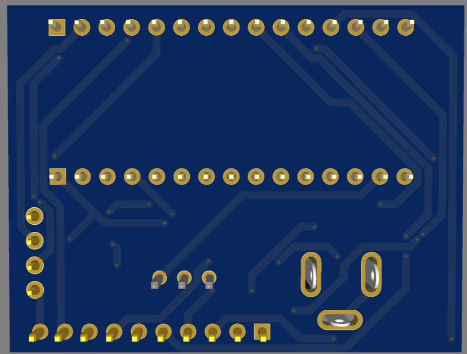
To assemble the components for testing, you can use a breadboard. However, for a more reliable and professional solution, I recommend using a custom PCB. I have already designed a custom PCB specifically for this project.
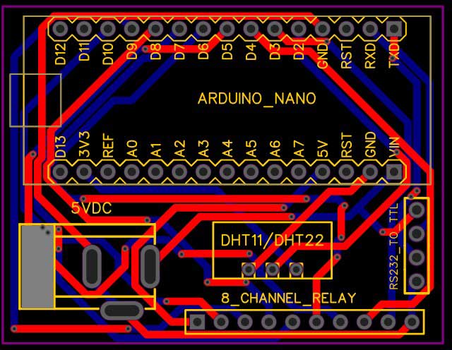
To access the Gerber file of the PCB, you can download it from the provided link.
Once you have the Gerber file, you can place an order for the PCB from PCBWay.com. PCBWay offers affordable prices and provides high-quality PCB manufacturing services. They have exciting offers such as a new user signup bonus and various coupons that you can take advantage of for your order.
Software Setup
First, you need to design User Interface for your Stone HMI Touch Display on the Stone Designer Software. Create buttons, labels, and switches as per your smart home project requirements. Ensure that you assign appropriate commands for the buttons and switches to control the relay channels. We already covered how to design a custom UI for your display using stone designer software in our previous tutorial. So, we are going to use the same project UI for reading and monitoring data with the Arduino microcontroller.
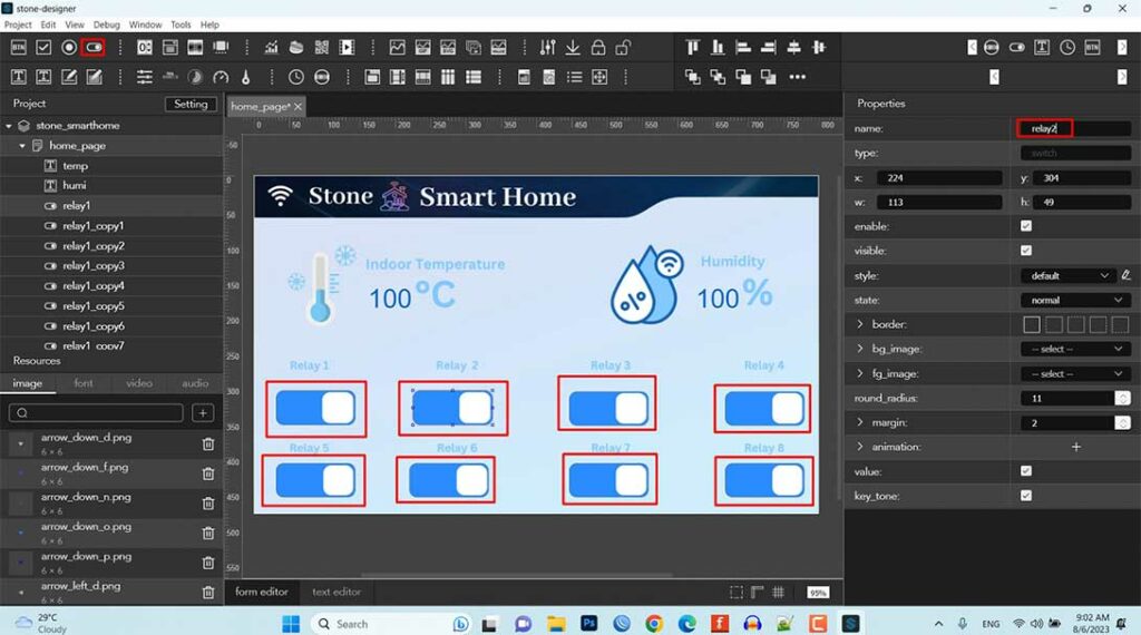
So, if you are new to Stone HMI display then make sure you go through these getting started tutorials first.
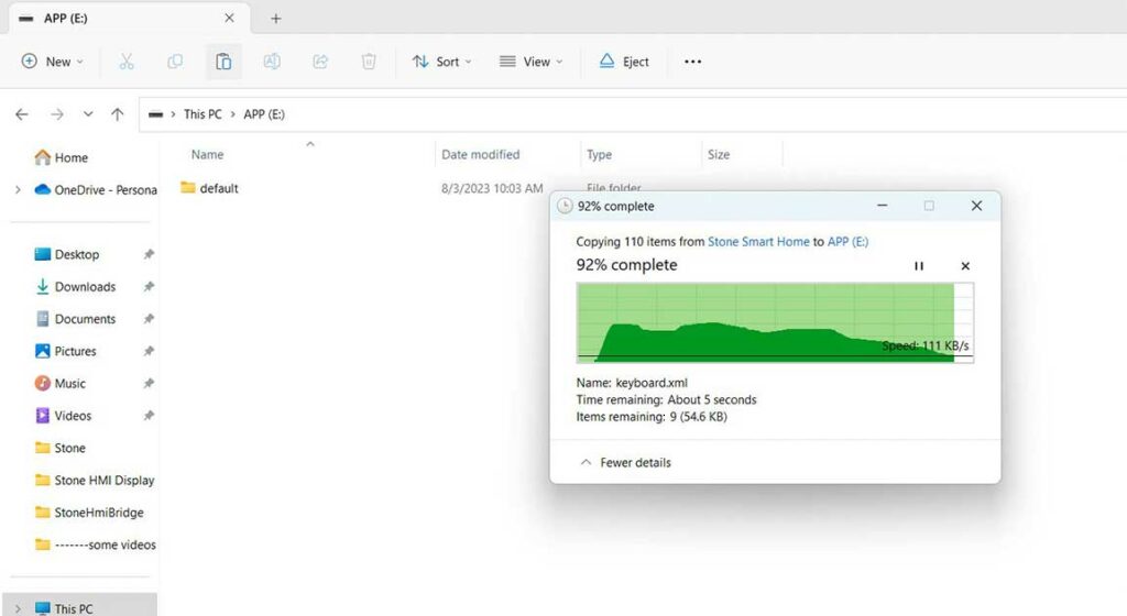
Now, Download the UI file from Stone Designer Software and upload it to the Stone HMI Display using USB to UART Module.
For an Arduino part, you need to install the required libraries on your Arduino IDE: ArduinoJson and DHT Library.
Then Upload the Arduino code provided in this blog post to your Arduino Nano. This code will read temperature and humidity values from the DHT11 sensor and control the relay channels based on UART commands received from the Stone HMI Display.
Arduino Program Code
This code allows you to control the 8-channel relay module based on the received UART commands. It also sends temperature and humidity data to the Stone HMI Display for visualization and monitoring purposes. The HMI display will show real-time temperature and humidity values updated every second. The Stone HMI Display will parse the JSON data received through UART and update the corresponding label widgets with the temperature and humidity values.
#include <ArduinoJson.h> // Include the ArduinoJson library (install it from Arduino Library Manager)
#include <DHT.h>        // Include the DHT sensor library

#define DHT_PIN 2       // Pin connected to DHT11 sensor
#define DHT_TYPE DHT11  // Change to DHT22 if using DHT22 sensor

unsigned char Buffer[20];

#define Relay1 3
#define Relay2 4
#define Relay3 5
#define Relay4 6
#define Relay5 7
#define Relay6 8
#define Relay7 9
#define Relay8 10

DHT dht(DHT_PIN, DHT_TYPE); // Initialize the DHT sensor

float tempr = 0.0;
float humid = 0.0;

char TxData[100];

void setup() {
  Serial.begin(115200);
  pinMode(Relay1, OUTPUT);
  pinMode(Relay2, OUTPUT);
  pinMode(Relay3, OUTPUT);
  pinMode(Relay4, OUTPUT);
  pinMode(Relay5, OUTPUT);
  pinMode(Relay6, OUTPUT);
  pinMode(Relay7, OUTPUT);
  pinMode(Relay8, OUTPUT);

  dht.begin(); // Initialize the DHT sensor
}

void loop() {
  if (Serial.available()) {
    /* This loop will store the whole frame in the buffer array */
    for (int i = 0; i <= 19; i++) {
      Buffer[i] = Serial.read();
    }

    /* Checking first index of the frame as it is 0x53 */
    if (Buffer[0] == 0x53) {
      /* Checking condition for Relay- 1 [ON] at frame index 18 with value 0xEC */
      if (Buffer[18] == 0xEC) {
        Serial.println("Relay1_ON");
        digitalWrite(Relay1, LOW);
      }
      /* Checking condition for Relay- 1 [OFF] at frame index 18 with value 0xED */
      else if (Buffer[18] == 0xED) {
        Serial.println("Relay1_OFF");
        digitalWrite(Relay1, HIGH);
      }
      /* Checking condition for Relay-2 [ON] at frame index 18 with value 0xA8 */
      else if (Buffer[18] == 0xA8) {
        Serial.println("Relay2_ON");
        digitalWrite(Relay2, LOW);
      }
      /* Checking condition for Relay-2 [OFF] at frame index 18 with value 0xA9 */
      else if (Buffer[18] == 0xA9) {
        Serial.println("Relay2_OFF");
        digitalWrite(Relay2, HIGH);
      }
      /* Checking condition for Relay-3 [ON] at frame index 18 with value 0x95 */
      else if (Buffer[18] == 0x95) {
        Serial.println("Relay3_ON");
        digitalWrite(Relay3, LOW);
      }
      /* Checking condition for Relay-3 [OFF] at frame index 18 with value 0x94 */
      else if (Buffer[18] == 0x94) {
        Serial.println("Relay3_OFF");
        digitalWrite(Relay3, HIGH);
      }
      /* Checking condition for Relay-4 [ON] at frame index 18 with value 0x20 */
      else if (Buffer[18] == 0x20) {
        Serial.println("Relay4_ON");
        digitalWrite(Relay4, LOW);
      }
      /* Checking condition for Relay-4 [OFF] at frame index 18 with value 0x21 */
      else if (Buffer[18] == 0x21) {
        Serial.println("Relay4_OFF");
        digitalWrite(Relay4, HIGH);
      }
      /* Checking condition for Relay-5 [ON] at frame index 18 with value 0x1D */
      else if (Buffer[18] == 0x1D) {
        Serial.println("Relay5_ON");
        digitalWrite(Relay5, LOW);
      }
      /* Checking condition for Relay-5 [OFF] at frame index 18 with value 0x1C */
      else if (Buffer[18] == 0x1C) {
        Serial.println("Relay5_OFF");
        digitalWrite(Relay5, HIGH);
      }
      /* Checking condition for Relay-6 [ON] at frame index 18 with value 0x59 */
      else if (Buffer[18] == 0x59) {
        Serial.println("Relay6_ON");
        digitalWrite(Relay6, LOW);
      }
      /* Checking condition for Relay-6 [OFF] at frame index 18 with value 0x58 */
      else if (Buffer[18] == 0x58) {
        Serial.println("Relay6_OFF");
        digitalWrite(Relay6, HIGH);
      }
      /* Checking condition for Relay-7 [ON] at frame index 18 with value 0x64 */
      else if (Buffer[18] == 0x64) {
        Serial.println("Relay7_ON");
        digitalWrite(Relay7, LOW);
      }
      /* Checking condition for Relay-7 [OFF] at frame index 18 with value 0x65 */
      else if (Buffer[18] == 0x65) {
        Serial.println("Relay7_OFF");
        digitalWrite(Relay7, HIGH);
      }
      /* Checking condition for Relay-8 [ON] at frame index 18 with value 0x30 */
      else if (Buffer[18] == 0x30) {
        Serial.println("Relay8_ON");
        digitalWrite(Relay8, LOW);
      }
      /* Checking condition for Relay-8 [OFF] at frame index 18 with value 0x31 */
      else if (Buffer[18] == 0x31) {
        Serial.println("Relay8_OFF");
        digitalWrite(Relay8, HIGH);
      }
    }
  }

  // Read temperature and humidity from the DHT sensor
  tempr = dht.readTemperature();
  humid = dht.readHumidity();

  // Update temperature and humidity data on the Stone HMI display
  StaticJsonDocument<100> jsonDoc;
  jsonDoc["cmd_code"] = "set_value";
  jsonDoc["type"] = "label";
  jsonDoc["widget"] = "temp";

  // Use dtostrf to convert float values to character arrays with two decimal places
  char tempStr[10];
  char humidStr[10];
  dtostrf(tempr, 4, 2, tempStr); // 4 is the total width, 2 is the decimal places
  dtostrf(humid, 4, 2, humidStr); // 4 is the total width, 2 is the decimal places

  jsonDoc["value"] = atof(tempStr); // Convert back to float for JSON
  jsonDoc["format"] = "%.2f";

  serializeJson(jsonDoc, TxData);
  Serial.write("ST<");
  Serial.write(TxData);
  Serial.write(">ETn");

  jsonDoc.clear();
  jsonDoc["cmd_code"] = "set_value";
  jsonDoc["type"] = "label";
  jsonDoc["widget"] = "humi";
  jsonDoc["value"] = atof(humidStr); // Convert back to float for JSON
  jsonDoc["format"] = "%.2f";

  serializeJson(jsonDoc, TxData);
  Serial.write("ST<");
  Serial.write(TxData);
  Serial.write(">ETn");

  delay(1000); // Update the data every 1 second (adjust as needed)
}
Arduino Program Code Explanation
This Arduino code is designed to control an 8-channel relay module and send data (temperature and humidity values) to a Stone HMI Display using UART communication. Let’s break down the code:
The required libraries are included: ArduinoJson.h for working with JSON data and DHT.h for interfacing with the DHT11 temperature and humidity sensor.
#include <ArduinoJson.h> // Include the ArduinoJson library (install it from Arduino Library Manager)
#include <DHT.h>        // Include the DHT sensor library
Pin assignments and sensor type are defined for the DHT11 sensor and the 8-channel relay.
#define DHT_PIN 2       // Pin connected to DHT11 sensor
#define DHT_TYPE DHT11  // Change to DHT22 if using DHT22 sensor
#define Relay1 3
#define Relay2 4
#define Relay3 5
#define Relay4 6
#define Relay5 7
#define Relay6 8
#define Relay7 9
#define Relay8 10
The serial is initialized at the baudrate of 115200. Relay pin as output is defined through the pinMode function. Then the DHT sensor is initialized in the setup() function.
void setup() {
  Serial.begin(115200);
  pinMode(Relay1, OUTPUT);
  pinMode(Relay2, OUTPUT);
  pinMode(Relay3, OUTPUT);
  pinMode(Relay4, OUTPUT);
  pinMode(Relay5, OUTPUT);
  pinMode(Relay6, OUTPUT);
  pinMode(Relay7, OUTPUT);
  pinMode(Relay8, OUTPUT);

  dht.begin(); // Initialize the DHT sensor
}
In the loop() function, the code checks if there is data available on the Serial communication (UART). If data is available, it reads the data (a 20-byte frame) from the Serial and stores it in the Buffer array.
  if (Serial.available()) {
    /* This loop will store the whole frame in the buffer array */
    for (int i = 0; i <= 19; i++) {
      Buffer[i] = Serial.read();
    }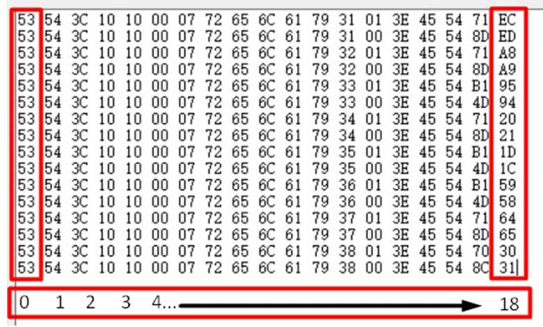
It checks the first byte of the frame (Buffer[0]) to verify if it matches the expected value (0x53) to ensure it’s a valid frame. Depending on the specific values received at index 18 of the frame (Buffer[18]), the code toggles the corresponding relay channels ON or OFF accordingly.
/* Checking first index of the frame as it is 0x53 */
    if (Buffer[0] == 0x53) {
      /* Checking condition for Relay- 1 [ON] at frame index 18 with value 0xEC */
      if (Buffer[18] == 0xEC) {
        Serial.println("Relay1_ON");
        digitalWrite(Relay1, LOW);
      }
      /* Checking condition for Relay- 1 [OFF] at frame index 18 with value 0xED */
      else if (Buffer[18] == 0xED) {
        Serial.println("Relay1_OFF");
        digitalWrite(Relay1, HIGH);
      }
      /* Checking condition for Relay-2 [ON] at frame index 18 with value 0xA8 */
      else if (Buffer[18] == 0xA8) {
        Serial.println("Relay2_ON");
        digitalWrite(Relay2, LOW);
      }
      /* Checking condition for Relay-2 [OFF] at frame index 18 with value 0xA9 */
      else if (Buffer[18] == 0xA9) {
        Serial.println("Relay2_OFF");
        digitalWrite(Relay2, HIGH);
      }
      /* Checking condition for Relay-3 [ON] at frame index 18 with value 0x95 */
      else if (Buffer[18] == 0x95) {
        Serial.println("Relay3_ON");
        digitalWrite(Relay3, LOW);
      }
      /* Checking condition for Relay-3 [OFF] at frame index 18 with value 0x94 */
      else if (Buffer[18] == 0x94) {
        Serial.println("Relay3_OFF");
        digitalWrite(Relay3, HIGH);
      }
      /* Checking condition for Relay-4 [ON] at frame index 18 with value 0x20 */
      else if (Buffer[18] == 0x20) {
        Serial.println("Relay4_ON");
        digitalWrite(Relay4, LOW);
      }
      /* Checking condition for Relay-4 [OFF] at frame index 18 with value 0x21 */
      else if (Buffer[18] == 0x21) {
        Serial.println("Relay4_OFF");
        digitalWrite(Relay4, HIGH);
      }
      /* Checking condition for Relay-5 [ON] at frame index 18 with value 0x1D */
      else if (Buffer[18] == 0x1D) {
        Serial.println("Relay5_ON");
        digitalWrite(Relay5, LOW);
      }
      /* Checking condition for Relay-5 [OFF] at frame index 18 with value 0x1C */
      else if (Buffer[18] == 0x1C) {
        Serial.println("Relay5_OFF");
        digitalWrite(Relay5, HIGH);
      }
      /* Checking condition for Relay-6 [ON] at frame index 18 with value 0x59 */
      else if (Buffer[18] == 0x59) {
        Serial.println("Relay6_ON");
        digitalWrite(Relay6, LOW);
      }
      /* Checking condition for Relay-6 [OFF] at frame index 18 with value 0x58 */
      else if (Buffer[18] == 0x58) {
        Serial.println("Relay6_OFF");
        digitalWrite(Relay6, HIGH);
      }
      /* Checking condition for Relay-7 [ON] at frame index 18 with value 0x64 */
      else if (Buffer[18] == 0x64) {
        Serial.println("Relay7_ON");
        digitalWrite(Relay7, LOW);
      }
      /* Checking condition for Relay-7 [OFF] at frame index 18 with value 0x65 */
      else if (Buffer[18] == 0x65) {
        Serial.println("Relay7_OFF");
        digitalWrite(Relay7, HIGH);
      }
      /* Checking condition for Relay-8 [ON] at frame index 18 with value 0x30 */
      else if (Buffer[18] == 0x30) {
        Serial.println("Relay8_ON");
        digitalWrite(Relay8, LOW);
      }
      /* Checking condition for Relay-8 [OFF] at frame index 18 with value 0x31 */
      else if (Buffer[18] == 0x31) {
        Serial.println("Relay8_OFF");
        digitalWrite(Relay8, HIGH);
      }
    }
The temperature and humidity readings are then read from the DHT11 sensor.
  // Read temperature and humidity from the DHT sensor
  tempr = dht.readTemperature();
  humid = dht.readHumidity();
The code creates a JSON document (jsonDoc) to format the temperature and humidity data to be sent to the Stone HMI Display.
// Update temperature and humidity data on the Stone HMI display
  StaticJsonDocument<100> jsonDoc;
  jsonDoc["cmd_code"] = "set_value";
  jsonDoc["type"] = "label";
  jsonDoc["widget"] = "temp";
The temperature and humidity values are converted to character arrays (tempStr and humidStr) with two decimal places using dtostrf.
// Use dtostrf to convert float values to character arrays with two decimal places
  char tempStr[10];
  char humidStr[10];
  dtostrf(tempr, 4, 2, tempStr); // 4 is the total width, 2 is the decimal places
  dtostrf(humid, 4, 2, humidStr); // 4 is the total width, 2 is the decimal places
The JSON document is populated with the widget information (“temp” and “humi“) and the formatted temperature and humidity values.
  jsonDoc["value"] = atof(tempStr); // Convert back to float for JSON
  jsonDoc["format"] = "%.2f";
The JSON document is serialized and written to the Serial port with the appropriate start (ST<) and end (>ET) markers to indicate the beginning and end of the data frame.
serializeJson(jsonDoc, TxData);
  Serial.write("ST<");
  Serial.write(TxData);
  Serial.write(">ETn");

  jsonDoc.clear();
  jsonDoc["cmd_code"] = "set_value";
  jsonDoc["type"] = "label";
  jsonDoc["widget"] = "humi";
  jsonDoc["value"] = atof(humidStr); // Convert back to float for JSON
  jsonDoc["format"] = "%.2f";

  serializeJson(jsonDoc, TxData);
  Serial.write("ST<");
  Serial.write(TxData);
  Serial.write(">ETn");
The code waits for one second using a delay of 1 second before updating the data again (you can adjust this delay as needed).
delay(1000); // Update the data every 1 second (adjust as needed)
Project Demonstration: Stone HMI Smart Home
With the hardware and software setup complete, let’s explore how this smart home project works:
The Arduino Nano reads temperature and humidity data from the DHT11 sensor.

It also listens for UART commands from the Stone HMI Display through the RS232 to TTL Converter Module. The Stone HMI Display displays the real-time temperature and humidity values on the labels.
When the user interacts with the buttons or switches on the HMI Display, it sends corresponding UART commands to the Arduino.
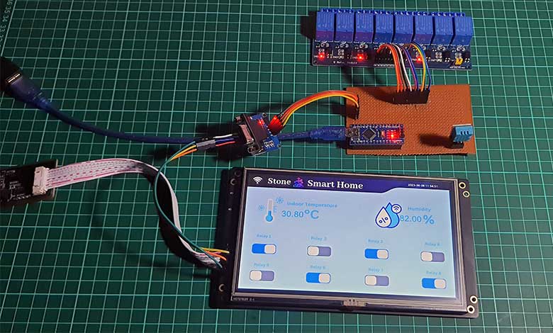
Based on the received commands, the Arduino toggles the relay channels ON or OFF to control the connected devices.
Conclusion
So, that’s how we made a simple smart home project by interfacing a stone HMI touch display with Arduino. I hope you learned a lot and the tutorial was helpful to you. If you have any doubts or queries then do let me know in the comment section below.

