Wind Speed Meter Using Anemometer & Arduino
Measure Wind Speed usign Anemometer & Arduino
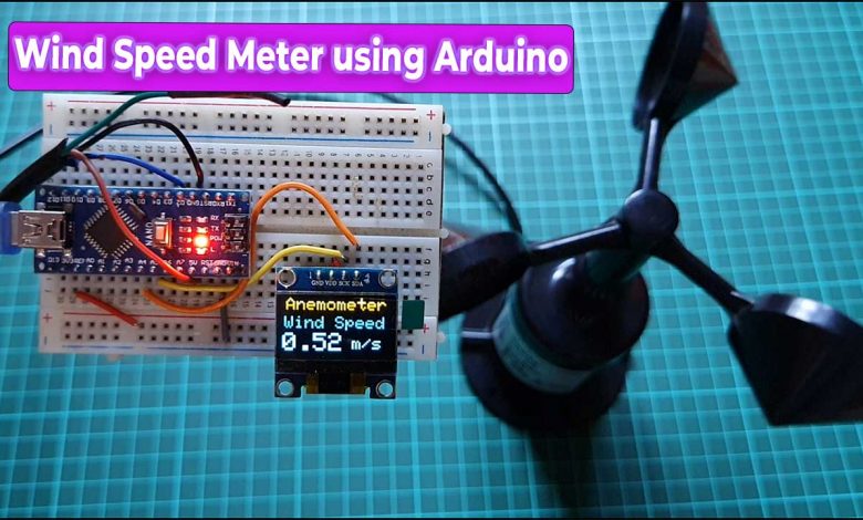
In this tutorial, we will make a wind speed meter using NPN pulse output Anemometer sensor and Arduino. The Anemometer sensor is a device used for measuring wind speed and direction. It is also a common weather station instrument.
Overview: Wind Speed Meter using Anemometer
This is a digital anemometer sensor that has NPN pulse output. The NPN pulse output anemometer result is good and is also cost-effective. The best part is it operates only at 5V supply.
Alright in this project, we will learn how we can interface this anemometer sensor with an Arduino board and 0.96 inch OLED display. The OLED display will display the wind speed in meters per second and can measure wind speed in the range of 0 to 70 meters per second.
Components Required
Following are the components that we need for making Wind Speed Meter Using Anemometer. You can purchase all the components easily from Amazon. Check the purchase link provided below.
| S.N | Components Name | Quantity | |
|---|---|---|---|
| 1 | Arduino Nano | 1 | https://amzn.to/3Hf7zvN |
| 2 | 0.96" I2C OLED Display | 1 | https://amzn.to/3kvENyc |
| 3 | Anemometer Sensor | 1 | https://amzn.to/3qoa88h |
| 4 | Few jumpers wires | 10 | https://amzn.to/3klh0A4 |
What is NPN Pulse Output Anemometer?
The NPN pulse output Anemometer sensor is a 3 cup type Anemometer that is capable of measuring wind speed up to 70-meter per seconds or 156 mph. It is composed of a shell, the wind cup, and the circuit module. After testing many types of anemometers, we found out this NPN pulse output anemometer quality is best as well as cost-effective.
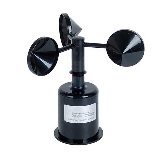
Unlike the analog output version anemometer, this anemometer output pulse reflects the wind speed more accurately. Besides, this anemometer is totally waterproof, with a stable installation design, and suitable for outdoor applications.
Features & Specifications
It operates between 5 volt to 30 volt DC. The output is pulse type with the resolution of 0.0875 meter per seconds. The wind measuring ranges between 0 to 70 meter per seconds.
In working, if the Anemometer turns one round in one second the transmitter will output 20 pulses. which means the wind speed is 1.75 meter per seconds. Similarly in 4.5 rotation the transmitter will output 90 pulses this means the wind speed is 7.87 meter per seconds.
Wiring & Pinout
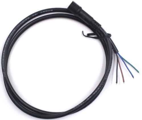
The anemometer sensor has four wires; the brown is the VCC pin which can accept 5 volt to 30 volt input. The Black is the GND pin, Blue is the NPNR output pin, and the Green is the PNP output pin. We won’t use the green wire in this project.
| Wires | Mark | Definition |
| Brown line | VCC | Power supply |
| Black line | GND | Grounding |
| Green line | (PNP)OUTPUT | Pulse output |
| Blue line | (NPNR)OUTPUT | Pulse output |
Interfacing NPN Pulse Output Anemometer with Arduino
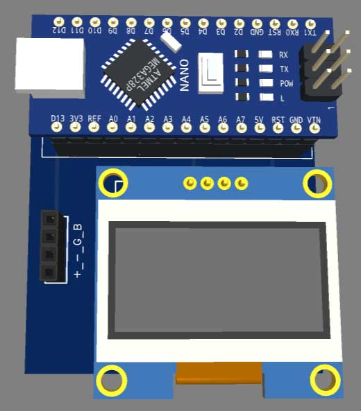
Alright let’s move to the Practical part. This is the Arduino Nano board. We will use this microcontroller in this project to read wind speed and in order to display the wind speed we will use a I2C OLED display. I2C will help in reducing the number of wires.
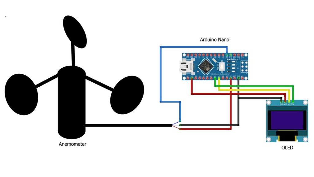
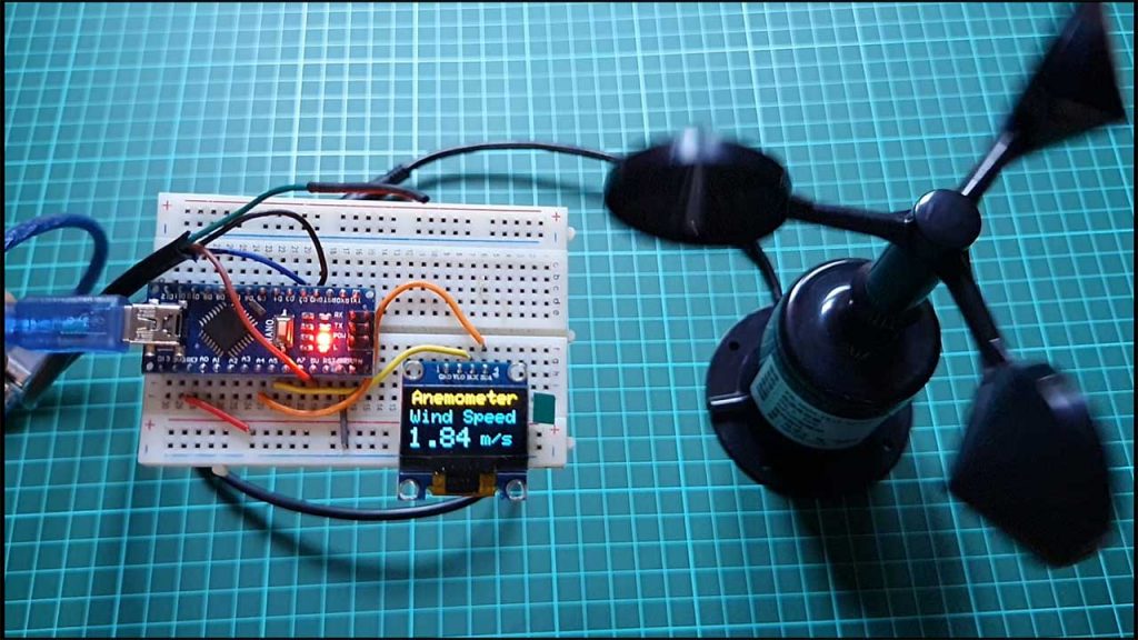
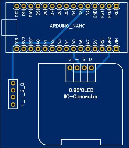
This is the circuit diagram for this project. The LCD and both anemometer sensors are powered through a 5 volt pin of Arduino. The output pin of the anemometer is connected to the D2 pin of Arduino. Similarly the LCD is connected to the I2C pins of Arduino. I used a breadboard to assemble the circuit.
The Arduino board, OLED display unit and the anemometer sensor all of them are connected to each other as per the circuit diagram. I powered the Arduino board using the USB power from the power bank. You may use any 5V DC adapter.
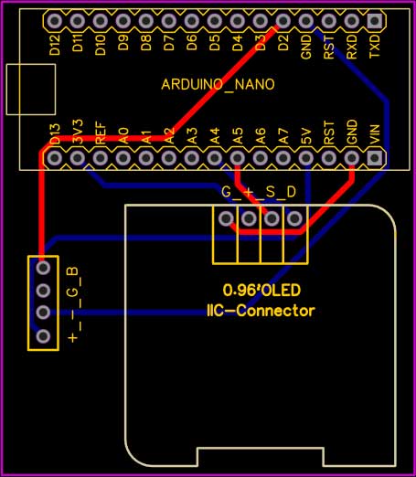
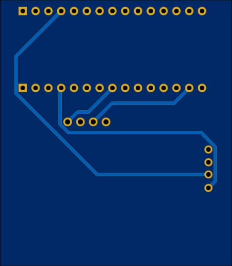
Ordering Custom PCB Online
Do you want professional PCBs like this one that look so good then use the services of PCBWay.com
Because PCBWay is a one-stop solution for all your PCB needs like PCB prototyping, SMD stencils, PCB assembly, 3D printing, etc.

So, get your prototype PCB ready from pcbway.com, the Gerber file link is provided below.
- Just click on the PCB Instant quote tab.
- Then click on Quick Order PCB.
- Now Upload your Gerber file
- Select your preferred shipping method
- Place your order.
Source Code/Program
Here is the source code for Wind Speed Meter Using Anemometer & Arduino. You can copy the below code into your Arduino IDE.
#include <Adafruit_GFX.h>
#include <Adafruit_SSD1306.h>

#define SCREEN_WIDTH 128 // OLED display width, in pixels
#define SCREEN_HEIGHT 64 // OLED display height, in pixels
// Declaration for an SSD1306 display connected to I2C (SDA, SCL pins)
#define OLED_RESET     -1 // Reset pin # (or -1 if sharing Arduino reset pin)
Adafruit_SSD1306 display(SCREEN_WIDTH, SCREEN_HEIGHT, &Wire, OLED_RESET);

unsigned long lastDebounceTime = 0;  // the last time the output pin was toggled
unsigned long debounceDelay = 1000;    // the debounce time; increase if the output flickers

int pinInterrupt = 2;

int Count = 0;

void onChange()
{
  if ( digitalRead(pinInterrupt) == LOW )
    Count++;
}


void setup()
{
  Serial.begin(115200); //Initialize serial port
  pinMode( pinInterrupt, INPUT_PULLUP);// set the interrupt pin

  //Enable
  attachInterrupt( digitalPinToInterrupt(pinInterrupt), onChange, FALLING);

  display.begin(SSD1306_SWITCHCAPVCC, 0x3C);
  delay(500);
  display.clearDisplay();
  display.setTextColor(WHITE);

}

void loop()
{
  if ((millis() - lastDebounceTime) > debounceDelay)
  {
    lastDebounceTime = millis();

    Serial.print((Count * 8.75)/100);

       //clear display
    display.clearDisplay();

    display.setTextSize(2);
    display.setCursor(4, 0);
    display.print("Anemometer");

    display.setCursor(2, 20); //oled display
    display.setTextSize(2);
    display.println("Wind Speed");

    display.setCursor(0, 40); //oled display
    display.setTextSize(3);
    display.print((Count * 8.75)/100);
    display.setCursor(70, 45);
    display.setTextSize(2);
    display.println(" m/s");
    display.display();

    Count = 0;

    Serial.println("m/s");

  }
  delay(1);
}
Source/Program Code Explanation
First we need an OLED display library. For that you need to install Adafruit GFX and Adafruit SSD1306 library from the library manager.
#include <Adafruit_GFX.h>
#include <Adafruit_SSD1306.h>
Then we defined OLED width, height, I2C pins, and reset pin to initialize the OLED display.
#define SCREEN_WIDTH 128 // OLED display width, in pixels
#define SCREEN_HEIGHT 64 // OLED display height, in pixels
// Declaration for an SSD1306 display connected to I2C (SDA, SCL pins)
#define OLED_RESET     -1 // Reset pin # (or -1 if sharing Arduino reset pin)
Adafruit_SSD1306 display(SCREEN_WIDTH, SCREEN_HEIGHT, &Wire, OLED_RESET);
Then we Define some variables for time calculation.
unsigned long lastDebounceTime = 0;  // the last time the output pin was toggled
unsigned long debounceDelay = 1000;    // the debounce time; increase if the output flickers
The interrupt pin is defined as digital pin 2 of the Arduino which we have connected earlier.
Here we initialize the count at zero.
int pinInterrupt = 2; // D2 pin of Arduino
Under the onChange function we are calculating the pulse based on Interrupt.
void onChange()
{
  if ( digitalRead(pinInterrupt) == LOW )
    Count++;
}
In the setup section, we initialized serial begin then pin mode is an interrupt pin. then we enable the interrupt.
  Serial.begin(115200); //Initialize serial port
  pinMode( pinInterrupt, INPUT_PULLUP);// set the interrupt pin

  //Enable
  attachInterrupt( digitalPinToInterrupt(pinInterrupt), onChange, FALLING);
This will initialize OLED and its operations.
  display.begin(SSD1306_SWITCHCAPVCC, 0x3C);
  delay(500);
  display.clearDisplay();
  display.setTextColor(WHITE);
In the loop section we are calculating the wind speed on the basis of pulse output. First the wind speed is displayed on the serial monitor then we display the wind speed on our 0.96 inch OLED display.
 if ((millis() - lastDebounceTime) > debounceDelay)
  {
    lastDebounceTime = millis();

    Serial.print((Count * 8.75)/100);

       //clear display
    display.clearDisplay();

    display.setTextSize(2);
    display.setCursor(4, 0);
    display.print("Anemometer");

    display.setCursor(2, 20); //oled display
    display.setTextSize(2);
    display.println("Wind Speed");

    display.setCursor(0, 40); //oled display
    display.setTextSize(3);
    display.print((Count * 8.75)/100);
    display.setCursor(70, 45);
    display.setTextSize(2);
    display.println(" m/s");
    display.display();

    Count = 0;

    Serial.println("m/s");

  }
Now from the tools menu select Arduino Nano board then select the COM Port. Now you can upload the code.
Measuring Wind Speed & Testing the Device
After uploading the code and powering up the entire device, the LCD will display the wind speed 0.00 meter per second.
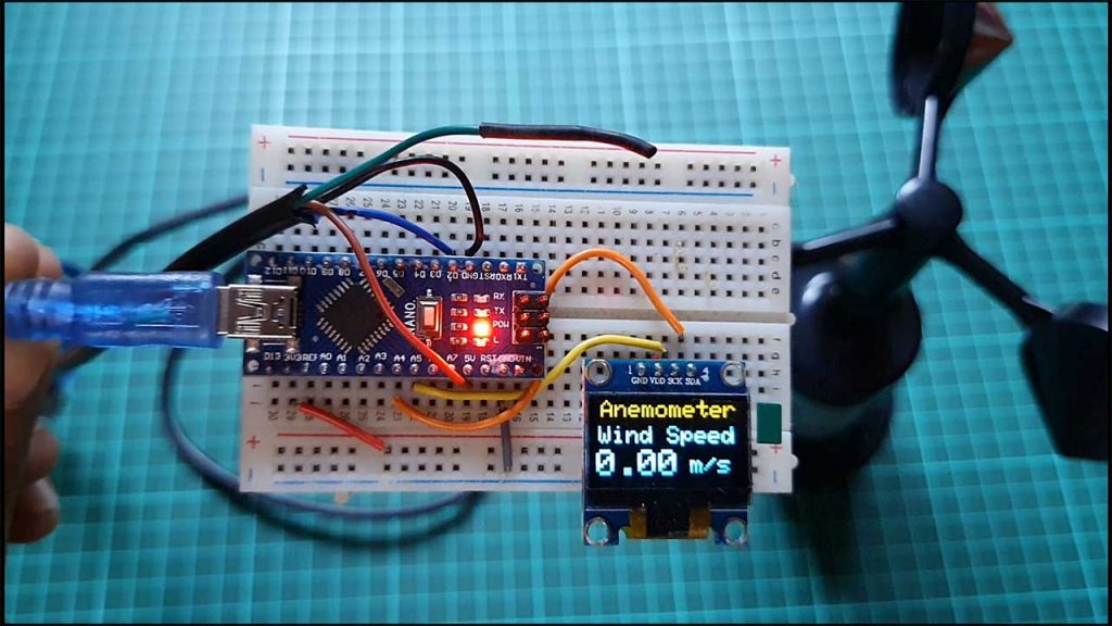
This is because the cups are not moving and there is no rotation. The wind speed will change as the cup of the anemometer starts moving. I am currently testing indoors therefore I’m rotating it using my hand. As the cop spins faster the more is the wind speed.
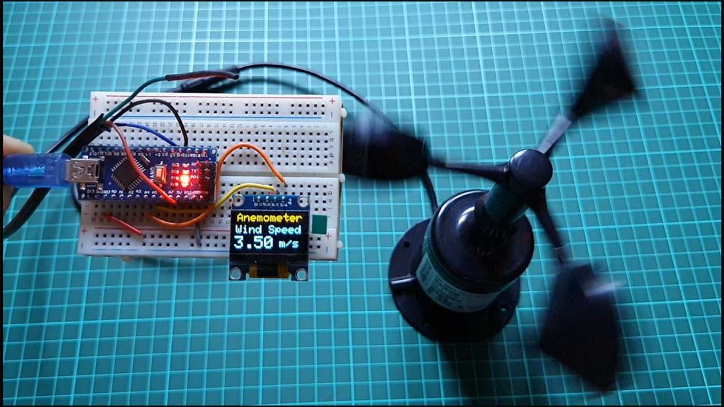
I am measuring the speed as a meter per second but you can change the unit to miles per hour.
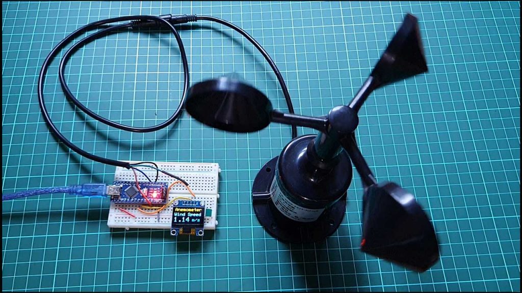
Now, I placed the entire unit on the roof of my house and currently the Cups are moving. The wind speed shown here is between 0 to 2 meters per second. You can fix this anemometer during windy days.
Conclusion
Alright that’s all for today’s project. The complete project details including device information purchase link source code and written tutorial is provided to you. In case you have any other questions you can comment in the comment section below thank you so much for visiting.


Why do I need to buy an anemometer if I can 3D print it myself?
IMHO a Hall sensor and a small neodymium magnet can also do the job or am I missing something 🤔
3D print it and install it under one year of 15 UV and rain and let’s see after.