Arduino based Decibel meter with Sound Sensor
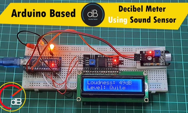
In this project, we will make Arduino based Decibel meter with Sound Sensor & monitor sound level on LCD Display.
Overview: Arduino Decibel Meter using Sound Sensor
You might have seen the decibel meter available in the market that generally measures the sound intensity and level. The sound loudness is measured in terms of decibel. Different sound-producing medium ranging from airplanes to human whisper has a certain level of sound loudness expressed in decibel. Sound waves are the longitudinal waves that have To and Fro motion giving high or low pitch as shown in the image.

The loudness of a sound depends upon the frequency or wavelength or the time required for propagation. Below is the table that shows the level of sound in dB from the threshold of hearing to whisper sound to the bus station or jet planes.
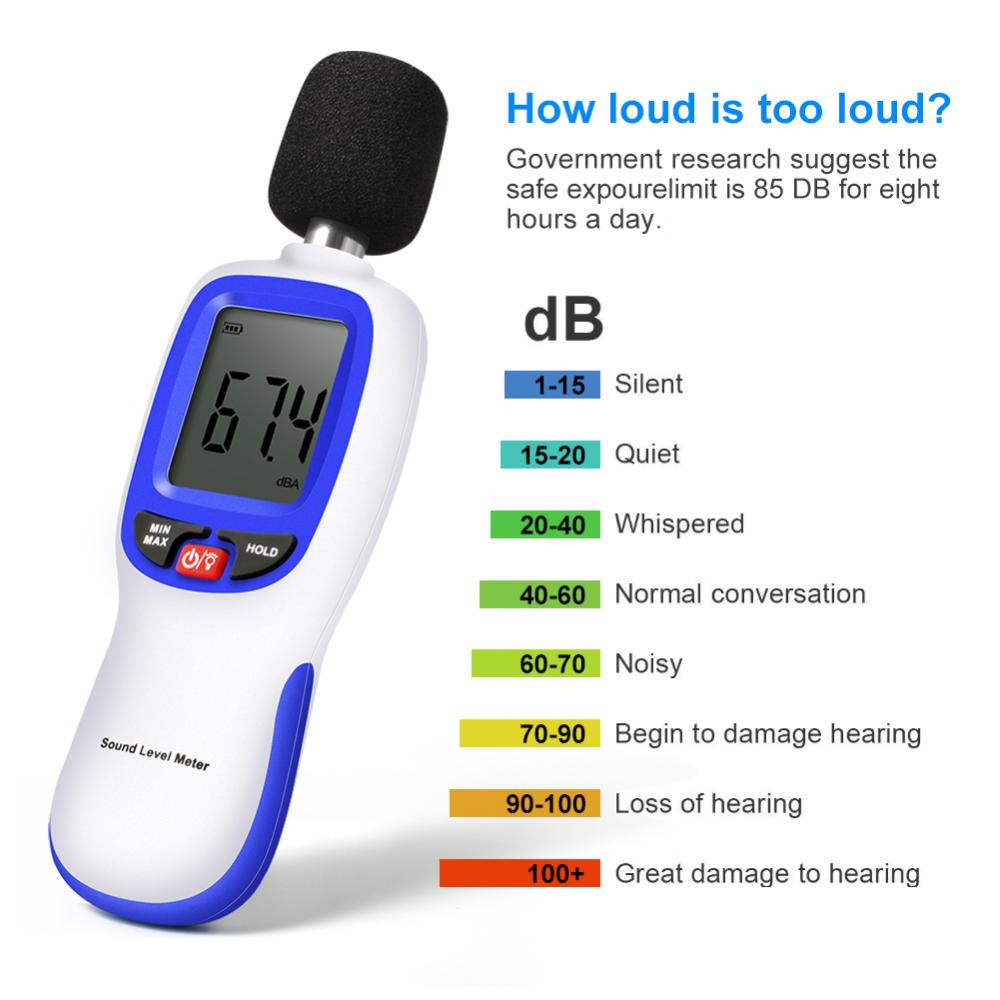
But unfortunately, all the sound level meters available in the market are expensive. that is why I decided to make an Arduino-based decibel meter. Using this sound level meter I can monitor the sound level and intensity on LCD Screen. So I used Arduino Nano along with the sound sensor module with a 16×2 I2C LCD Display.
The sound sensor generally, reads the analog value of sound which is then converted into the decibel using some mathematical formula.
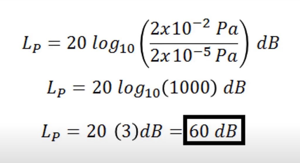
So in this tutorial, we will use the sound module. This sound module has a mic and an amplifier circuit which is read by a microcontroller.
Before starting, you can check the previous post to get started with LCD Display:
1. IoT based Decibel Meter with ESP8266 & Sound Sensor
2. IoT Smart Agriculture Monitoring & Automatic Irrigation System using ESP8266
Components Required
Now in this tutorial, we’re using Arduino NANO, 16×2 I2C LCD, 3 different color LEDs, and some jumper cables. Here, we are using a breadboard for the assembly. So these are the hardware components required for making this project. All the components can be easily purchased from Amazon. The components purchase link is given below.
| S.N | Components Name | Quantity | |
|---|---|---|---|
| 1 | Arduino Nano | 1 | https://amzn.to/3Hf7zvN |
| 2 | LM393 Sound Sensor Module | 1 | https://amzn.to/3etAakz |
| 3 | 16X2 I2C LCD Display | 1 | https://amzn.to/3ezvzxa |
| 4 | Multi Color LED | 3 | https://amzn.to/3ezvOIA |
| 5 | Few jumpers wires | 10 | https://amzn.to/3klh0A4 |
| 6 | Breadboard | 1 | https://amzn.to/3H2tbeQ |
Microphone Sound Sensor
This is a sound sensor module that I order recently to make a decibel meter. It has a perfect condenser mic that detects the level of sound from the sound-producing medium. The sound sensor is a small board that combines a microphone (50Hz-10kHz) and some circuit connections to convert sound waves into electrical pulses. This electrical pulse is fed to the LM393 which is a comparator IC. LM393 IC helps to digitize the signal and is available at the OUT pin.
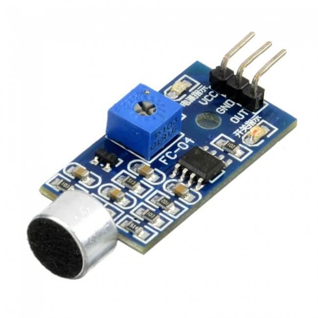
This Sound sensor has a potentiometer that is used to adjust the Sensitivity of the OUT signal. It has 3 pins that are OUT, VCC and GND.
Decibel meter with Arduino & 16×2 I2C LCD Display
So here is the circuit diagram we have assembled on the breadboard.
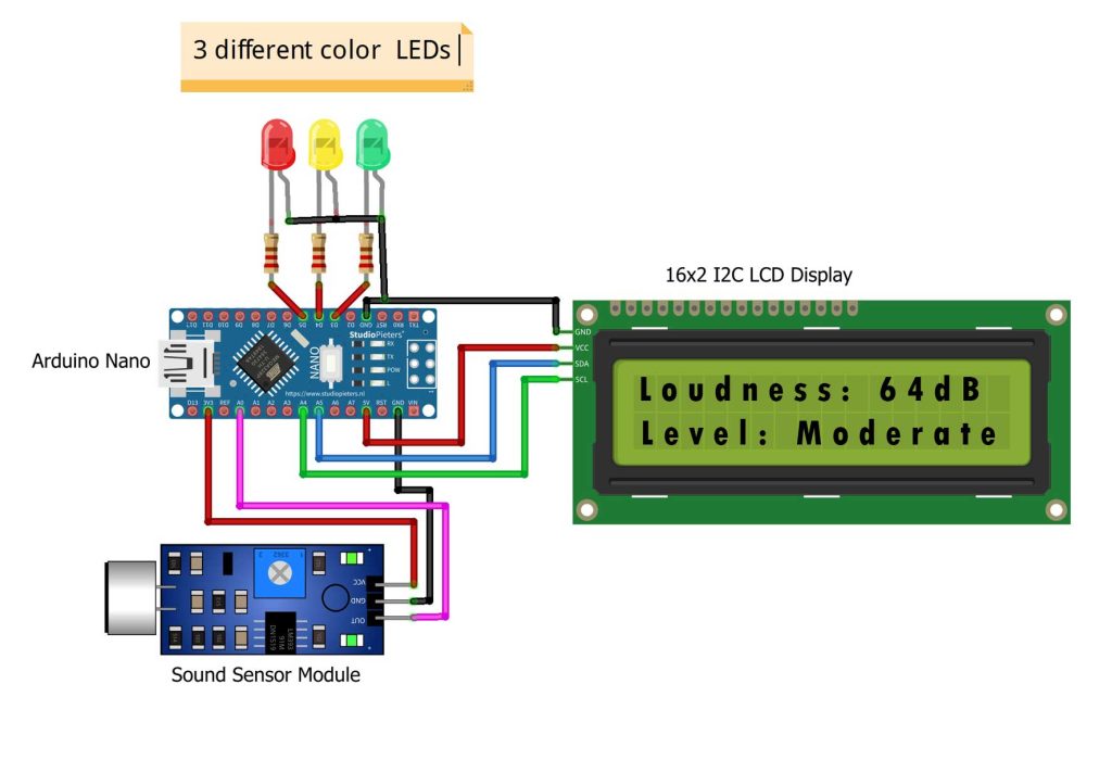
Connect the I2C Pins (SDA, SCL) of LCD Display to A5 & A4 pin of Arduino. Supply the LCD Display with 5V through 5V Pin. Similarly, supply the Sound Sensor with a 3.3V supply through 3.3V Pin. You can also add 3 LEDs of a different color to Arduino D3, D4 & D5 Pins. This LED glows based on different sound intensities. The sound sensor interfaced with the analog pin A0. Here Analog pin is connected because the sound sensor is analog.
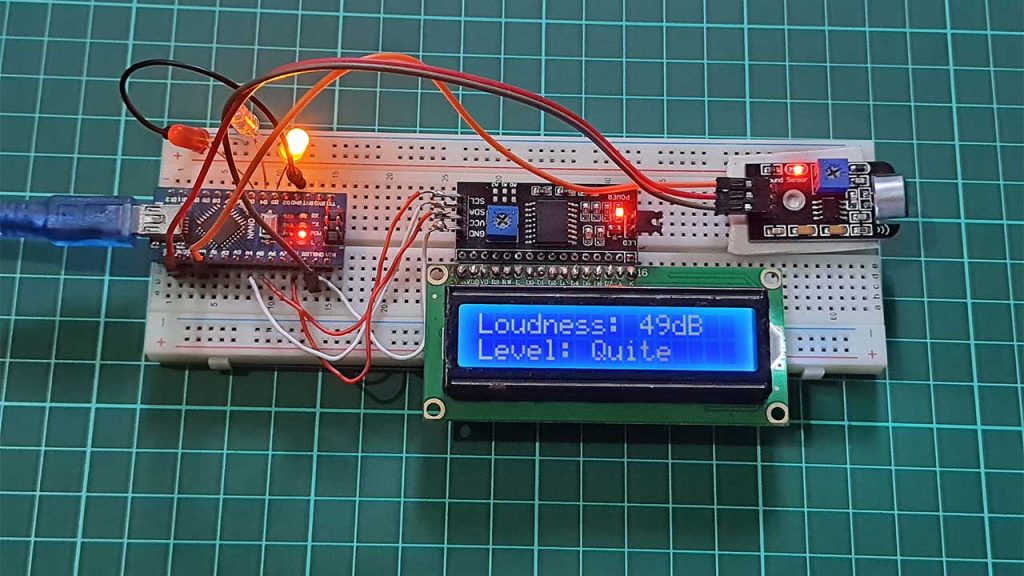
So here is the assembly on a breadboard. All the components are assembled as per the circuit diagram.
PCB Designing & Ordering
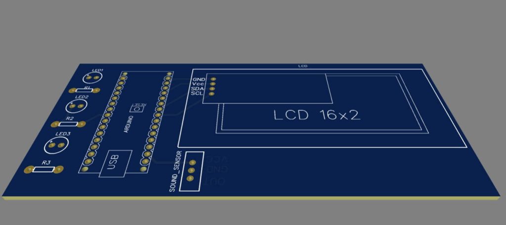
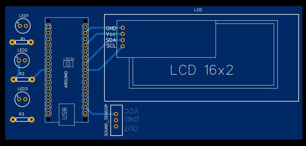
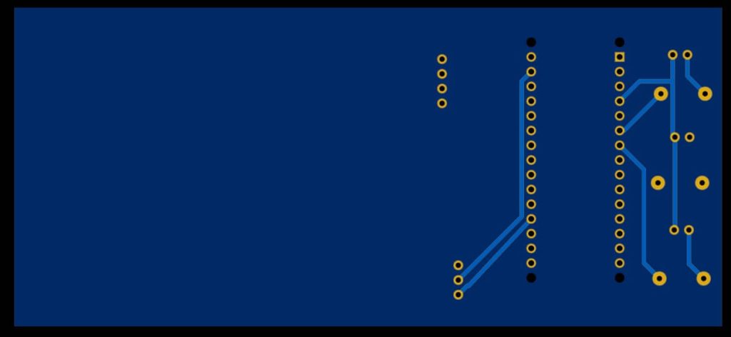
You can simply assemble the circuit on a breadboard. But if you don’t want to assemble the circuit on a breadboard, you can follow this schematic and build your own PCB. You can download the Gerber file of my PCB Design from the link attached below. The PCB looks like the image shown below.
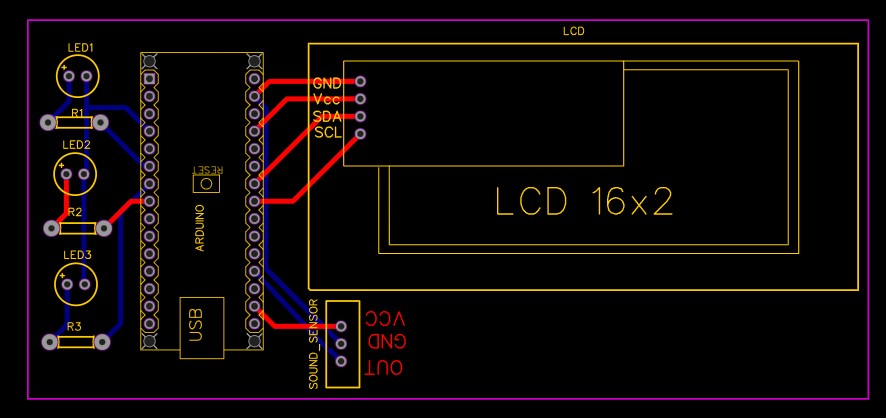
I provided the Gerber File for the Arduino-based Decibel meter with Sound Sensor PCB below.
You can simply download the Gerber File and order your custom PCB from PCBWay

Visit the PCBWay official website by clicking here: https://www.PCBWay.com/. Simply upload your Gerber File to the Website and place an order. The reason behind most of the people trusting PCBWay for PCB & PCBA Services is because of their quality. The PCB quality is superb and has a very high finish, as expected.
Source Code: Decibel meter with Arduino & LCD Display
This is the simple code that I have written in Arduino IDE. So you need to add the I2C LCD library and you need to define the A0 pin of the Arduino that we are using to detect the sound.
#include <Wire.h>
#include <LiquidCrystal_I2C.h> // Library for LCD
LiquidCrystal_I2C lcd = LiquidCrystal_I2C(0x27, 16, 2);

const int sampleWindow = 50;                              // Sample window width in mS (50 mS = 20Hz)
unsigned int sample;

#define SENSOR_PIN A0
#define PIN_QUIET 3
#define PIN_MODERATE 4
#define PIN_LOUD 5
Using this formula we are converting the minimum and maximum voltage generated into a decibel value.
unsigned long startMillis= millis();                   // Start of sample window
   float peakToPeak = 0;                                  // peak-to-peak level

   unsigned int signalMax = 0;                            //minimum value
   unsigned int signalMin = 1024;                         //maximum value

                                                          // collect data for 50 mS
   while (millis() - startMillis < sampleWindow)
   {
      sample = analogRead(SENSOR_PIN);                    //get reading from microphone
      if (sample < 1024)                                  // toss out spurious readings
      {
         if (sample > signalMax)
         {
            signalMax = sample;                           // save just the max levels
         }
         else if (sample < signalMin)
         {
            signalMin = sample;                           // save just the min levels
         }
      }
   }

   peakToPeak = signalMax - signalMin;                    // max - min = peak-peak amplitude
   int db = map(peakToPeak,20,900,49.5,90);             //calibrate for deciBels
Similarly, using this function we are displaying the sound intensity in dB using LCD and also providing (Normal, Moderate, and Extreme noise) signal through different color led.
if (db <= 60)
  {
    lcd.setCursor(0, 1);
    lcd.print("Level: Quite");
    digitalWrite(PIN_QUIET, HIGH);
    digitalWrite(PIN_MODERATE, LOW);
    digitalWrite(PIN_LOUD, LOW);
  }
  else if (db > 60 && db<85)
  {
    lcd.setCursor(0, 1);
    lcd.print("Level: Moderate");
    digitalWrite(PIN_QUIET, LOW);
    digitalWrite(PIN_MODERATE, HIGH);
    digitalWrite(PIN_LOUD, LOW);
  }
  else if (db>=85)
  {
    lcd.setCursor(0, 1);
    lcd.print("Level: High");
    digitalWrite(PIN_QUIET, LOW);
    digitalWrite(PIN_MODERATE, LOW);
    digitalWrite(PIN_LOUD, HIGH);

  }
Check this complete source code below.
#include <Wire.h>
#include <LiquidCrystal_I2C.h> // Library for LCD
LiquidCrystal_I2C lcd = LiquidCrystal_I2C(0x27, 16, 2);

const int sampleWindow = 50;                              // Sample window width in mS (50 mS = 20Hz)
unsigned int sample;

#define SENSOR_PIN A0
#define PIN_QUIET 3
#define PIN_MODERATE 4
#define PIN_LOUD 5

void setup ()
{
  pinMode (SENSOR_PIN, INPUT); // Set the signal pin as input
  pinMode(PIN_QUIET, OUTPUT);
  pinMode(PIN_MODERATE, OUTPUT);
  pinMode(PIN_LOUD, OUTPUT);

  digitalWrite(PIN_QUIET, LOW);
  digitalWrite(PIN_MODERATE, LOW);
  digitalWrite(PIN_LOUD, LOW);

  Serial.begin(115200);
  lcd.begin();

  // Turn on the backlight.
  lcd.backlight();
    lcd.clear();
}


void loop ()
{
   unsigned long startMillis= millis();                   // Start of sample window
   float peakToPeak = 0;                                  // peak-to-peak level

   unsigned int signalMax = 0;                            //minimum value
   unsigned int signalMin = 1024;                         //maximum value

                                                          // collect data for 50 mS
   while (millis() - startMillis < sampleWindow)
   {
      sample = analogRead(SENSOR_PIN);                    //get reading from microphone
      if (sample < 1024)                                  // toss out spurious readings
      {
         if (sample > signalMax)
         {
            signalMax = sample;                           // save just the max levels
         }
         else if (sample < signalMin)
         {
            signalMin = sample;                           // save just the min levels
         }
      }
   }

   peakToPeak = signalMax - signalMin;                    // max - min = peak-peak amplitude
   int db = map(peakToPeak,20,900,49.5,90);             //calibrate for deciBels

  lcd.setCursor(0, 0);
  lcd.print("Loudness: ");
  lcd.print(db);
  lcd.print("dB");

  if (db <= 60)
  {
    lcd.setCursor(0, 1);
    lcd.print("Level: Quite");
    digitalWrite(PIN_QUIET, HIGH);
    digitalWrite(PIN_MODERATE, LOW);
    digitalWrite(PIN_LOUD, LOW);
  }
  else if (db > 60 && db<85)
  {
    lcd.setCursor(0, 1);
    lcd.print("Level: Moderate");
    digitalWrite(PIN_QUIET, LOW);
    digitalWrite(PIN_MODERATE, HIGH);
    digitalWrite(PIN_LOUD, LOW);
  }
  else if (db>=85)
  {
    lcd.setCursor(0, 1);
    lcd.print("Level: High");
    digitalWrite(PIN_QUIET, LOW);
    digitalWrite(PIN_MODERATE, LOW);
    digitalWrite(PIN_LOUD, HIGH);

  }

   delay(200);
   lcd.clear();
}
Now select the correct board and correct port from the Tools menu and then upload the code. once you upload the code sensor get ready and you can measure the sound level intensity on the LCD display.
Monitor Sound dB on LCD Display using Arduino
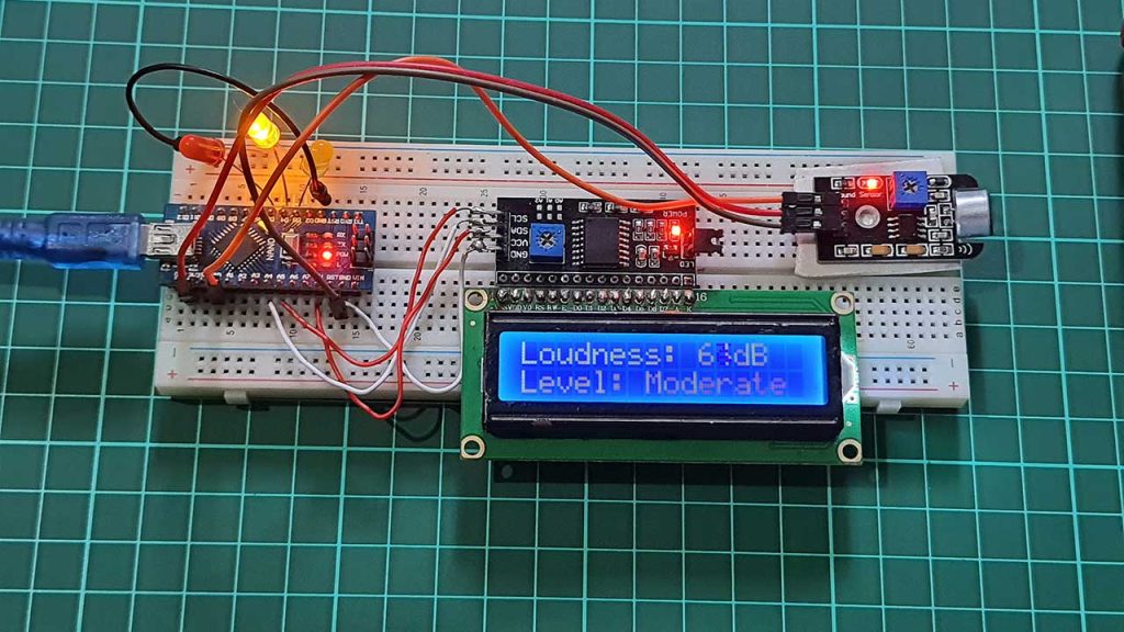
After the code is uploaded to the Arduino Nano board. All the processes can be observed in the 16×2 LCD display. Now you can play music and observe the value on LCD Display.
Video Tutorial & Guide
So, this is how we made Arduino based Decibel meter with Sound Sensor and 16×2 LCD Display. This DIY project is very helpful for monitoring sound levels in dB. If you have any doubts and queries then do let us know in the comment section. The video tutorial of this project is embedded below.

Arduino: 1.8.14 (Windows 10), Board: “Arduino NANO 33 IoT”
meter:3:54: error: invalid conversion from ‘int’ to ‘t_backlightPol’ [-fpermissive]
LiquidCrystal_I2C lcd = LiquidCrystal_I2C(0x27, 16, 2);
^
In file included from C:\Users\cza89\Documents\Arduino\meter\meter.ino:2:0:
C:\Users\cza89\Documents\Arduino\libraries\New-LiquidCrystal-master/LiquidCrystal_I2C.h:65:4: note: initializing argument 3 of ‘LiquidCrystal_I2C::LiquidCrystal_I2C(uint8_t, uint8_t, t_backlightPol)’
LiquidCrystal_I2C (uint8_t lcd_Addr, uint8_t backlighPin, t_backlightPol pol);
^~~~~~~~~~~~~~~~~
C:\Users\cza89\Documents\Arduino\meter\meter.ino: In function ‘void setup()’:
meter:25:13: error: no matching function for call to ‘LiquidCrystal_I2C::begin()’
lcd.begin();
^
In file included from C:\Users\cza89\Documents\Arduino\meter\meter.ino:2:0:
C:\Users\cza89\Documents\Arduino\libraries\New-LiquidCrystal-master/LiquidCrystal_I2C.h:122:17: note: candidate: virtual void LiquidCrystal_I2C::begin(uint8_t, uint8_t, uint8_t)
virtual void begin(uint8_t cols, uint8_t rows, uint8_t charsize = LCD_5x8DOTS);
^~~~~
C:\Users\cza89\Documents\Arduino\libraries\New-LiquidCrystal-master/LiquidCrystal_I2C.h:122:17: note: candidate expects 3 arguments, 0 provided
Multiple libraries were found for “LiquidCrystal_I2C.h”
Used: C:\Users\cza89\Documents\Arduino\libraries\New-LiquidCrystal-master
Not used: C:\Users\cza89\Documents\Arduino\libraries\LiquidCrystal_I2C
Not used: C:\Users\cza89\Documents\Arduino\libraries\LiquidCrystal_I2C-master
exit status 1
invalid conversion from ‘int’ to ‘t_backlightPol’ [-fpermissive]
Exception in thread “Thread-16” java.util.ConcurrentModificationException
at java.util.LinkedList$ListItr.checkForComodification(LinkedList.java:966)
at java.util.LinkedList$ListItr.next(LinkedList.java:888)
at processing.app.packages.LibraryList.getByName(LibraryList.java:61)
at cc.arduino.contributions.libraries.LibrariesIndexer.addToInstalledLibraries(LibrariesIndexer.java:132)
at cc.arduino.contributions.libraries.LibrariesIndexer.scanLibrary(LibrariesIndexer.java:231)
at cc.arduino.contributions.libraries.LibrariesIndexer.scanInstalledLibraries(LibrariesIndexer.java:203)
at cc.arduino.contributions.libraries.LibrariesIndexer.rescanLibraries(LibrariesIndexer.java:163)
at processing.app.BaseNoGui.onBoardOrPortChange(BaseNoGui.java:681)
at processing.app.Base.onBoardOrPortChange(Base.java:1345)
at processing.app.Editor$UploadHandler.run(Editor.java:2091)
at java.lang.Thread.run(Thread.java:748)
This report would have more information with
“Show verbose output during compilation”
option enabled in File -> Preferences.
It shows only 49 db. Can you please tell me the solution?
I am having the same problem. Have you solved it?
The problem is two fold:
1) The Sound Sensor is selected is NOT the proper one. This code is for the: “DFROBOT Gravity: Analog Sound Sensor”
Which can be found here: https://www.amazon.com/dp/B00B8869R6?psc=1&ref=ppx_yo2ov_dt_b_product_details.
I used it the DFRobot Sound Sensor, it WORKED PERFECT!
2) The second issue is: int db = map(peakToPeak,20,900,49.5,90); wont work for this sensor. The map statement Re-maps a number range to another. The first set of numbers (in this case 20, 900) is what is read from the Analog pin of the sound sensor (A0 in this case) then it takes the second set of numbers (49.5, 90) as the decibel range and the function maps it proportionately.
3) The author didn’t post what library to use for the LCD. So I gave up & used the standard wiring for all 16 pins, & used the built-in LiquidCrystal.h (that came with the IDE. The whole thing works perfect after that)
If anyone knows what library to use, PLEASE POST. I need more data lines ! LOL.
hello i am using the same DFRobot Sound Sensor but the map value is not working can i know what range you are using for the map function
Check your highest and lowest value from the serial monitor then replace this value with yours
This is great info but I am having a hard time figuring out the correct wiring for my Arduino Uno.
My sound sensor is the KY-037.
My LCD is I2C 1602.
Any pointers will be greatly appreciated as I am basically brand new to this and just starting to learn. I’ve been tinkering for 2 weeks and haven’t made progress so thought it is time to reach out.
thanks all!
I also have your sensor and display. you solved? can anyone help us?
A remark regarding the code: assume a loud sound, with analogRead always returning 1023. Then peakToPeak will be zero, which will be interpreted as silence. The code detects large dynamic range within a time window, not loudness. I would only consider signalMax (after calibrating the sensor range).
Im getting the same result only 49db any one to help me
help please
I would like to build this but with the option to trigger some signal to turn on an amplifier with a speaker. My intention is to create a sound masking for the loud music from my Neighbour so when he plays music above the permitted law level the Arduino level sensor will trigger sound of rain or whatever to replace his noise. If he lowers the volume the sensor will turn off.
Could you please share the code for lcd Library
Hello from France !
Your project is very interesting !
I have inclued LiquidCrystal_I2C.h, i tried it for others application. It’s OK.
BUT, I have a message on your code:
On line 25: lcd begin ();
When I tried to make a compilation:
Compilation error: no matching function for call to ‘LiquidCrystal_I2C::begin()’
Could you help me
Thank’s