IoT Temperature Control System with ESP8266 & Blynk
Smart Thermostat Controller With ESP8266 & Blynk IoT
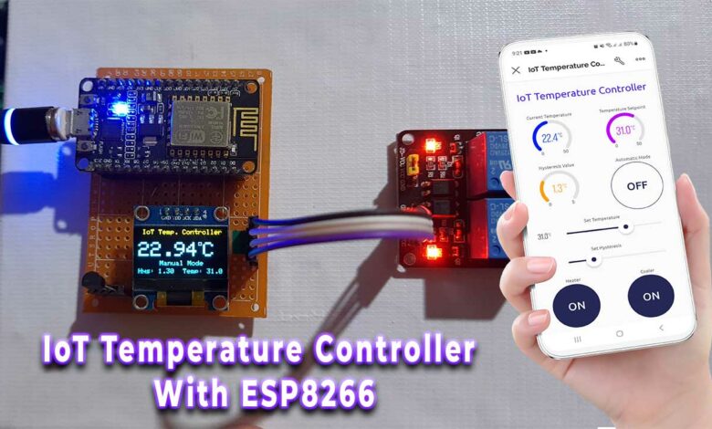
Are you tired of manually adjusting your home thermostat to maintain a comfortable temperature? With this DIY project, you can build your own Internet of Things (IoT) temperature control system using the ESP8266 microcontroller, the DS18B20 temperature sensor, and the Blynk app.
- Overview: IoT Temperature Control System
- Components Required
- Circuit Diagram
- Project PCB Gerber File & PCB Ordering Online
- Setting up Blynk IoT Web Dashboard
- Code/Program: IoT Temperature controller with ESP8266 & Blynk 2.0
- Blynk IoT 2.0 Mobile App Setup
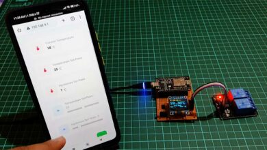
- Testing: IoT Temperature Control System with ESP8266 & Blynk
- Conclusion
Overview: IoT Temperature Control System
We previously built a temperature controller with ESP8266 Webserver. Many of you liked it but it lacks some features like controlling over the internet (should be on the same wifi network to control the device remotely). It cannot store the state of the system in EEPROM so the system cannot retain its settings when there is a power failure.
So, this project is upgraded with many useful features like: monitoring and controlling your system remotely from anywhere in the world using Blynk IoT. Storing the state of the system (heating and cooling relay states, setpoint, hysteresis, and mode) in the EEPROM of the ESP8266, allowing the system to retain its settings even when the power is turned off. You can only turn ON and OFF Heater and Cooler manually when the automatic mode is OFF. You can also see real-time feedback on both Mobile and Web dashboards.
With this project, you’ll be able to set a temperature set point and a hysteresis value to maintain a consistent temperature within a certain range. You can also switch between automatic and manual modes, allowing you to control the heating and cooling relays directly using the Blynk app.
Overall, this is a fun and rewarding project that will allow you to take control of your home’s temperature and save energy in the process. So why wait? Gather your materials, follow the instructions, and start building your own IoT temperature control system today!
Components Required
To build the iot temperature control system with ESP8266, you’ll need the following components:
| S.N | Components Name | Quantity | |
|---|---|---|---|
| 1 | NodeMCU ESP8266 | 1 | https://amzn.to/3WaECc2 |
| 2 | DS18B20 Temperature Sensor | 1 | https://amzn.to/3WLCJm5 |
| 3 | 0.96" I2C OLED Display | 1 | https://amzn.to/3EV50PS |
| 4 | 5V 2-Channel Relay | 1 | https://amzn.to/3C6v363 |
| 5 | Jumper Cables | 10 | https://amzn.to/3YU0c6t |
| 6 | Zero PCB board | 1 | https://amzn.to/3UmLt0B |
Now that we have all of the materials that we need, let’s start by setting up the hardware.
Circuit Diagram
This is the circuit diagram of iot based temperature control system with an ESP8266, DS18B20 sensor, 0.96-inch OLED display, and relays.
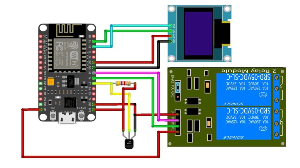
First, connect the OLED display to the ESP8266 using I2C (SCL & SDA) pins. Next, connect the DS18B20 Dallas temperature sensor to the ESP8266 D7 pin. Add a 4.7k ohm resistor between DQ and VDD pin.
Then, connect the two-channel relay to the ESP8266 D5 and D6 pins. While VCC is connected to the Vin pin for a 5V power supply. Connect all GND pins to GND and VCC or VDD pins to the 3.3V pin of the ESP8266 Module. Now we have set up our hardware. Let’s move on to setting up the blynk iot dashboard.
Project PCB Gerber File & PCB Ordering Online
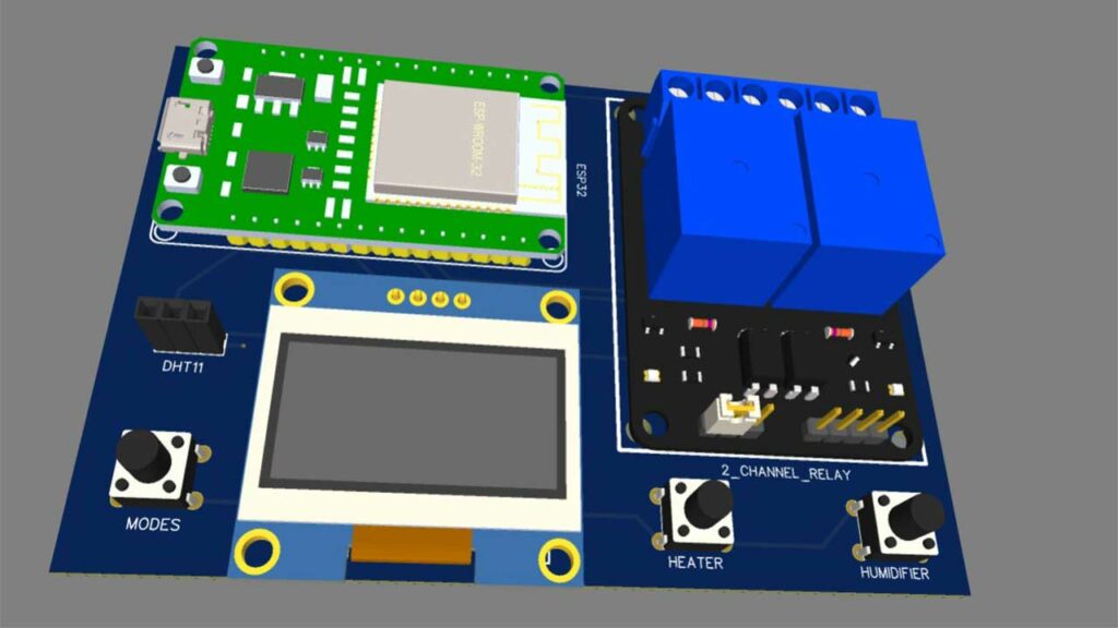
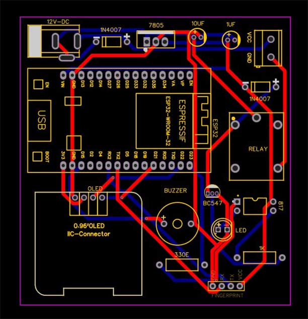
If you don’t want to assemble the circuit on a zero PCB and you want PCB for the project, then here is the PCB for you. The PCB Board for this project looks something like below.
The Gerber File for the PCB is given below. You can simply download the Gerber File and order the PCB from PCBWay.com.
PCBWay Christmas Big Sales is going on, please visit the link provided to get extra discounts and offers.
https://www.pcbway.com/activity/christmas2023.html
Now you can visit the PCBWay official website by clicking here: PCBWay.com. So you will be directed to the PCBWay website.

You can now upload the Gerber File to the Website and place an order. The PCB quality is superb & high standard. That is why most people trust PCBWay for PCB & PCBA Services.
Now, you can assemble the components on the PCB Board.
Setting up Blynk IoT Web Dashboard
In order to monitor and control your temperature controller from Blynk IoT Server. you first need to set up the Blynk IoT Cloud dashboard. To set up the Blynk Server, visit https://blynk.cloud Create an account or simply sign in if you created the account earlier.
Creating Blynk New template
Here we need to create a New Template.
- Enter a template name. I am giving it an “IoT Temperature Controller”.
- Select the hardware board (ESP8266).
- The connection type will be wifi.
- You can add a description of your project if required.
- Click on Done.
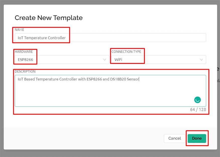
Now the template is created.
Creating New Blynk Datastream
In our project, we are monitoring seven parameters. So let’s create a new datastream with a virtual pin. Provide a name to the datastream, select pin, data type, Units, maximum and minimum value, default value, etc. then click on create. Similarly, create other datastreams with virtual pins V1 to V6. Follow the image provided below to create and set up all 7 datastreams.
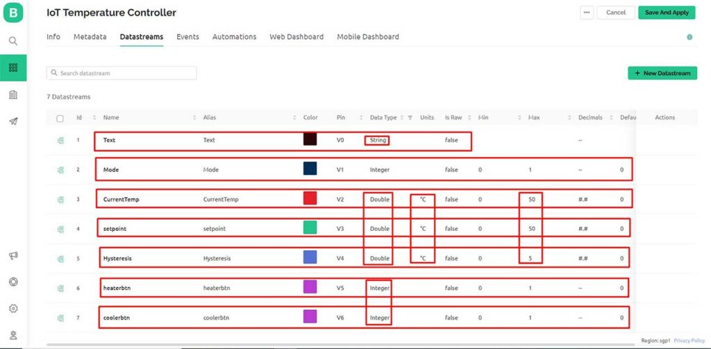
I have selected V0 to V6 respectively for our seven DataStreams. The Variable data type is Double for Current Temp, Setpoint, and Hysteresis. Integer datatype for buttons and string for text display. The maximum value for CurrentTemp and Setpoint is 50 °C. For hysteresis, the maximum value is set to 5 °C. The default value is set to 0 for all data streams.
Design the Blynk 2.0 Web Dashboard
After that move on to the web dashboard. In this section, you will be able to see some widgets for making your cool-looking web dashboard. We will use only the free widget available.
To display text I am using a Label widget. For showing the value of current Temperature, Temperature Setpoint, and Hysteresis I have selected Gauge. Similarly, switch widgets for automatic mode, heater, and cooler ON/OFF buttons. Finally, the Slider widget for Set Temperature & Set Hysteresis. In the settings of each widget, you have to give a name to the widget and you have to choose the data stream with which the widget will be connected. After setting up the widgets click on the save button to save the entire project.
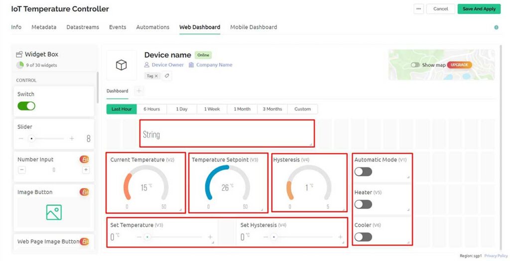
Now your Web Dashboard is Finally Ready. Using this Web Dashboard, you can monitor and control your device.
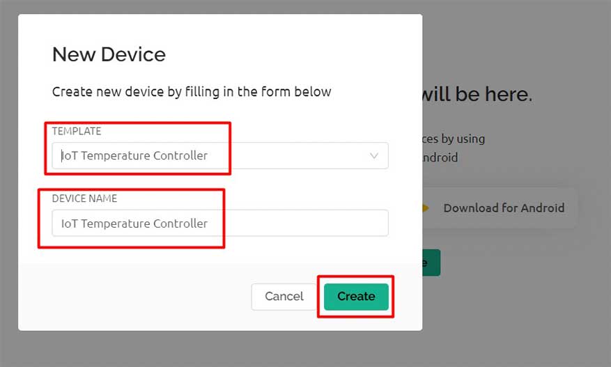
Adding New Device
Let’s Add a New Device. For that click on this search icon. Click on Add new Device. Select the first option, i.e. From Template. Choose your Template and give a Device Name then Click on Create. A New Device will be created.
You can see a snip of the code header file appear on the Dashboard. Click to copy it. Now you can paste this Template ID, Device Name, and Authentication token to the program code.
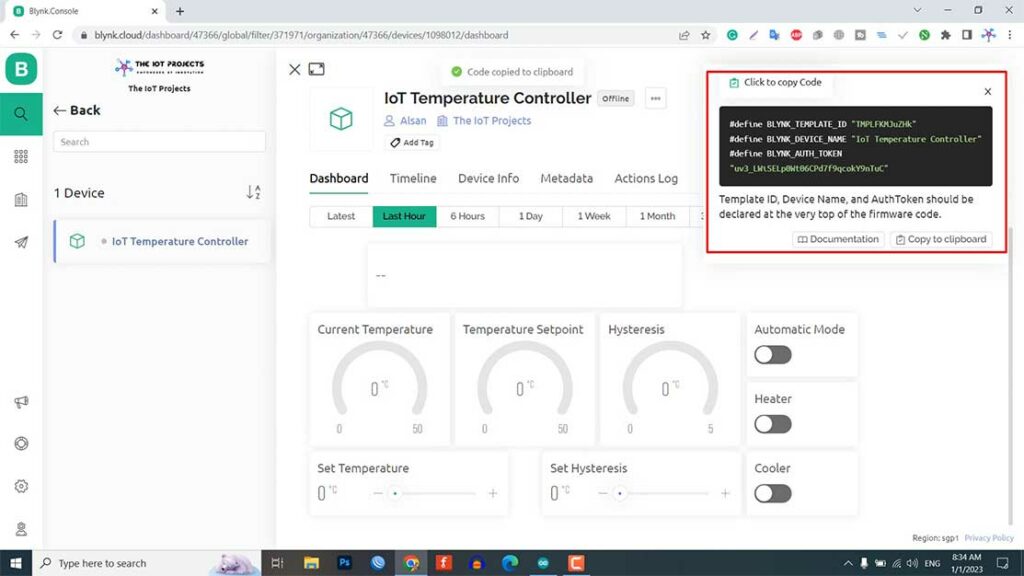
That’s all for setting up the Blynk IoT dashboard. We will set up the Blynk Mobile dashboard after uploading the program code.
Code/Program: IoT Temperature controller with ESP8266 & Blynk 2.0
This is the program code for the IoT Temperature controller with ESP8266 and Blynk 2.0
/**********************************************************************************
    TITLE:(IoT based Temperature Control System With ESP8266 + DS18B20 Dallas Temperature Sensor + 0.96 inch OLED Display
    + Auto and Manual Modes + Temperature Set Point and Hysteresis +  EEPROM + Real time feedback)
 **********************************************************************************/

/* Fill-in your Template ID (only if using Blynk.Cloud) */
#define BLYNK_TEMPLATE_ID "xxxx-xxxx-xxxx"
#define BLYNK_DEVICE_NAME "xxxx-xxxx-xxxx"
#define BLYNK_AUTH_TOKEN "xxxx-xxxx-xxxx"

// Your WiFi credentials.
// Set password to "" for open networks.
char ssid[] = "xxxx-xxxx-xxxx";
char pass[] = "xxxx-xxxx-xxxx";

//#define BLYNK_PRINT Serial
#include <ESP8266WiFi.h>
#include <BlynkSimpleEsp8266.h>
#include <Preferences.h>
Preferences pref;

#include <SPI.h>
#include <Wire.h>
#include <OneWire.h>
#include <DallasTemperature.h>
#include <Adafruit_GFX.h>
#include <Adafruit_SSD1306.h>
#define SCREEN_WIDTH 128 // OLED display width, in pixels
#define SCREEN_HEIGHT 64 // OLED display height, in pixels
#define OLED_RESET     -1 // Reset pin # (or -1 if sharing Arduino reset pin)
#define SCREEN_ADDRESS 0x3C ///< See datasheet for Address; 0x3D for 128x64, 0x3C for 128x32
Adafruit_SSD1306 display(SCREEN_WIDTH, SCREEN_HEIGHT, &Wire, OLED_RESET);

// Setpoint and hysteresis values (in degrees Celsius)
float setpoint = 0;
float hysteresis = 0;
float currentTemp = 0;

#define ONE_WIRE_BUS 13 //D7  of esp8266
OneWire oneWire(ONE_WIRE_BUS);
DallasTemperature sensors(&oneWire);


// define the GPIO connected with Relays
#define HEATING_PIN 14 //D5
#define COOLING_PIN 12 //D6
#define wifiLed   16   //D0

//Change the virtual pins according the rooms
#define VPIN_Text           V0
#define VPIN_Mode           V1
#define VPIN_currentTemp    V2
#define VPIN_setpoint       V3
#define VPIN_hysteresis     V4
#define VPIN_heaterbtn      V5
#define VPIN_coolerbtn      V6

// Relay and Mode State
bool heaterState = LOW; //Define integer to remember the toggle state for heater
bool coolerState = LOW; //Define integer to remember the toggle state for cooler
bool modeState = LOW; //Define integer to remember the mode

int wifiFlag = 0;


char auth[] = BLYNK_AUTH_TOKEN;

BlynkTimer timer;


// When App button is pushed - switch the state

BLYNK_WRITE(VPIN_heaterbtn) {
  heaterState = param.asInt();
  digitalWrite(HEATING_PIN, !heaterState);
  pref.putBool("Heater", heaterState);
}

BLYNK_WRITE(VPIN_coolerbtn) {
  coolerState = param.asInt();
  digitalWrite(COOLING_PIN, !coolerState);
  pref.putBool("Cooler", coolerState);
}

BLYNK_WRITE(VPIN_Mode) {
  modeState = param.asInt();
  pref.putBool("Mode", modeState);
}

BLYNK_WRITE(VPIN_setpoint) {
  setpoint = param.asFloat();
  pref.putBool("setemp", setpoint);
}

BLYNK_WRITE(VPIN_hysteresis) {
  hysteresis = param.asFloat();
  pref.putBool("Hyst", hysteresis);
}

void checkBlynkStatus() { // called every 2 seconds by SimpleTimer

  bool isconnected = Blynk.connected();
  if (isconnected == false) {
    wifiFlag = 1;
    Serial.println("Blynk Not Connected");
    digitalWrite(wifiLed, HIGH);
  }
  if (isconnected == true) {
    wifiFlag = 0;
    digitalWrite(wifiLed, LOW);
    Blynk.virtualWrite(VPIN_Text, "IoT Temperature Controller");
  }
}

BLYNK_CONNECTED() {
  // update the latest state to the server
  Blynk.virtualWrite(VPIN_Text, "IoT Temperature Controller");
  Blynk.virtualWrite(VPIN_Mode, modeState);
  Blynk.syncVirtual(VPIN_currentTemp);
  Blynk.syncVirtual(VPIN_setpoint);
  Blynk.syncVirtual(VPIN_hysteresis);
  Blynk.virtualWrite(VPIN_heaterbtn, heaterState);
  Blynk.virtualWrite(VPIN_coolerbtn, coolerState);

}

void readSensor() {

  // Send the command to get temperatures
  sensors.requestTemperatures();
  currentTemp = sensors.getTempCByIndex(0);
}

void sendSensor()
{
  readSensor();
  // You can send any value at any time.
  // Please don't send more that 10 values per second.
  Blynk.virtualWrite(VPIN_currentTemp, currentTemp);
  Blynk.virtualWrite(VPIN_Text, "IoT Temperature Controller");
}

void getRelayState()
{
  //Serial.println("reading data from NVS");
  modeState = pref.getBool("Mode", 0);
  Blynk.virtualWrite(VPIN_Mode, modeState);
  delay(200);
  heaterState = pref.getBool("Heater", 0);
  digitalWrite(HEATING_PIN, !heaterState);
  Blynk.virtualWrite(VPIN_heaterbtn, heaterState);
  delay(200);
  coolerState = pref.getBool("Cooler", 0);
  digitalWrite(COOLING_PIN, !coolerState);
  Blynk.virtualWrite(VPIN_coolerbtn, coolerState);
  delay(200);
  setpoint = pref.getBool("setemp", 0);
  Blynk.virtualWrite(VPIN_setpoint, setpoint);
  delay(200);
  hysteresis = pref.getBool("Hyst", 0);
  Blynk.virtualWrite(VPIN_hysteresis, hysteresis);
  delay(200);
}

void setup()
{
  Serial.begin(115200);
  //Open namespace in read-write mode
  pref.begin("Relay_State", false);

  pinMode(HEATING_PIN, OUTPUT);
  pinMode(COOLING_PIN, OUTPUT);
  pinMode(wifiLed, OUTPUT);

  // SSD1306_SWITCHCAPVCC = generate display voltage from 3.3V internally
  if (!display.begin(SSD1306_SWITCHCAPVCC, SCREEN_ADDRESS)) {
    Serial.println(F("SSD1306 allocation failed"));
    for (;;); // Don't proceed, loop forever
  }
  display.clearDisplay();
  display.setTextSize(2); // Draw 2X-scale text
  display.setTextColor(SSD1306_WHITE);
  display.setCursor(35, 0);
  display.println(" IoT ");
  display.setCursor(25, 20);
  display.println(" Temp. ");
  display.setCursor(0, 45);
  display.println("Controller");
  display.display();
  delay(2000); // Pause for 2 seconds

  //During Starting all Relays should TURN OFF
  digitalWrite(HEATING_PIN, !heaterState);
  digitalWrite(COOLING_PIN, !coolerState);

  sensors.begin();   // Enabling DS18B20 sensor
  digitalWrite(wifiLed, HIGH);

  //Blynk.begin(auth, ssid, pass);
  WiFi.begin(ssid, pass);
  timer.setInterval(2000L, checkBlynkStatus); // check if Blynk server is connected every 2 seconds
  timer.setInterval(1000L, sendSensor); // Sending Sensor Data to Blynk Cloud every 1 second
  Blynk.config(auth);
  delay(1000);

  getRelayState(); // Get the last state of Relays and Set values of Temp & Hysteresis

  Blynk.virtualWrite(VPIN_heaterbtn, heaterState);
  Blynk.virtualWrite(VPIN_coolerbtn, coolerState);
  Blynk.virtualWrite(VPIN_setpoint, setpoint);
  Blynk.virtualWrite(VPIN_hysteresis, hysteresis);
}

void loop()
{
  Blynk.run();
  timer.run();

  display.clearDisplay();
  display.setTextSize(1); // Draw 2X-scale text
  display.setTextColor(SSD1306_WHITE);
  display.setCursor(0, 0);
  display.println(" IoT Temp. Controller ");
  display.display();
  display.setTextSize(3); // Draw 2X-scale text
  display.setTextColor(SSD1306_WHITE);
  display.setCursor(0, 17);
  display.println(currentTemp);
  display.println(" ");
  display.drawRect(90, 17, 5, 5, WHITE);     // put degree symbol ( ° )
  display.setCursor(97, 17);
  display.println("C");
  display.display();

  Serial.println(hysteresis);
  display.setTextSize(1); // Draw 2X-scale text
  display.setTextColor(SSD1306_WHITE);
  display.setCursor(0, 57);
  display.print("Hys: ");
  display.print(hysteresis);
  display.display();
  Serial.println(setpoint);
  display.setTextSize(1); // Draw 2X-scale text
  display.setTextColor(SSD1306_WHITE);
  display.setCursor(67, 57);
  display.print("Temp: ");
  display.print(setpoint);
  display.display();

  // Check the mode and control the heater and cooler accordingly
  if (modeState == 1) {
    display.setTextSize(1); // Draw 2X-scale text
    display.setTextColor(SSD1306_WHITE);
    display.setCursor(32, 45);
    display.print("Auto Mode");
    display.display();
    // In auto mode, control the heater and cooler based on the current temperature and setpoint

    if (currentTemp > setpoint + hysteresis) {
      heaterState = 0;
      coolerState = 1;
      digitalWrite(HEATING_PIN, !heaterState);
      pref.putBool("Heater", heaterState);
      digitalWrite(COOLING_PIN, !coolerState);
      pref.putBool("Cooler", coolerState);
      Serial.println("Cooler ON");
      Blynk.virtualWrite(VPIN_heaterbtn, heaterState);
      Blynk.virtualWrite(VPIN_coolerbtn, coolerState);

    } else if (currentTemp < setpoint - hysteresis) {
      heaterState = 1;
      coolerState = 0;
      digitalWrite(HEATING_PIN, !heaterState);
      pref.putBool("Heater", heaterState);
      Serial.println("Heater ON");
      digitalWrite(COOLING_PIN, !coolerState);
      pref.putBool("Cooler", coolerState);
      Blynk.virtualWrite(VPIN_heaterbtn, heaterState);
      Blynk.virtualWrite(VPIN_coolerbtn, coolerState);
    } else {
      heaterState = 0;
      coolerState = 0;
      digitalWrite(HEATING_PIN, !heaterState);
      pref.putBool("Heater", heaterState);
      Serial.println("Heater OFF");
      digitalWrite(COOLING_PIN, !coolerState);
      pref.putBool("Cooler", coolerState);
      Serial.println("Cooler OFF");
      Blynk.virtualWrite(VPIN_heaterbtn, heaterState);
      Blynk.virtualWrite(VPIN_coolerbtn, coolerState);
    }
  }
  if (modeState == 0)
  {
    display.setTextSize(1); // Draw 2X-scale text
    display.setTextColor(SSD1306_WHITE);
    display.setCursor(32, 45);
    display.print("Manual Mode");
    display.display();
  }

  delay(3000);
}
Apart from this, you need to install the required library file in your Arduino IDE. Go to Sketch Menu > Include Library > Manage Libraries then search for the following library name and install them.
You can also download the library and install it from add zip library. Required Libraries links:
- Blynk Library (Version 1.1.0)
- DallasTemperature Library
- Adafruit SSD1306 Library
- Adafruit GFX Library
- Preferences Library
Now you can paste the Template ID, Device Name, and Authentication token to the program code in the following lines.
/* Fill-in your Template ID (only if using Blynk.Cloud) */
#define BLYNK_TEMPLATE_ID "xxxx-xxxx-xxxx"
#define BLYNK_DEVICE_NAME "xxxx-xxxx-xxxx"
#define BLYNK_AUTH_TOKEN "xxxx-xxxx-xxxx"
Update your WiFi SSID and Password from this line of code.
// Your WiFi credentials.
// Set password to "" for open networks.
char ssid[] = "xxxx-xxxx-xxxx";
char pass[] = "xxxx-xxxx-xxxx";
After necessary customization, it’s time to upload code to this ESP8266 NodeMCU Development board. So Go to Tools > Board > ESP8266 Boards > NodeMCU 1.0 (ESP8266-12E Module). Again go to Tools > Port Then choose the correct COM Port. Finally, hit that upload button.
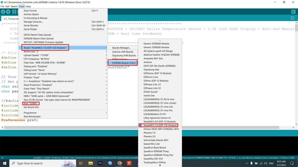
It takes a few seconds to compile and upload the code. And that’s it! You now have a working temperature control system that you can access and control remotely from anywhere in the world.
Code/Program: Explanation
Certainly. Here is a brief explanation of the above Program code:
Defining Constants, Variables, & Libraries
The first section of the code includes Blynk Credentials like: Template ID, Device Name, and Authentication token that are used later in the code.
/* Fill-in your Template ID (only if using Blynk.Cloud) */
#define BLYNK_TEMPLATE_ID "xxxx-xxxx-xxxx"
#define BLYNK_DEVICE_NAME "xxxx-xxxx-xxxx"
#define BLYNK_AUTH_TOKEN "xxxx-xxxx-xxxx"
The next section of the code defines a number of constants and variables that are used throughout the code. These include the SSID and password for the WiFi network, include required libraries, the virtual pin numbers for the Blynk app, the pin numbers for the heating and cooling relays, and the setpoint, hysteresis, and current temperature values.
#include <ESP8266WiFi.h>
#include <BlynkSimpleEsp8266.h>
#include <Preferences.h>
Preferences pref;

#include <SPI.h>
#include <Wire.h>
#include <OneWire.h>
#include <DallasTemperature.h>
#include <Adafruit_GFX.h>
#include <Adafruit_SSD1306.h>
#define SCREEN_WIDTH 128 // OLED display width, in pixels
#define SCREEN_HEIGHT 64 // OLED display height, in pixels
#define OLED_RESET     -1 // Reset pin # (or -1 if sharing Arduino reset pin)
#define SCREEN_ADDRESS 0x3C ///< See datasheet for Address; 0x3D for 128x64, 0x3C for 128x32
Adafruit_SSD1306 display(SCREEN_WIDTH, SCREEN_HEIGHT, &Wire, OLED_RESET);

// Setpoint and hysteresis values (in degrees Celsius)
float setpoint = 0;
float hysteresis = 0;
float currentTemp = 0;

#define ONE_WIRE_BUS 13 //D7  of esp8266
OneWire oneWire(ONE_WIRE_BUS);
DallasTemperature sensors(&oneWire);


// define the GPIO connected with Relays
#define HEATING_PIN 14 //D5
#define COOLING_PIN 12 //D6
#define wifiLed   16   //D0

//Change the virtual pins according the rooms
#define VPIN_Text           V0
#define VPIN_Mode           V1
#define VPIN_currentTemp    V2
#define VPIN_setpoint       V3
#define VPIN_hysteresis     V4
#define VPIN_heaterbtn      V5
#define VPIN_coolerbtn      V6

// Relay and Mode State
bool heaterState = LOW; //Define integer to remember the toggle state for heater
bool coolerState = LOW; //Define integer to remember the toggle state for cooler
bool modeState = LOW; //Define integer to remember the mode

int wifiFlag = 0;


char auth[] = BLYNK_AUTH_TOKEN;

BlynkTimer timer;
Setup Function
The setup function initializes the OLED display, WiFi connection, and Blynk app. It also retrieves the saved system state from the EEPROM and sets the state of the heating and cooling relays accordingly.
void setup()
{
  Serial.begin(115200);
  //Open namespace in read-write mode
  pref.begin("Relay_State", false);

  pinMode(HEATING_PIN, OUTPUT);
  pinMode(COOLING_PIN, OUTPUT);
  pinMode(wifiLed, OUTPUT);

  // SSD1306_SWITCHCAPVCC = generate display voltage from 3.3V internally
  if (!display.begin(SSD1306_SWITCHCAPVCC, SCREEN_ADDRESS)) {
    Serial.println(F("SSD1306 allocation failed"));
    for (;;); // Don't proceed, loop forever
  }
  display.clearDisplay();
  display.setTextSize(2); // Draw 2X-scale text
  display.setTextColor(SSD1306_WHITE);
  display.setCursor(35, 0);
  display.println(" IoT ");
  display.setCursor(25, 20);
  display.println(" Temp. ");
  display.setCursor(0, 45);
  display.println("Controller");
  display.display();
  delay(2000); // Pause for 2 seconds

  //During Starting all Relays should TURN OFF
  digitalWrite(HEATING_PIN, !heaterState);
  digitalWrite(COOLING_PIN, !coolerState);

  sensors.begin();   // Enabling DS18B20 sensor
  digitalWrite(wifiLed, HIGH);

  //Blynk.begin(auth, ssid, pass);
  WiFi.begin(ssid, pass);
  timer.setInterval(2000L, checkBlynkStatus); // check if Blynk server is connected every 2 seconds
  timer.setInterval(1000L, sendSensor); // Sending Sensor Data to Blynk Cloud every 1 second
  Blynk.config(auth);
  delay(1000);

  getRelayState(); // Get the last state of Relays and Set values of Temp & Hysteresis

  Blynk.virtualWrite(VPIN_heaterbtn, heaterState);
  Blynk.virtualWrite(VPIN_coolerbtn, coolerState);
  Blynk.virtualWrite(VPIN_setpoint, setpoint);
  Blynk.virtualWrite(VPIN_hysteresis, hysteresis);
}
Loop Function
The loop function begins by reading the temperature from the DS18B20 sensor and sending it to the OLED Display & Blynk app via the VPIN_currentTemp virtual pin. The OLED display will show the Device Name and other information about the system, such as the current temperature, setpoint, hysteresis, and modes.
  sensors.requestTemperatures();
  currentTemp = sensors.getTempCByIndex(0);
  Blynk.virtualWrite(VPIN_currentTemp, currentTemp);
  Blynk.virtualWrite(VPIN_Text, "IoT Temperature Controller");

  display.clearDisplay();
  display.setTextSize(1); // Draw 2X-scale text
  display.setTextColor(SSD1306_WHITE);
  display.setCursor(0, 0);
  display.println(" IoT Temp. Controller ");
  display.display();
  display.setTextSize(3); // Draw 2X-scale text
  display.setTextColor(SSD1306_WHITE);
  display.setCursor(0, 17);
  display.println(currentTemp);
  display.println(" ");
  display.drawRect(90, 17, 5, 5, WHITE);     // put degree symbol ( ° )
  display.setCursor(97, 17);
  display.println("C");
  display.display();

  Serial.println(hysteresis);
  display.setTextSize(1); // Draw 2X-scale text
  display.setTextColor(SSD1306_WHITE);
  display.setCursor(0, 57);
  display.print("Hys: ");
  display.print(hysteresis);
  display.display();
  Serial.println(setpoint);
  display.setTextSize(1); // Draw 2X-scale text
  display.setTextColor(SSD1306_WHITE);
  display.setCursor(67, 57);
  display.print("Temp: ");
  display.print(setpoint);
  display.display();
Now the system checks the modeState variable to determine whether the system is operating in automatic or manual mode.
// Check the mode and control the heater and cooler accordingly
  if (modeState == 1) {
    display.setTextSize(1); // Draw 2X-scale text
    display.setTextColor(SSD1306_WHITE);
    display.setCursor(32, 45);
    display.print("Auto Mode");
    display.display();
    // In auto mode, control the heater and cooler based on the current temperature and setpoint
If in automatic mode, the code compares the current temperature to the setpoint and hysteresis values to determine whether the heating or cooling relays should be activated. If the current temperature is below the setpoint minus the hysteresis value, the heating relay is activated. Similarly, If the current temperature is above the setpoint plus the hysteresis value, the cooling relay is activated. If the current temperature is within the setpoint plus or minus the hysteresis value, both relays are deactivated.
    if (currentTemp > setpoint + hysteresis) {
      heaterState = 0;
      coolerState = 1;
      digitalWrite(HEATING_PIN, !heaterState);
      pref.putBool("Heater", heaterState);
      digitalWrite(COOLING_PIN, !coolerState);
      pref.putBool("Cooler", coolerState);
      Serial.println("Cooler ON");
      Blynk.virtualWrite(VPIN_heaterbtn, heaterState);
      Blynk.virtualWrite(VPIN_coolerbtn, coolerState);

    } else if (currentTemp < setpoint - hysteresis) {
      heaterState = 1;
      coolerState = 0;
      digitalWrite(HEATING_PIN, !heaterState);
      pref.putBool("Heater", heaterState);
      Serial.println("Heater ON");
      digitalWrite(COOLING_PIN, !coolerState);
      pref.putBool("Cooler", coolerState);
      Blynk.virtualWrite(VPIN_heaterbtn, heaterState);
      Blynk.virtualWrite(VPIN_coolerbtn, coolerState);
    } else {
      heaterState = 0;
      coolerState = 0;
      digitalWrite(HEATING_PIN, !heaterState);
      pref.putBool("Heater", heaterState);
      Serial.println("Heater OFF");
      digitalWrite(COOLING_PIN, !coolerState);
      pref.putBool("Cooler", coolerState);
      Serial.println("Cooler OFF");
      Blynk.virtualWrite(VPIN_heaterbtn, heaterState);
      Blynk.virtualWrite(VPIN_coolerbtn, coolerState);
    }
  }
If in manual mode, the code simply sets the heating and cooling relays according to the state of the heaterState and coolerState variables, which are controlled by the VPIN_heaterbtn and VPIN_coolerbtn virtual pins in the Blynk app.
  if (modeState == 0)
  {
    display.setTextSize(1); // Draw 2X-scale text
    display.setTextColor(SSD1306_WHITE);
    display.setCursor(32, 45);
    display.print("Manual Mode");
    display.display();
  }
BLYNK_WRITE(VPIN_heaterbtn) {
  heaterState = param.asInt();
  digitalWrite(HEATING_PIN, !heaterState);
  pref.putBool("Heater", heaterState);
}

BLYNK_WRITE(VPIN_coolerbtn) {
  coolerState = param.asInt();
  digitalWrite(COOLING_PIN, !coolerState);
  pref.putBool("Cooler", coolerState);
}
BLYNK_WRITE functions
There are also several BLYNK_WRITE functions that are called whenever the user interacts with certain virtual pins in the Blynk app. For example, the VPIN_heaterbtn virtual pin controls the heaterState variable, and the VPIN_coolerbtn virtual pin controls the coolerState variable. The VPIN_Mode virtual pin controls the modeState variable, which determines whether the system is operating in automatic or manual mode.
BLYNK_WRITE(VPIN_heaterbtn) {
  heaterState = param.asInt();
  digitalWrite(HEATING_PIN, !heaterState);
  pref.putBool("Heater", heaterState);
}

BLYNK_WRITE(VPIN_coolerbtn) {
  coolerState = param.asInt();
  digitalWrite(COOLING_PIN, !coolerState);
  pref.putBool("Cooler", coolerState);
}

BLYNK_WRITE(VPIN_Mode) {
  modeState = param.asInt();
  pref.putBool("Mode", modeState);
}

BLYNK_WRITE(VPIN_setpoint) {
  setpoint = param.asFloat();
  pref.putBool("setemp", setpoint);
}

BLYNK_WRITE(VPIN_hysteresis) {
  hysteresis = param.asFloat();
  pref.putBool("Hyst", hysteresis);
}
Other BLYNK Functions
Finally, the code includes a number of functions that are called by the Blynk app to read and write data to and from the system.
BLYNK_CONNECTED
These functions include BLYNK_CONNECTED, which is called when the system connects to the Blynk app.
BLYNK_CONNECTED() {
  // update the latest state to the server
  Blynk.virtualWrite(VPIN_Text, "IoT Temperature Controller");
  Blynk.virtualWrite(VPIN_Mode, modeState);
  Blynk.syncVirtual(VPIN_currentTemp);
  Blynk.syncVirtual(VPIN_setpoint);
  Blynk.syncVirtual(VPIN_hysteresis);
  Blynk.virtualWrite(VPIN_heaterbtn, heaterState);
  Blynk.virtualWrite(VPIN_coolerbtn, coolerState);

}
checkBlynkStatus Function
The checkBlynkStatus function is called every 2 seconds by SimpleTimer. To check wifi and blynk connection.
void checkBlynkStatus() { //

  bool isconnected = Blynk.connected();
  if (isconnected == false) {
    wifiFlag = 1;
    Serial.println("Blynk Not Connected");
    digitalWrite(wifiLed, HIGH);
  }
  if (isconnected == true) {
    wifiFlag = 0;
    digitalWrite(wifiLed, LOW);
    Blynk.virtualWrite(VPIN_Text, "IoT Temperature Controller");
  }
}
I hope this explanation helps! Now let’s set up the Blynk App for Mobile.
Blynk IoT 2.0 Mobile App Setup
Download the blynk application into your mobile.
- New Blynk Mobile App (Android)
- New Blynk Mobile App (iOS)
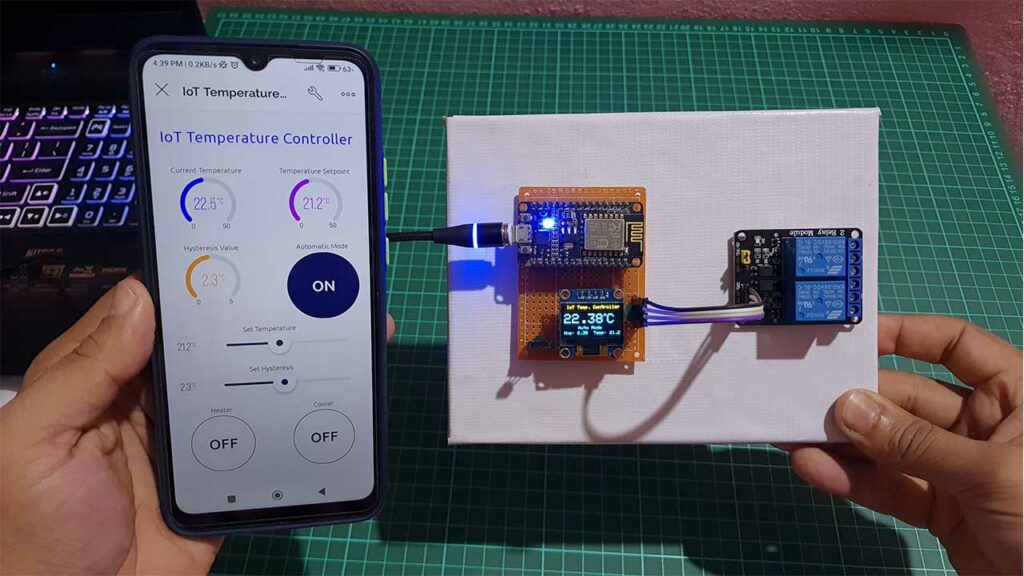
After installing the application login into your account. You will see a new device “IoT Temperature Controller” Click on it and start configuring the mobile dashboard. As done on the web dashboard I have used one Label widget, three gauge widgets, two slider widgets, and three button widgets.
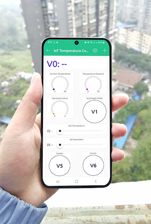
See the above image for the step-by-step configuration and setup of each widget used in this project.
So, that’s all for the Mobile dashboard setup. Now you can see the data of your blynk device in your mobile app and in the web dashboard as well.
Testing: IoT Temperature Control System with ESP8266 & Blynk
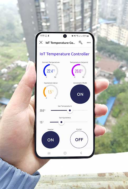
Here is a demonstration of how this IoT temperature control system with ESP8266 project works:
ESP8266 microcontroller connects to a WiFi network and the Blynk app, allowing the user to control and monitor the system remotely from anywhere in the world. DS18B20 temperature sensor measures the ambient temperature and sends the data to the ESP8266.
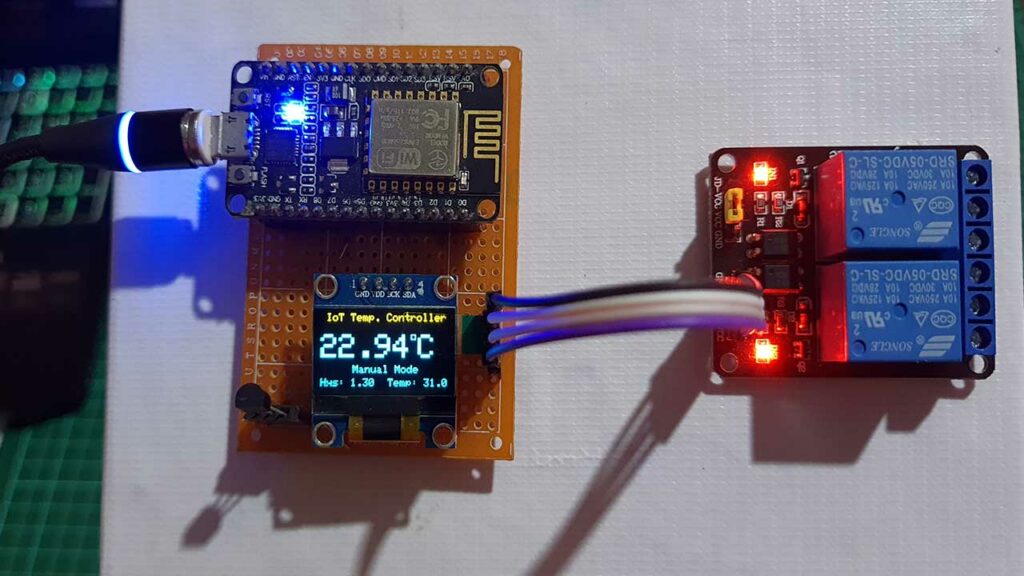
The OLED display will show the Device Name and other information about the system, such as the current temperature, setpoint, hysteresis, and modes.
You can set a temperature set point and a hysteresis value using a slider on the Blynk app. This device can operate in either automatic or manual mode, depending on the user’s preference.
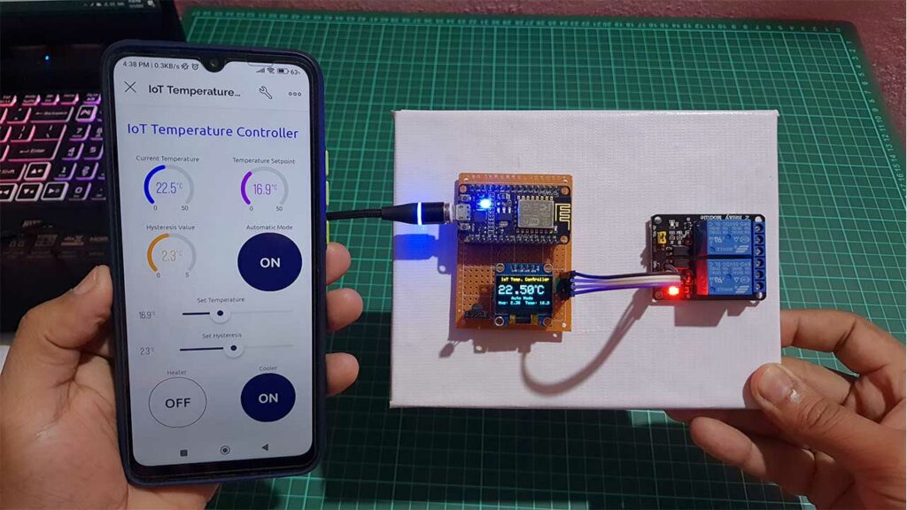
In automatic mode, the system will compare the current temperature to the setpoint and hysteresis values to determine whether the heating or cooling relays should be activated. If the current temperature is below the setpoint minus the hysteresis value, the heating relay will be activated. Similarly, If the current temperature is above the setpoint plus the hysteresis value, the cooling relay will be activated. If the current temperature is within the setpoint plus or minus the hysteresis value, both relays will be deactivated. You can also see real-time feedback on the dashboard.
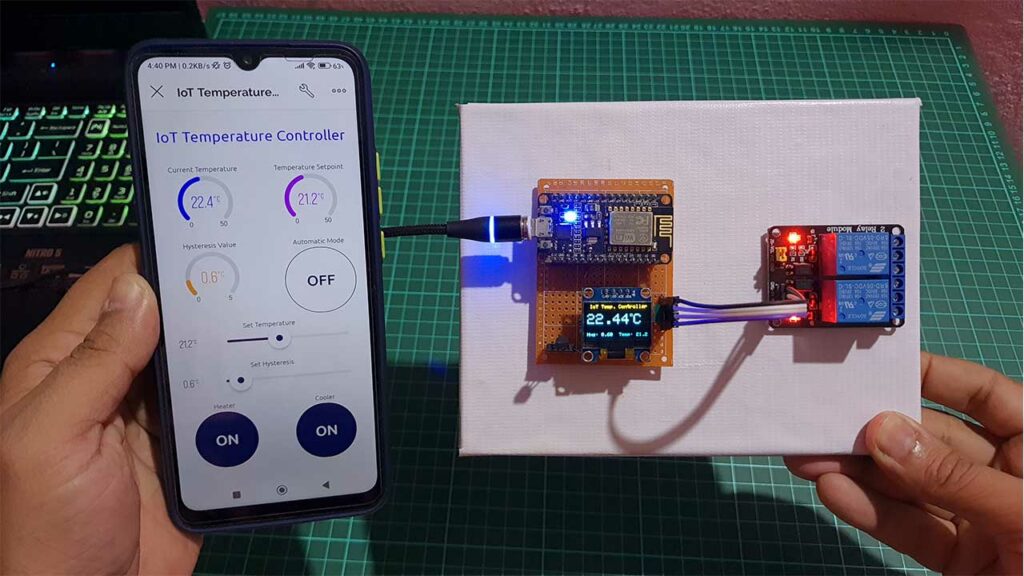
In manual mode, the user can manually control the state of the heating and cooling relays using the Blynk app.
This system also uses the EEPROM (Electrically Erasable Programmable Read-Only Memory) of the ESP8266 to store the state of the system between power cycles. allowing the system to retain its settings even when the power is turned off.
Video tutorial & Guide
Conclusion
You can monitor and control the system remotely using the Blynk app, allowing them to maintain a comfortable temperature in their home or office from anywhere. And that’s it! With a little bit of coding and some basic electronics skills, you can build your own IoT temperature control system using the ESP8266, DS18B20, OLED Display, and Blynk app. Thanks for reading, and happy building!


Hi, nice project.
Is possible to change program for blynk legacy first version?
thanks
Hi, Nice project! im trying to build this but the boolean function for the hystherise and the temperature doesnt work. it does work for the mode state. can anyone help me out?
Very nice project,
The only thing that is a bit strange: In manual mode it is possible to put on the heater and cooler at the samen time…
How to make only the temperature displayed?
In what blynk or in OLED?
Thank you, I’ve been dreaming of something like this for a long time, but today it happened, it works perfectly
Hola buenas tardes y gracias por publicar este proyecto que me parece muy interesante. Lo he realizado solo para controlar la calefacción y en principio me funciona correctamente , pero tengo un problema que la temperatura que me marca la pantalla Oled es superior a la que realmente existe comparándola con un termómetro convencional, es decir que siempre me marca 2 o 3 grados de más y a veces hasta 4 grados. He probado la sonda DS18B20 en otro circuito aparte y la lectura es bastante precisa. También la pantalla Oled a veces falla se montan los números y las frases y al poco rato se estabiliza.
No creo que el problema venga por haber suprimido parte del código perteneciente a refrigeración pués por lo demás y desde la aplicación Blynk funciona correctamente
Espero me ayuden y felicidades por el artículo
Muchas gracias
Un saludo
Ciao, Bel progetto, ho provato a realizzarlo ma non riesco a compilate, mi da errore di compilazione:
Error while detecting libraries included by C:\Users\User\AppData\Local\Temp\arduino_build_360063\sketch\iot_sketch_mar15a_15032024.ino.cpp
le librerie sono tutte presenti, se qualcuno può aiutare.
Grazie.
Saluti