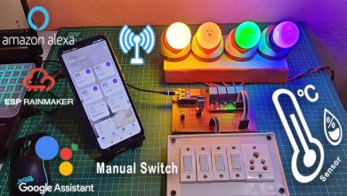
IoT Temperature & Humidity Monitoring & Control System using ESP32 & Blynk 2.0
Temperature & Humidity Controller System with ESP32 & Blynk IoT
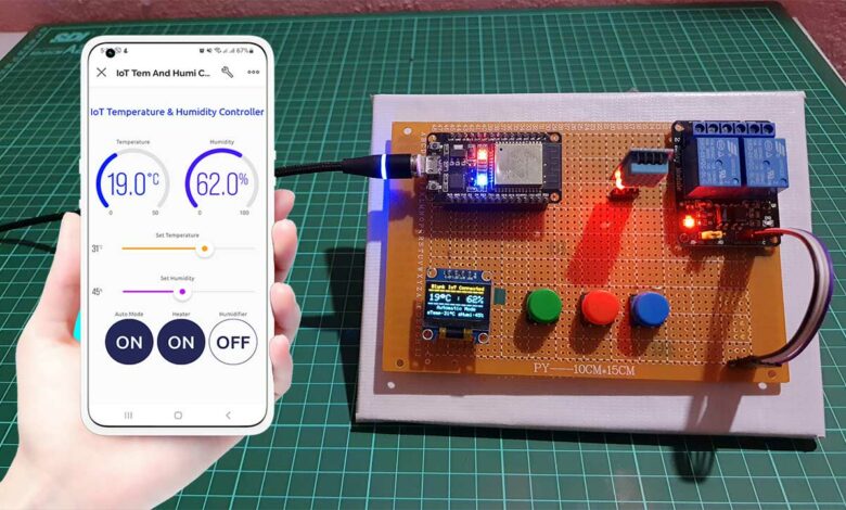
In this project, we will make a temperature and Humidity monitoring and control system using ESP32 WiFi module and view data on the blynk 2.0 IoT App.
- Overview: IoT Temperature & Humidity Monitoring & Control System
- Components Required
- Circuit Diagram & Connection
- Project PCB Gerber File & PCB Ordering Online
- Blynk 2.0 Web Dashboard Setup
- Adding New Device to Blynk Dashboard
- Source Code/Program
- Blynk IoT Mobile App Dashboard
- Testing: IoT Temperature & Humidity Monitoring & Control System with ESP32 & Blynk
- Conclusion
Overview: IoT Temperature & Humidity Monitoring & Control System
There are many potential applications for an IoT-based temperature and humidity control system. Some examples include:
- Controlling the temperature and humidity in a greenhouse.
- Maintaining optimal conditions in a mushroom grow room.
- Regulating temperature and humidity in a wine cellar.
- Creating the perfect conditions for aging cheese.
- Keeping a server room at the optimal temperature and humidity for equipment performance.
- Maintaining the ideal conditions for drying and storing foods.
- Optimizing the conditions for storing and displaying museum artifacts.
- Regulating the temperature and humidity in a laboratory, incubator, commercial buildings, etc.
By the end of this tutorial, I will show you how this small device helped me to grow mushrooms at extremely low temperatures.
Features of IoT Temperature & Humidity Controller
Some of the features of this project include:
Temperature and Humidity control
The program allows the user to set the target temperature and humidity levels. Then the system will turn ON and OFF the heating and humidifying devices as needed to try to maintain those levels.
To measure the temperature and Humidity of the surroundings I am using a cheap and easily available DHT11 sensor. You can also use the DHT22 sensor.
Mode feature
The program has a mode feature that the user can toggle in the Blynk app to switch between automatic and manual modes.
When the system is in auto mode, it continuously reads the current temperature and humidity levels from a sensor and compares them to the target temperature and humidity levels. Then the system will turn ON and OFF the heating and humidifying devices as needed to maintain those target levels.
When the system is in manual mode. The heating and humidifying devices are controlled manually by the user rather than being automatically turned ON and OFF to maintain a target temperature and humidity level.
OLED display
The 0.96-inch OLED display will display the Blynk IoT Connection status, current temperature, and Humidity, Operating Mode, Temperature set value, and humidity set value.
Manual control
The program has three buttons connected to the ESP32 that allow the user to manually control the devices. It comes in handy when you don’t have a mobile phone or your system is not connected to the internet. Because this device works even in offline mode. The first Green button allows the user to switch between modes. The other two red and blue buttons allow the user to control the heating and humidifying devices.
WiFi & Cloud Connectivity
The program uses the WiFi library to connect to a WiFi network and the Blynk library to connect to the Blynk cloud service and communicate with the Blynk app. The blynk app will show you DHT11 sensor data current temperature and humidity. Using the blynk IoT app we can also set temperature and Humidity threshold values. Additionally, you can switch between modes as well as control devices manually when needed.
Data Storage on EEPROM
The program uses the Preferences library to store data (e.g. ON or OFF state of the heating and humidifying device, auto or manual mode of the system, target temperature & humidity). This allows the device to remember its previous state and settings even if it is powered off.
So, without further delay, let’s get started with the hardware you’ll need for this project:
Components Required
Following is the list of the hardware components that are required for making this project. You can easily purchase them from the links provided below.
| S.N | COMPONENTS NAME | QUANTITY | PURCHASE LINKS |
|---|---|---|---|
| 1 | ESP32 WiFi Module | 1 | Amazon | AliExpress |
| 2 | DHT11 Temperature & Humidity Sensor | 1 | Amazon | AliExpress |
| 3 | 0.96" I2C OLED Display | 1 | Amazon | AliExpress |
| 4 | 5V 2-Channel Relay | 1 | Amazon | AliExpress |
| 5 | 220V 100W Halogen Bulb | 1 | Amazon | AliExpress |
| 6 | Mist Maker (Humidifier) | 1 | Amazon | AliExpress |
| 7 | Jumper Cables | 10 | Amazon | AliExpress |
| 7 | Zero PCB board | 1 | Amazon | AliExpress |
Circuit Diagram & Connection
Now that we have all of the materials that we need, let’s start by setting up the hardware.
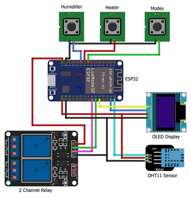
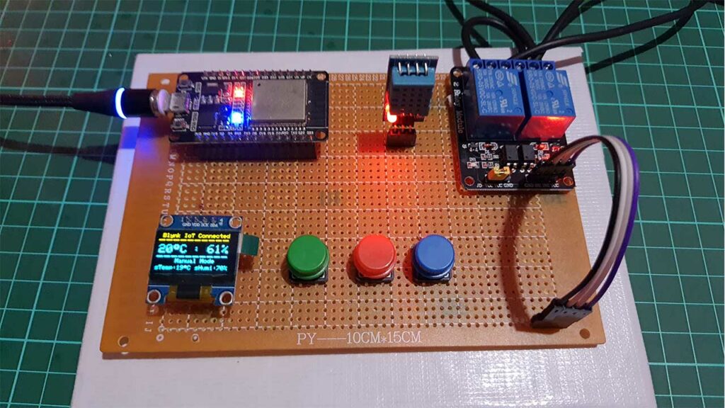
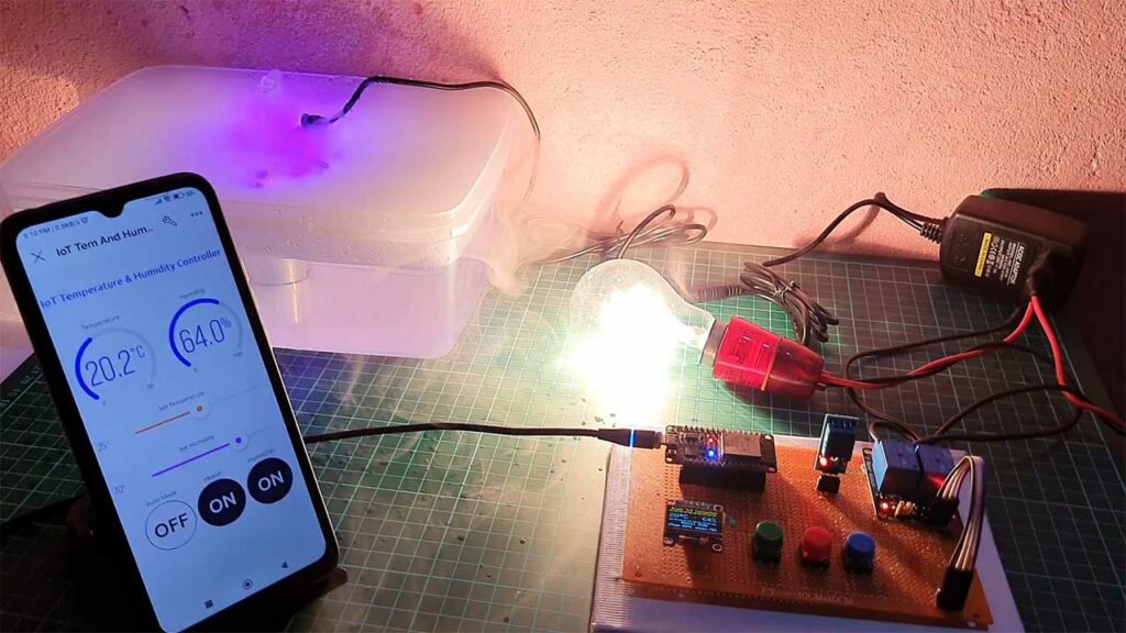
First, connect the OLED display to the ESP32 using I2C (SCL & SDA) pins to D22 and D21 pins. Next, connect the DHT11 sensor to the ESP32 D23 pin. Then, connect the two-channel relay to the ESP32 D18 and D19 pins. While VCC is connected to the Vin pin for a 5V power supply. Interface buttons to D25, D26, and D27 pins respectively. Connect all GND pins to GND and VCC pins to the 3.3V pin of the ESP32 WiFi Module.
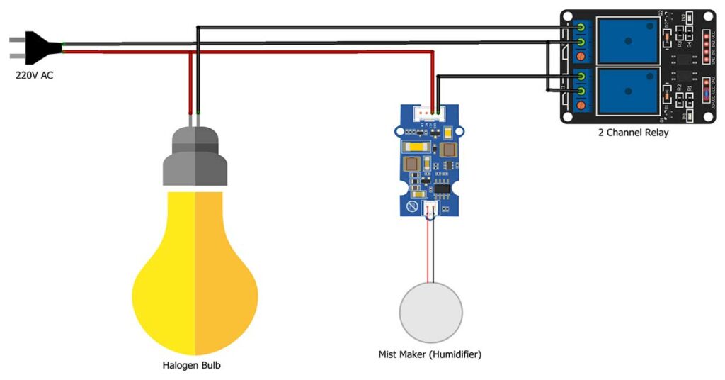
Now connect the Heating component (Halogen Bulb in my case) and the Mist maker (humidifier) to the relay module and power supply. Here you are dealing with AC current so be careful while connecting wires.
So we have a complete hardware setup for IoT Temperature & Humidity Monitoring & Control System using ESP32.
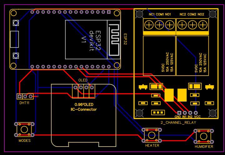
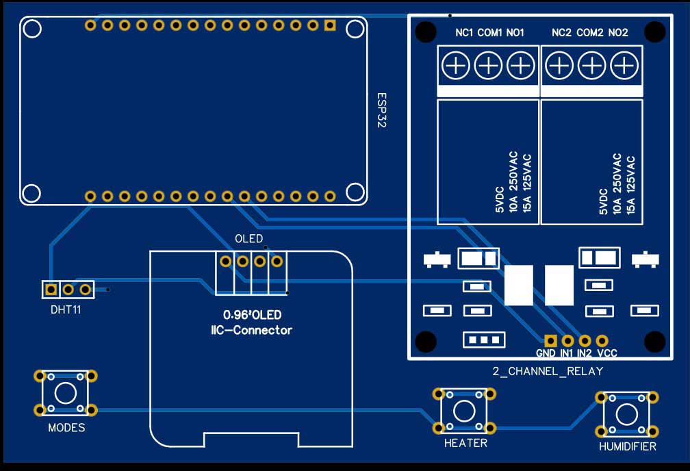
Project PCB Gerber File & PCB Ordering Online
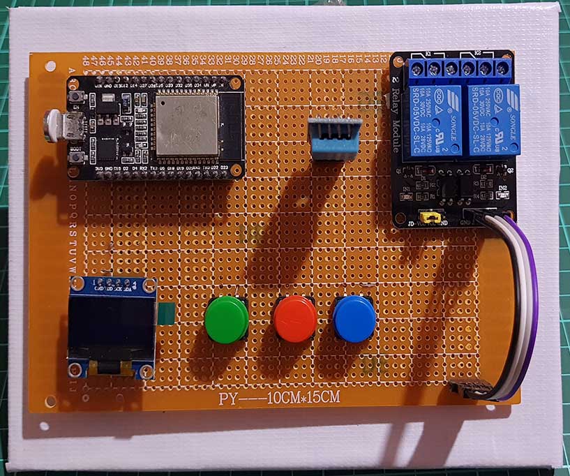
If you don’t want to assemble the circuit on a zero PCB and you want PCB for the project, then here is the PCB for you. The PCB Board for this project looks something like below.

The Gerber File for the PCB is given below. You can simply download the Gerber File and order the PCB from PCBWay.com.
Now you can visit the PCBWay official website by clicking here: PCBWay.com. So you will be directed to the PCBWay website. Currently, PCBWay is celebrating their 10th Anniversary with amazing offers and special events! If you’re into electronics and PCB projects like me, you definitely don’t want to miss out on this.

PCBWay has been a trusted partner for PCB prototyping, manufacturing, and assembly for a decade now. To celebrate this milestone, they have a bunch of exciting deals and giveaways lined up. You can visit their special anniversary page at www.pcbway.com/activity/anniversary10th.html to participate.
I’ve been using PCBWay for my own projects, and their quality and customer service have always been top-notch. Whether you’re a hobbyist or a professional, PCBWay’s services are perfect for bringing your ideas to life.
And during this anniversary celebration, they are offering discounts, free trials, and even a chance to win some fantastic prizes!
So, what are you waiting for? Head over to PCBWay.com and join in the celebration. Let’s make some great projects together. Thanks again to PCBWay for sponsoring this project.
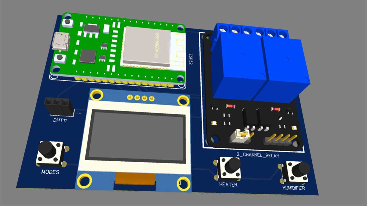
Now, you can assemble the components on the PCB Board.
Blynk 2.0 Web Dashboard Setup
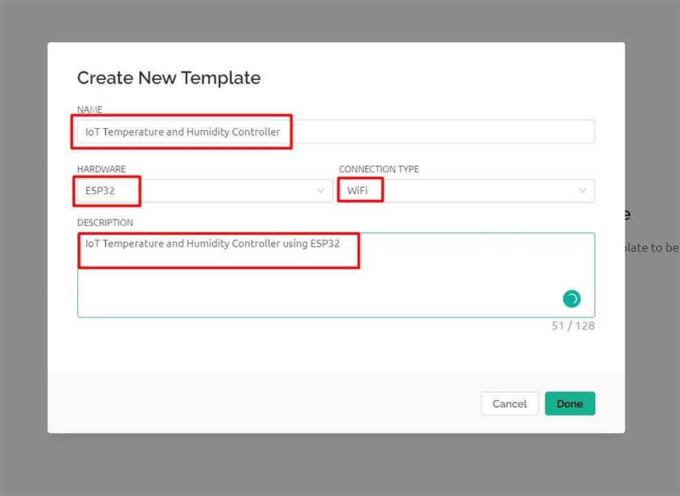
Now, let’s set up the IoT part of this project. First, we’ll set up the Blynk dashboard. Sign up using your Blynk email and password, and then create a new template. Assign a name, hardware, and connection type to the template.
From the web dashboard, create eight widgets:
- 1 Label widget
- 2 Gauge widgets
- 2 Slider widgets and
- 3 Button widgets
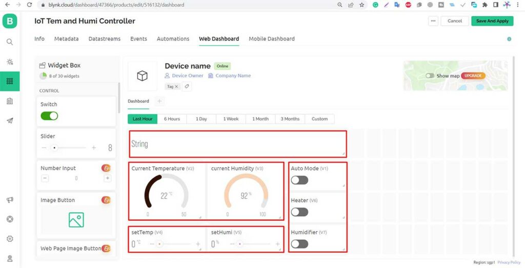
You can resize, drag, and drop the widgets to your desired location.
Configure Widgets with Datastream
For the Label widget, choose the virtual pin V0 and set the data type to string. This will be used to display custom text messages.

For the current temperature display in the Gauge, select the virtual pin V2 and set the data type to double. Set the units to degree Celsius and the maximum value to 50.

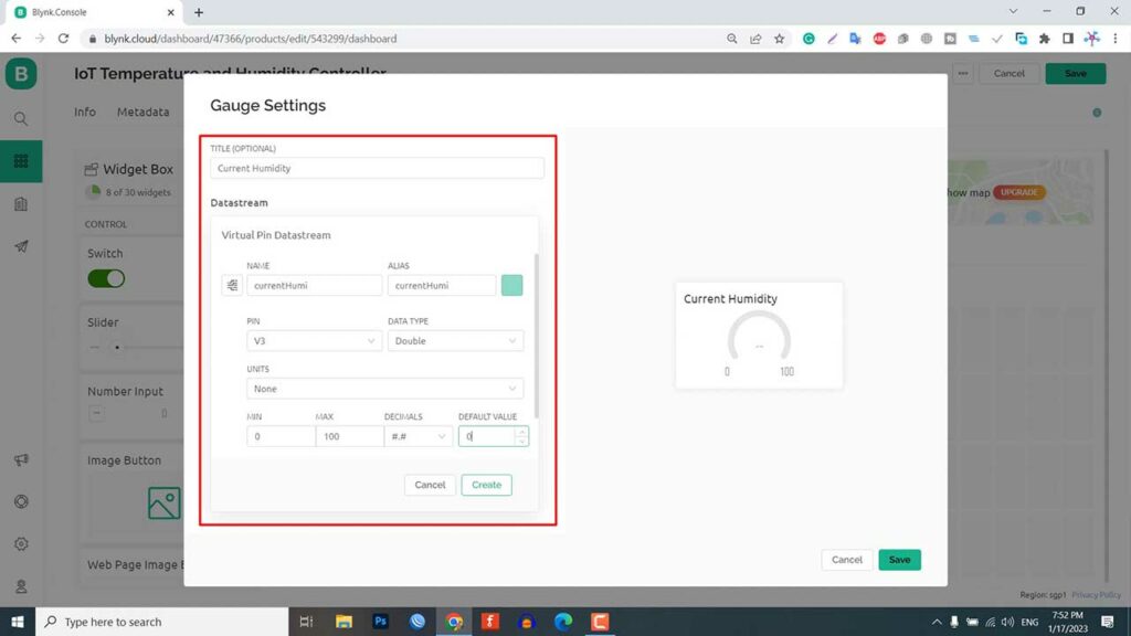
Similarly, for the current humidity, select the virtual pin V3 and set the data type to double. Set the units to percentage and the maximum value to 100.
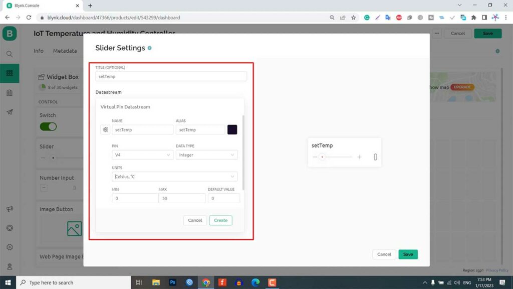
For the set temperature slider, assign the virtual pin V4 and set the data type to integer. This slider is used to set the temperature threshold value.
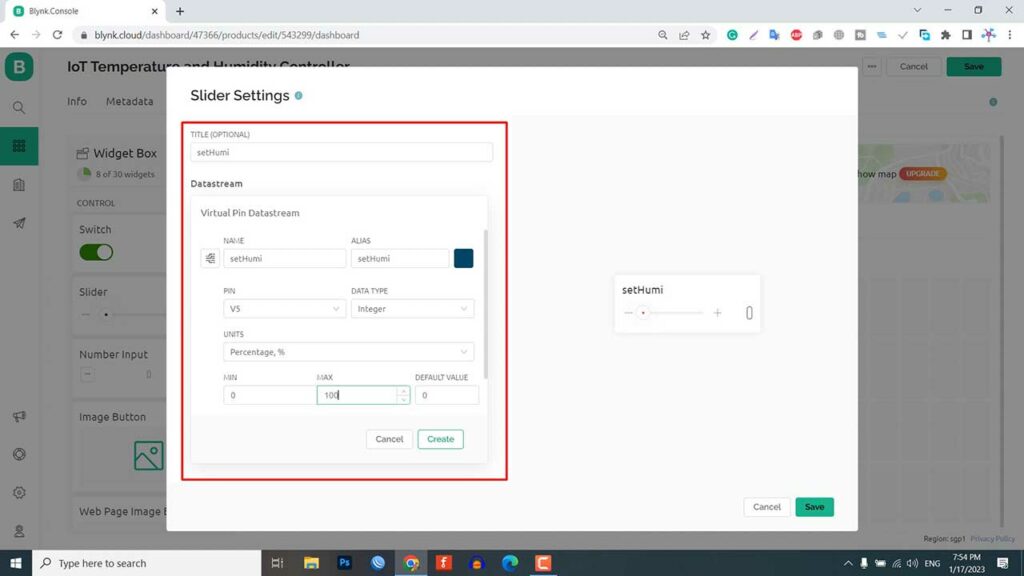
Similarly, for the set humidity slider widget, assign the virtual pin V5, set the data type to an integer, and set the maximum value to 100%. It is used to set the humidity threshold value.
Now, configure the button for switching modes. Name the widget “Auto Mode” and assign the virtual pin V1. Set the data type to integer. If this button is in the “off” state, the device will be set to manual mode.

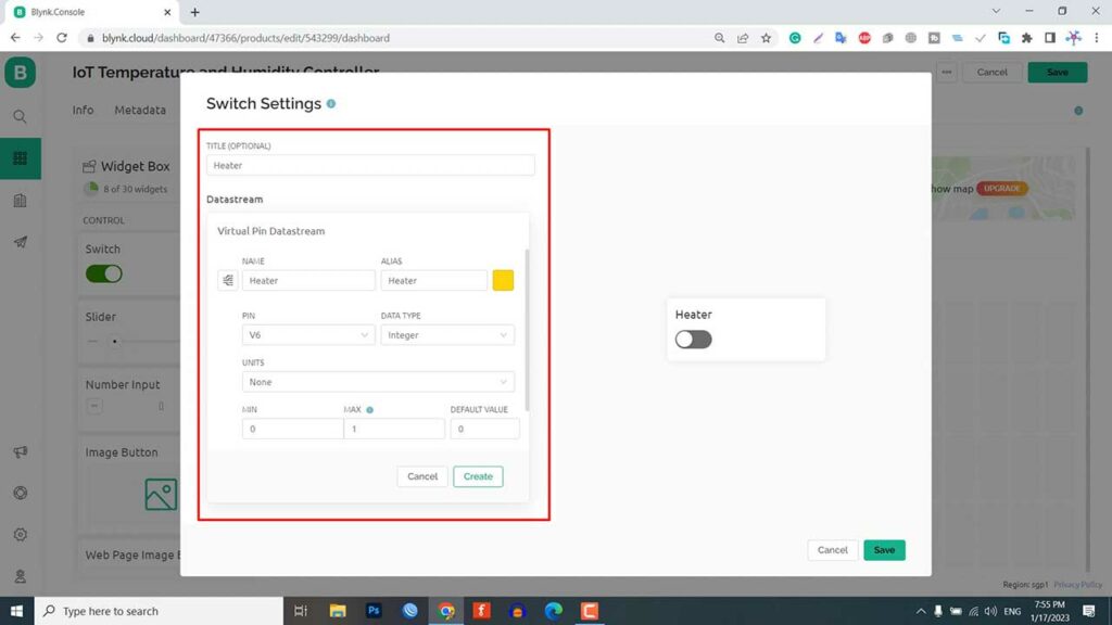
To turn the heater ON and OFF, assign the virtual pin V6 and set the data type to integer.
Finally, to control the humidifier, assign the virtual pin V7 and set the data type to integer. Click “save” to save the entire setup.

In addition to the web dashboard, you can also set up your mobile app dashboard. We will set up the Blynk Mobile dashboard after adding the device to the newly created template and uploading the program code.
Adding New Device to Blynk Dashboard
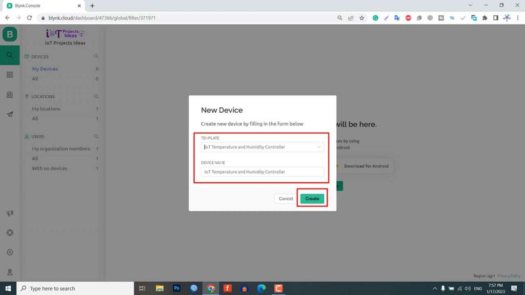
To add a new device to your Blynk dashboard, click on the search icon and then select “Add New Device.” From the options that appear, choose “From Template” and select the template you want to use. Give your device a name and click “Create.” A new device will be added to your dashboard.
You can find the code header file. You will need this in the program code. This will include the template ID, device name, and authentication token.
Source Code/Program
This is the program code for the IoT Temperature and Humidity Monitoring and control system with ESP32 and Blynk 2.0. This code is written in Arduino IDE. We need to install the following library first.
- Blynk Library (Version 1.1.0)
- DHT Sensor Library
- Adafruit SSD1306 Library
- Adafruit GFX Library
- Preferences Library
/* Fill-in your Template ID (only if using Blynk.Cloud) */
#define BLYNK_TEMPLATE_ID "xxxx-xxxx-xxxx"
#define BLYNK_DEVICE_NAME "xxxx-xxxx-xxxx"
#define BLYNK_AUTH_TOKEN "xxxx-xxxx-xxxx"

// Your WiFi credentials.
// Set password to "" for open networks.
char ssid[] = "xxxx-xxxx-xxxx";
char pass[] = "xxxx-xxxx-xxxx";


#include <WiFi.h>
#include <BlynkSimpleEsp32.h>
#include <DHT.h>
#include <Preferences.h>
#include <AceButton.h>
#include <SPI.h>
#include <Wire.h>
#include <Adafruit_GFX.h>
#include <Adafruit_SSD1306.h>

using namespace ace_button;
Preferences pref;

#define DHTPIN            23 //D23  pin connected with DHT
// Uncomment whatever type you're using!
#define DHTTYPE DHT11     // DHT 11
//#define DHTTYPE DHT22   // DHT 22, AM2302, AM2321
//#define DHTTYPE DHT21   // DHT 21, AM2301

#define SCREEN_WIDTH 128 // OLED display width, in pixels
#define SCREEN_HEIGHT 64 // OLED display height, in pixels
#define OLED_RESET     -1 // Reset pin # (or -1 if sharing Arduino reset pin)
#define SCREEN_ADDRESS 0x3C ///< See datasheet for Address; 0x3D for 128x64, 0x3C for 128x32
Adafruit_SSD1306 display(SCREEN_WIDTH, SCREEN_HEIGHT, &Wire, OLED_RESET);

// Setpoint and setHumi values (in degrees Celsius)
float setTemp = 0;
float setHumi = 0;
float currentTemp = 0;
float currentHumi = 0;


// define the GPIO connected with Relays and Buttons
#define RelayPin1 18  //D18
#define RelayPin2 19  //D19

#define ButtonPin1 25  //D25
#define ButtonPin2 26  //D26
#define ButtonPin3 27  //D27

#define wifiLed   2   //D2

//Change the virtual pins according the rooms
#define VPIN_Text           V0
#define VPIN_Mode           V1
#define VPIN_currentTemp    V2
#define VPIN_currentHumi    V3
#define VPIN_setTemp        V4
#define VPIN_setHumi        V5
#define VPIN_Heater         V6
#define VPIN_Humidifier     V7

// Relay and Mode State
bool heaterState = LOW; //Define integer to remember the toggle state for heater
bool humidifierState = LOW; //Define integer to remember the toggle state for Humidifier
bool modeState = LOW; //Define integer to remember the mode

int wifiFlag = 0;


char auth[] = BLYNK_AUTH_TOKEN;

ButtonConfig config1;
AceButton button1(&config1);
ButtonConfig config2;
AceButton button2(&config2);
ButtonConfig config3;
AceButton button3(&config3);

void handleEvent1(AceButton*, uint8_t, uint8_t);
void handleEvent2(AceButton*, uint8_t, uint8_t);
void handleEvent3(AceButton*, uint8_t, uint8_t);


BlynkTimer timer;
DHT dht(DHTPIN, DHTTYPE);

// When App button is pushed - switch the state

BLYNK_WRITE(VPIN_Heater) {
  heaterState = param.asInt();
  digitalWrite(RelayPin1, !heaterState);
  pref.putBool("Heater", heaterState);
}

BLYNK_WRITE(VPIN_Humidifier) {
  humidifierState = param.asInt();
  digitalWrite(RelayPin2, !humidifierState);
  pref.putBool("Humidifier", humidifierState);
}

BLYNK_WRITE(VPIN_Mode) {
  modeState = param.asInt();
  pref.putBool("Mode", modeState);
}

BLYNK_WRITE(VPIN_setTemp) {
  setTemp = param.asFloat();
  pref.putBool("setemp", setTemp);
}

BLYNK_WRITE(VPIN_setHumi) {
  setHumi = param.asFloat();
  pref.putBool("Humidity", setHumi);
}

void checkBlynkStatus() { // called every 2 seconds by SimpleTimer

  bool isconnected = Blynk.connected();
  if (isconnected == false) {
    wifiFlag = 1;
    Serial.println("Blynk Not Connected");
    display.setTextSize(1);
    display.setTextColor(SSD1306_WHITE);
    display.setCursor(0, 2);
    digitalWrite(wifiLed, LOW);
  }
  if (isconnected == true) {
    wifiFlag = 0;
    display.setTextSize(1);
    display.setTextColor(SSD1306_WHITE);
    display.setCursor(0, 2);
    display.println(" Blynk IoT Connected ");
    digitalWrite(wifiLed, HIGH);
    Blynk.virtualWrite(VPIN_Text, "IoT Temperature & Humidity Controller");
  }
  display.display();
  delay(1000);
}

BLYNK_CONNECTED() {
  // update the latest state to the server
  Blynk.virtualWrite(VPIN_Text, "IoT Temperature & Humidity Controller");
  Blynk.virtualWrite(VPIN_Mode, modeState);
  Blynk.syncVirtual(VPIN_currentTemp);
  Blynk.syncVirtual(VPIN_currentHumi);
  Blynk.syncVirtual(VPIN_setTemp);
  Blynk.syncVirtual(VPIN_setHumi);
  Blynk.virtualWrite(VPIN_Heater, heaterState);
  Blynk.virtualWrite(VPIN_Humidifier, humidifierState);

}

void setup()
{
  Serial.begin(115200);
  //Open namespace in read-write mode
  pref.begin("Relay_State", false);

  pinMode(RelayPin1, OUTPUT);
  pinMode(RelayPin2, OUTPUT);
  pinMode(wifiLed, OUTPUT);

  pinMode(ButtonPin1, INPUT_PULLUP);
  pinMode(ButtonPin2, INPUT_PULLUP);
  pinMode(ButtonPin3, INPUT_PULLUP);

  // SSD1306_SWITCHCAPVCC = generate display voltage from 3.3V internally
  if (!display.begin(SSD1306_SWITCHCAPVCC, SCREEN_ADDRESS)) {
    Serial.println(F("SSD1306 allocation failed"));
    for (;;); // Don't proceed, loop forever
  }
  display.clearDisplay();
  display.setTextColor(SSD1306_WHITE);
  display.display();

  //During Starting all Relays should TURN OFF
  digitalWrite(RelayPin1, !heaterState);
  digitalWrite(RelayPin2, !humidifierState);

  dht.begin();    // Enabling DHT sensor
  digitalWrite(wifiLed, LOW);

  config1.setEventHandler(button1Handler);
  config2.setEventHandler(button2Handler);
  config3.setEventHandler(button3Handler);

  button1.init(ButtonPin1);
  button2.init(ButtonPin2);
  button3.init(ButtonPin3);

  //Blynk.begin(auth, ssid, pass);
  WiFi.begin(ssid, pass);
  timer.setInterval(2000L, checkBlynkStatus); // check if Blynk server is connected every 2 seconds
  timer.setInterval(1000L, sendSensor); // Sending Sensor Data to Blynk Cloud every 1 second
  Blynk.config(auth);
  delay(1000);

  getRelayState(); // Get the last state of Relays and Set values of Temp & Humidity

  Blynk.virtualWrite(VPIN_Heater, heaterState);
  Blynk.virtualWrite(VPIN_Humidifier, humidifierState);
  Blynk.virtualWrite(VPIN_setTemp, setTemp);
  Blynk.virtualWrite(VPIN_setHumi, setHumi);
}


void readSensor() {

  currentTemp = dht.readTemperature();
  currentHumi = dht.readHumidity();
  if (isnan(currentHumi) || isnan(currentTemp)) {
    Serial.println("Failed to read from DHT sensor!");
    return;
  }
}

void sendSensor()
{
  readSensor();
  // You can send any value at any time.
  // Please don't send more that 10 values per second.
  Blynk.virtualWrite(VPIN_Text, "IoT Temperature & Humidity Controller");
  Blynk.virtualWrite(VPIN_currentTemp, currentTemp);
  Blynk.virtualWrite(VPIN_currentHumi, currentHumi);
}

void getRelayState()
{
  //Serial.println("reading data from NVS");
  modeState = pref.getBool("Mode", 0);
  Blynk.virtualWrite(VPIN_Mode, modeState);
  delay(200);
  heaterState = pref.getBool("Heater", 0);
  digitalWrite(RelayPin1, !heaterState);
  Blynk.virtualWrite(VPIN_Heater, heaterState);
  delay(200);
  humidifierState = pref.getBool("Humidifier", 0);
  digitalWrite(RelayPin2, !humidifierState);
  Blynk.virtualWrite(VPIN_Humidifier, humidifierState);
  delay(200);
  setTemp = pref.getBool("setemp", 0);
  Blynk.virtualWrite(VPIN_setTemp, setTemp);
  delay(200);
  setHumi = pref.getBool("Humidity", 0);
  Blynk.virtualWrite(VPIN_setHumi, setHumi);
  delay(200);
}


void DisplayData()  {
  display.clearDisplay();
  display.setTextSize(2);
  display.setCursor(0, 7);
  display.println("----------");
  display.setCursor(2, 20);
  display.print(int(currentTemp));
  display.print((char)247);
  display.println("C");
  display.setCursor(60, 20);
  display.print(": ");
  display.print(int(currentHumi));
  display.println("%");
  display.setCursor(0, 34);
  display.println("----------");

  display.setTextSize(1);
  display.setCursor(0, 57);
  display.print("sTemp:");
  display.print(int(setTemp));
  display.print((char)247);
  display.println("C");
  display.setTextSize(1);
  display.setCursor(67, 57);
  display.print("sHumi:");
  display.print(int(setHumi));
  display.println("%");


  if (modeState == 1) {
    display.setTextSize(1);
    display.setCursor(20, 45);
    display.print("Automatic Mode");
    if (currentTemp < setTemp) {
      heaterState = 1;
      digitalWrite(RelayPin1, !heaterState);
      pref.putBool("Heater", heaterState);
      Serial.println("Heater ON");
      Blynk.virtualWrite(VPIN_Heater, heaterState);
    } else {
      heaterState = 0;
      digitalWrite(RelayPin1, !heaterState);
      pref.putBool("Heater", heaterState);
      Serial.println("Heater OFF");
      Blynk.virtualWrite(VPIN_Heater, heaterState);
    } if (currentHumi < setHumi) {
      humidifierState = 1;
      digitalWrite(RelayPin2, !humidifierState);
      Serial.println("Humidifier ON");
      pref.putBool("Humidifier", humidifierState);
      Blynk.virtualWrite(VPIN_Humidifier, humidifierState);
    } else {
      humidifierState = 0;
      digitalWrite(RelayPin2, !humidifierState);
      Serial.println("Humidifier OFF");
      pref.putBool("Humidifier", humidifierState);
      Blynk.virtualWrite(VPIN_Humidifier, humidifierState);
    }
  } else {
    display.setTextSize(1);
    display.setCursor(32, 45);
    display.print("Manual Mode");
  }
  display.display();
}


void loop()
{
  Blynk.run();
  timer.run();
  DisplayData();
  button1.check();
  button2.check();
  button3.check();
}

void button1Handler(AceButton* button, uint8_t eventType, uint8_t buttonState) {
  Serial.println("Mode");
  switch (eventType) {
    case AceButton::kEventReleased:
      modeState = !modeState;
      pref.putBool("Mode", modeState);
      Blynk.virtualWrite(VPIN_Mode, modeState);
      break;
  }
}
void button2Handler(AceButton* button, uint8_t eventType, uint8_t buttonState) {
  Serial.println("Heater");
  switch (eventType) {
    case AceButton::kEventReleased:
      digitalWrite(RelayPin1, heaterState);
      heaterState = !heaterState;
      pref.putBool("Heater", heaterState);
      Blynk.virtualWrite(VPIN_Heater, heaterState);
      break;
  }
}
void button3Handler(AceButton* button, uint8_t eventType, uint8_t buttonState) {
  Serial.println("Humidifier");
  switch (eventType) {
    case AceButton::kEventReleased:
      digitalWrite(RelayPin2, humidifierState);
      humidifierState = !humidifierState;
      pref.putBool("VPIN_Humidifier", humidifierState);
      Blynk.virtualWrite(VPIN_Humidifier, humidifierState);
      break;
  }
}
Now you can paste the Template ID, Device Name, and Authentication token to the program code in the following lines.
/* Fill-in your Template ID (only if using Blynk.Cloud) */
#define BLYNK_TEMPLATE_ID "xxxx-xxxx-xxxx"
#define BLYNK_DEVICE_NAME "xxxx-xxxx-xxxx"
#define BLYNK_AUTH_TOKEN "xxxx-xxxx-xxxx"
Update your WiFi SSID and Password from this line of code.
// Your WiFi credentials.
// Set password to "" for open networks.
char ssid[] = "xxxx-xxxx-xxxx";
char pass[] = "xxxx-xxxx-xxxx";
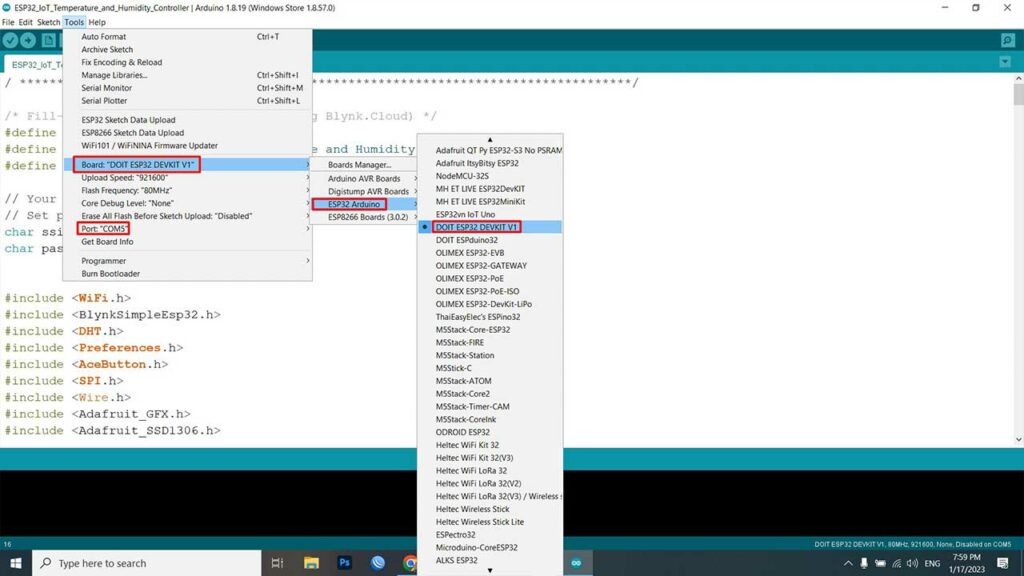
To upload the program code: Select the ESP32 Devkit V1 board and the correct COM port from the Tools menu. Click the “upload” button to upload the code.
The code will take some time to compile. After compilation is complete press the boot button on ESP32 for a few seconds. Then the upload process will be started.
Once the code is uploaded, the device is ready for testing. The ESP32 will try to connect to the WiFi network. Once it is connected, it will connect to the Blynk platform using the Blynk authentication token.
At the same time, the 0.96-inch OLED display will show the Blynk IoT connection status, the current temperature in degrees Celsius, the humidity in percentage, the device operating mode, the set temperature, and the set humidity.
Source Code/Program Explanation
Definitely, here is a more detailed explanation of the program code:
Connect to the Blynk platform with WiFi
The program begins by defining several constants and variables:
BLYNK_TEMPLATE_ID: This is the template ID for the project. BLYNK_DEVICE_NAME: This is the name of the device that the program is running on. BLYNK_AUTH_TOKEN: This is the authorization token that the device uses to authenticate with the Blynk server. ssid and pass: These are the WiFi network’s SSID and password.
/* Fill-in your Template ID (only if using Blynk.Cloud) */
#define BLYNK_TEMPLATE_ID "xxxx-xxxx-xxxx"
#define BLYNK_DEVICE_NAME "xxxx-xxxx-xxxx"
#define BLYNK_AUTH_TOKEN "xxxx-xxxx-xxxx"

// Your WiFi credentials.
// Set password to "" for open networks.
char ssid[] = "xxxx-xxxx-xxxx";
char pass[] = "xxxx-xxxx-xxxx";
Including Libraries
The program then includes several libraries:
- WiFi.h: This library allows the program to connect to a WiFi network.
- BlynkSimpleEsp32.h: This library allows the program to connect to the Blynk cloud service and communicate with the Blynk app.
- DHT.h: This library allows the program to read data from a DHT11 temperature and humidity sensor.
- Preferences.h: This library allows the program to store persistent data (i.e. data that will be retained even if the device is powered off).
- AceButton.h: This library allows the program to use buttons and define button press events.
- Wire.h: This library allows the program to communicate with the OLED screen.
- Adafruit_GFX.h and Adafruit_SSD1306.h: These libraries allow the program to control the OLED screen.
#include <WiFi.h>
#include <BlynkSimpleEsp32.h>
#include <DHT.h>
#include <Preferences.h>
#include <AceButton.h>
#include <Wire.h>
#include <Adafruit_GFX.h>
#include <Adafruit_SSD1306.h>
Constants and Variables
This program code defines several constants and variables related to the OLED screen:
- SCREEN_WIDTH and SCREEN_HEIGHT: These constants define the width and height of the OLED screen in pixels.
- OLED_RESET: This constant defines the reset pin for the OLED screen.
- SCREEN_ADDRESS: This constant defines the I2C address of the OLED screen.
#define SCREEN_WIDTH 128 // OLED display width, in pixels
#define SCREEN_HEIGHT 64 // OLED display height, in pixels
#define OLED_RESET     -1 // Reset pin # (or -1 if sharing Arduino reset pin)
#define SCREEN_ADDRESS 0x3C ///< See datasheet for Address; 0x3D for 128x64, 0x3C for 128x32
Adafruit_SSD1306 display(SCREEN_WIDTH, SCREEN_HEIGHT, &Wire, OLED_RESET);
The program also defines several constants and variables related to the heating and humidifying system:
- DHTPIN: This constant defines the pin that the DHT11 sensor is connected to.
- DHTTYPE: This constant defines the type of DHT sensor being used (e.g. DHT11, DHT22).
- RelayPin1 and RelayPin2: These constants define the pins that the heating and humidifying devices are connected to.
- ButtonPin1, ButtonPin2, and ButtonPin3: These constants define the pins that the buttons are connected to.
- wifiLed: This constant defines the pin that the WiFi status LED is connected to.
- VPIN_Text, VPIN_Mode, VPIN_currentTemp, VPIN_currentHumi, VPIN_setTemp, VPIN_setHumi, VPIN_Heater, and VPIN_Humidifier: These constants define the virtual pins (i.e. pins that exist within the Blynk app) that are used to communicate with the Blynk app.
#define DHTPIN            23 //D23  pin connected with DHT
// Uncomment whatever type you're using!
#define DHTTYPE DHT11     // DHT 11
//#define DHTTYPE DHT22   // DHT 22, AM2302, AM2321
//#define DHTTYPE DHT21   // DHT 21, AM2301
// define the GPIO connected with Relays and Buttons
#define RelayPin1 18  //D18
#define RelayPin2 19  //D19

#define ButtonPin1 25  //D25
#define ButtonPin2 26  //D26
#define ButtonPin3 27  //D27

#define wifiLed   2   //D2

//Change the virtual pins according the rooms
#define VPIN_Text           V0
#define VPIN_Mode           V1
#define VPIN_currentTemp    V2
#define VPIN_currentHumi    V3
#define VPIN_setTemp        V4
#define VPIN_setHumi        V5
#define VPIN_Heater         V6
#define VPIN_Humidifier     V7
The program also defines several variables to store the current and target temperature and humidity levels, as well as the current states of the heating, humidifying, and mode.
- setTemp and setHumi: These variables store the target temperature and humidity levels, respectively.
- currentTemp and currentHumi: These variables store the current temperature and humidity levels, respectively.
- heaterState and humidifierState: These variables store the current state of the heating and humidifying devices, respectively (i.e. whether they are on or off).
- modeState: This variable stores the current mode of the system (i.e. heating, humidifying, or off).
float setTemp = 0;
float setHumi = 0;
float currentTemp = 0;
float currentHumi = 0;
ool heaterState = LOW;
bool humidifierState = LOW;
bool modeState = LOW;
Defining different Objects
The program then defines several objects:
- pref: This object is an instance of the Preferences library, which allows the program to store persistent data.
- display: This object is an instance of the Adafruit_SSD1306 class, which allows the program to control the OLED screen.
- timer: This object is an instance of the BlynkTimer class, which allows the program to schedule tasks to run at specific intervals.
- dht: This object is an instance of the DHT class, which allows the program to read data from the DHT11 sensor.
Callback Functions for Buttons
The program then defines three callback functions for the buttons:
- handleEvent1: This function is called when the first button is pressed.
- handleEvent2: This function is called when the second button is pressed.
- handleEvent3: This function is called when the third button is pressed.
void handleEvent1(AceButton*, uint8_t, uint8_t);
void handleEvent2(AceButton*, uint8_t, uint8_t);
void handleEvent3(AceButton*, uint8_t, uint8_t);

void button1Handler(AceButton* button, uint8_t eventType, uint8_t buttonState) {
  Serial.println("Mode");
  switch (eventType) {
    case AceButton::kEventReleased:
      modeState = !modeState;
      pref.putBool("Mode", modeState);
      Blynk.virtualWrite(VPIN_Mode, modeState);
      break;
  }
}
void button2Handler(AceButton* button, uint8_t eventType, uint8_t buttonState) {
  Serial.println("Heater");
  switch (eventType) {
    case AceButton::kEventReleased:
      digitalWrite(RelayPin1, heaterState);
      heaterState = !heaterState;
      pref.putBool("Heater", heaterState);
      Blynk.virtualWrite(VPIN_Heater, heaterState);
      break;
  }
}
void button3Handler(AceButton* button, uint8_t eventType, uint8_t buttonState) {
  Serial.println("Humidifier");
  switch (eventType) {
    case AceButton::kEventReleased:
      digitalWrite(RelayPin2, humidifierState);
      humidifierState = !humidifierState;
      pref.putBool("VPIN_Humidifier", humidifierState);
      Blynk.virtualWrite(VPIN_Humidifier, humidifierState);
      break;
  }
}
BLYNK_WRITE Function
This program code then defines several Blynk write event handlers:
- BLYNK_WRITE(VPIN_Heater): This function is called when the user toggles the heater on or off in the Blynk app. It updates the heater state and writes the new state to the relay pin. It also stores the new state in persistent storage.
- BLYNK_WRITE(VPIN_Humidifier): This function is called when the user toggles the humidifier on or off in the Blynk app. It updates the humidifier state and writes the new state to the relay pin. It also stores the new state in persistent storage.
- BLYNK_WRITE(VPIN_Mode): This function is called when the user toggles the mode in the Blynk app. It updates the mode state and stores the new state in persistent storage.
- BLYNK_WRITE(VPIN_setTemp): This function is called when the user updates the target temperature in the Blynk app. It updates the target temperature and stores the new value in persistent storage.
- BLYNK_WRITE(VPIN_setHumi): This function is called when the user updates the target humidity in the Blynk app. It updates the target humidity and stores the new value in persistent storage.
BLYNK_WRITE(VPIN_Heater) {
  heaterState = param.asInt();
  digitalWrite(RelayPin1, !heaterState);
  pref.putBool("Heater", heaterState);
}

BLYNK_WRITE(VPIN_Humidifier) {
  humidifierState = param.asInt();
  digitalWrite(RelayPin2, !humidifierState);
  pref.putBool("Humidifier", humidifierState);
}

BLYNK_WRITE(VPIN_Mode) {
  modeState = param.asInt();
  pref.putBool("Mode", modeState);
}

BLYNK_WRITE(VPIN_setTemp) {
  setTemp = param.asFloat();
  pref.putBool("setemp", setTemp);
}

BLYNK_WRITE(VPIN_setHumi) {
  setHumi = param.asFloat();
  pref.putBool("Humidity", setHumi);
}
Void DisplayData Function
The program then defines a function called displayData that displays the current and target temperature and humidity values on the OLED screen.
- Basically, If the current temperature is less than the target temperature, it turns on the heater by setting the heaterState variable to high and writing the value to the relay pin.
- Whenever the current temperature is greater than or equal to the target temperature, it turns off the heater by setting the heaterState variable to low and writing the value to the relay pin.
- When the current humidity is less than the target humidity, it turns on the humidifier by setting the humidifierState variable to high and writing the value to the relay pin.
- If the current humidity is greater than or equal to the target humidity, it turns off the humidifier by setting the humidifierState variable to low and writing the value to the relay pin.
- Then finally, Calls the Blynk.virtualWrite function to send the current temperature, humidity, heater state, and humidifier state to the Blynk app.
void DisplayData()  {
  display.clearDisplay();
  display.setTextSize(2);
  display.setCursor(0, 7);
  display.println("----------");
  display.setCursor(2, 20);
  display.print(int(currentTemp));
  display.print((char)247);
  display.println("C");
  display.setCursor(60, 20);
  display.print(": ");
  display.print(int(currentHumi));
  display.println("%");
  display.setCursor(0, 34);
  display.println("----------");

  display.setTextSize(1);
  display.setCursor(0, 57);
  display.print("sTemp:");
  display.print(int(setTemp));
  display.print((char)247);
  display.println("C");
  display.setTextSize(1);
  display.setCursor(67, 57);
  display.print("sHumi:");
  display.print(int(setHumi));
  display.println("%");


  if (modeState == 1) {
    display.setTextSize(1);
    display.setCursor(20, 45);
    display.print("Automatic Mode");
    if (currentTemp < setTemp) {
      heaterState = 1;
      digitalWrite(RelayPin1, !heaterState);
      pref.putBool("Heater", heaterState);
      Serial.println("Heater ON");
      Blynk.virtualWrite(VPIN_Heater, heaterState);
    } else {
      heaterState = 0;
      digitalWrite(RelayPin1, !heaterState);
      pref.putBool("Heater", heaterState);
      Serial.println("Heater OFF");
      Blynk.virtualWrite(VPIN_Heater, heaterState);
    } if (currentHumi < setHumi) {
      humidifierState = 1;
      digitalWrite(RelayPin2, !humidifierState);
      Serial.println("Humidifier ON");
      pref.putBool("Humidifier", humidifierState);
      Blynk.virtualWrite(VPIN_Humidifier, humidifierState);
    } else {
      humidifierState = 0;
      digitalWrite(RelayPin2, !humidifierState);
      Serial.println("Humidifier OFF");
      pref.putBool("Humidifier", humidifierState);
      Blynk.virtualWrite(VPIN_Humidifier, humidifierState);
    }
  } else {
    display.setTextSize(1);
    display.setCursor(32, 45);
    display.print("Manual Mode");
  }
  display.display();
}
Void Setup Function
The program then defines the setup function, which runs once when the device is powered on or reset. The setup function does the following:
- Initializes the OLED screen.
- Initializes the buttons and assigns each button a callback function.
- Initializes the DHT11 sensor.
- Initializes the relay pins and sets them to low.
- Initializes the WiFi LED pin and sets it to low.
- Connects to the WiFi network using the WiFi.begin function.
- Connects to the Blynk cloud service using the Blynk.begin function and the BLYNK_AUTH_TOKEN.
- Reads the EEPROM storage to retrieve the previously saved values for the heater and humidifier states, mode state, and target temperature and humidity levels.
- Sets the relay pins and WiFi LED pin to the values retrieved from EEPROM.
- Schedules the displayData function to run every 1000 milliseconds (i.e. 1 second) using the timer.setInterval function.
void setup()
{
  Serial.begin(115200);
  //Open namespace in read-write mode
  pref.begin("Relay_State", false);

  pinMode(RelayPin1, OUTPUT);
  pinMode(RelayPin2, OUTPUT);
  pinMode(wifiLed, OUTPUT);

  pinMode(ButtonPin1, INPUT_PULLUP);
  pinMode(ButtonPin2, INPUT_PULLUP);
  pinMode(ButtonPin3, INPUT_PULLUP);

  // SSD1306_SWITCHCAPVCC = generate display voltage from 3.3V internally
  if (!display.begin(SSD1306_SWITCHCAPVCC, SCREEN_ADDRESS)) {
    Serial.println(F("SSD1306 allocation failed"));
    for (;;); // Don't proceed, loop forever
  }
  display.clearDisplay();
  display.setTextColor(SSD1306_WHITE);
  display.display();

  //During Starting all Relays should TURN OFF
  digitalWrite(RelayPin1, !heaterState);
  digitalWrite(RelayPin2, !humidifierState);

  dht.begin();    // Enabling DHT sensor
  digitalWrite(wifiLed, LOW);

  config1.setEventHandler(button1Handler);
  config2.setEventHandler(button2Handler);
  config3.setEventHandler(button3Handler);

  button1.init(ButtonPin1);
  button2.init(ButtonPin2);
  button3.init(ButtonPin3);

  //Blynk.begin(auth, ssid, pass);
  WiFi.begin(ssid, pass);
  timer.setInterval(2000L, checkBlynkStatus); // check if Blynk server is connected every 2 seconds
  timer.setInterval(1000L, sendSensor); // Sending Sensor Data to Blynk Cloud every 1 second
  Blynk.config(auth);
  delay(1000);

  getRelayState(); // Get the last state of Relays and Set values of Temp & Humidity

  Blynk.virtualWrite(VPIN_Heater, heaterState);
  Blynk.virtualWrite(VPIN_Humidifier, humidifierState);
  Blynk.virtualWrite(VPIN_setTemp, setTemp);
  Blynk.virtualWrite(VPIN_setHumi, setHumi);
}
Void Loop Function
The program then defines the loop function, which runs continuously after the setup function completes. The loop function does the following:
- Calls the Blynk.run function to process any incoming Blynk messages.
- Calls the dht.readTemperature and dht.readHumidity functions to read the current temperature and humidity levels from the DHT11 sensor.
- Calls the displayData function to display the current and target temperature and humidity values on the OLED screen.
- Calls the button1.check(), button2.check(), and button3.check() functions to process any button press events. It also calls the Blynk.virtualWrite function to send the current temperature, humidity, heater state, and humidifier state to the Blynk app.
void loop()
{
  Blynk.run();
  timer.run();
  DisplayData();
  button1.check();
  button2.check();
  button3.check();
}
Blynk IoT Mobile App Dashboard
Now let’s set up the blynk IoT dashboard for mobile phones. First, Download the blynk application into your mobile.
- New Blynk Mobile App (Android)
- New Blynk Mobile App (iOS)
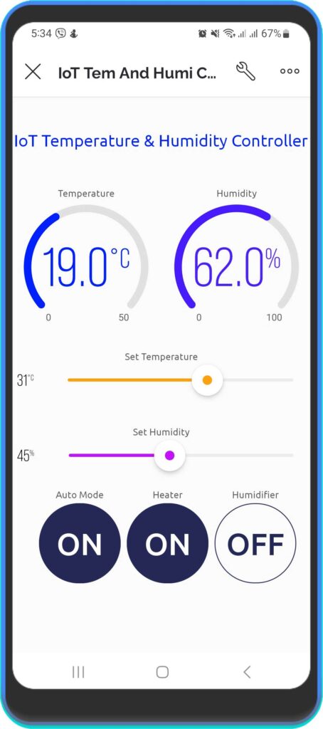
After installing the application login into your account. You will see a new device “IoT Temperature & Humidity Controller” Click on it and start configuring the mobile dashboard. As done on the web dashboard I have used one Label widget, two gauge widgets, two slider widgets, and three button widgets.
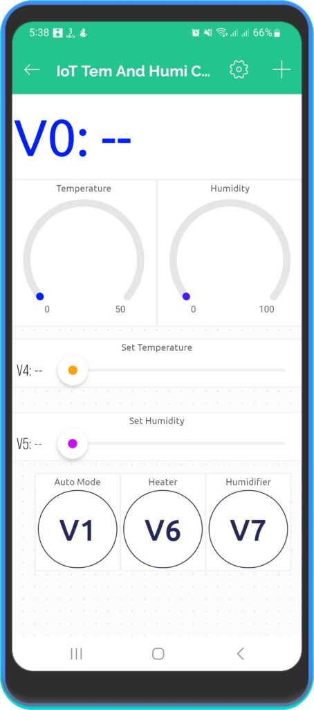
See this screenshot for the configuration and setup of each widget used in this project.
So, that’s all for the Mobile dashboard setup.
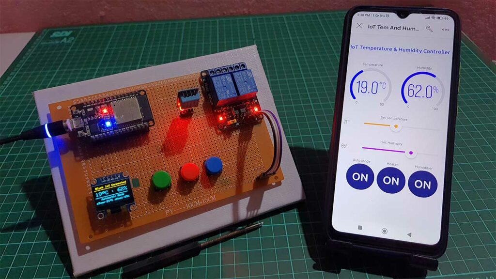
Now you can see the data of your blynk device in your mobile app and in the web dashboard as well.
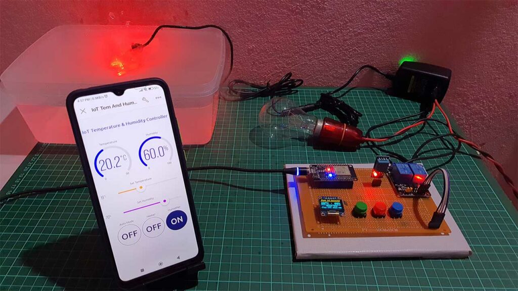
Testing: IoT Temperature & Humidity Monitoring & Control System with ESP32 & Blynk
Once the code is uploaded, the device is ready for testing. The ESP32 will try to connect to the WiFi network. Once it is connected, it will connect to the Blynk platform using the Blynk authentication token.
At the same time, the 0.96-inch OLED display will show the Blynk IoT connection status, the current temperature in degrees Celsius, the humidity in percentage, the device operating mode, the set temperature, and the set humidity.
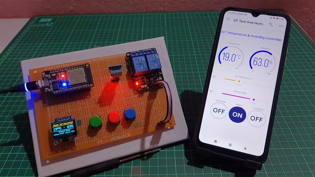
Furthermore, the same data can also be viewed from the Blynk IoT app or the Blynk web dashboard from any location in the world.
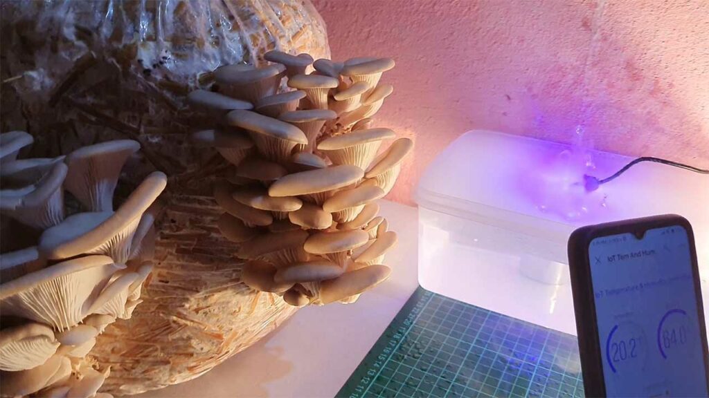
I have already discussed the useful features of this device. Now let’s see how this system helps to grow mushrooms in low-temperature conditions.
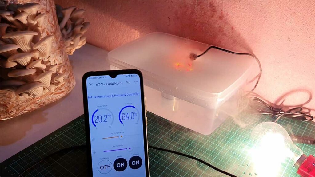
It is very important to maintain the optimal temperature and humidity levels for growing mushrooms, as these conditions can greatly affect the success of the cultivation process. By using this IoT-based temperature and humidity control system, you can easily monitor and regulate the conditions in your mushroom grow room, ensuring that your mushrooms have the best chance of growing and thriving. With the ability to remotely monitor and control the conditions in your grow room, you can fine-tune the temperature and humidity levels to meet the specific needs of your mushroom variety, even in low-temperature environments.
Video tutorial & Guide
Conclusion
Certainly, By following the steps outlined in this tutorial, you can learn how to set up and use an IoT-based temperature and humidity control system to grow your own mushrooms at home. If you have any other questions, you can leave a comment in the comments section below.


Dear Sir/Madam:
This is an interesting and wonderful IoT Automation Project using ESP32 & Blynk 2.0. I wonder if you could send me the main program code such that I could physically facilitate on my Arduino IDE,
Thank you so much & have a nice day.
Truly,
Kent Horng
Hi
Great project going to use it as a basis for my project
Got it up and running but keeps disconnecting
Any ideas?
Many thanks
Peter
Hi,
This was a great IoT project which i had seen. I was eager to work on this project base in my college project but am not able to process this out as you done. am stuck somewhere like my misting and display is not working as well am unable to see any progress in my Blynk IoT. can you please help me in this.
what is the connection here…i mean can it be viewed from anywhere in the world and how did you accomplish that because i didn’t see any router to connect the esp8266 please i need more info
the code is running fine and it show results on oled display but it is not getting connected to wifi and blynk IoT. please reply as soon as possible
KARTI RESETLEDİĞİMİZDE TEKRARDAN BAĞNAMIYOR