Temperature Control with ESP8266 & AsyncWebServer
ESP8266 based Thermostat Controller with AsyncWebServer
The temperature control system has a wide range of applications, from HVAC (Heating, Ventilation, and Air Conditioning) systems to industrial processes. In this tutorial, we will demonstrate how to build a temperature control system using an ESP8266 microcontroller, DS18B20 temperature sensor, and an OLED display. We will also use the ESPDash Library with AsyncWebServer library to set up a web server that allows the temperature control system to be controlled and monitored remotely through a web interface.
- Overview: Temperature Control with ESP8266
- Components Required
- Features: ESP8266 Temperature Controller
- Interfacing DS18B20, OLED, & Relay With ESP8266
- Project PCB Gerber File & PCB Ordering Online
- Program Code
- Program Code Explanation
- Uploading Code & Testing Temperature Controller using ESP8266
- Conclusion
This tutorial will guide you through the steps of setting up the hardware, installing the necessary libraries, and writing the code to implement the temperature control system. By the end of this tutorial, you will have a working temperature control system that you can customize to meet your specific needs.
Overview: Temperature Control with ESP8266
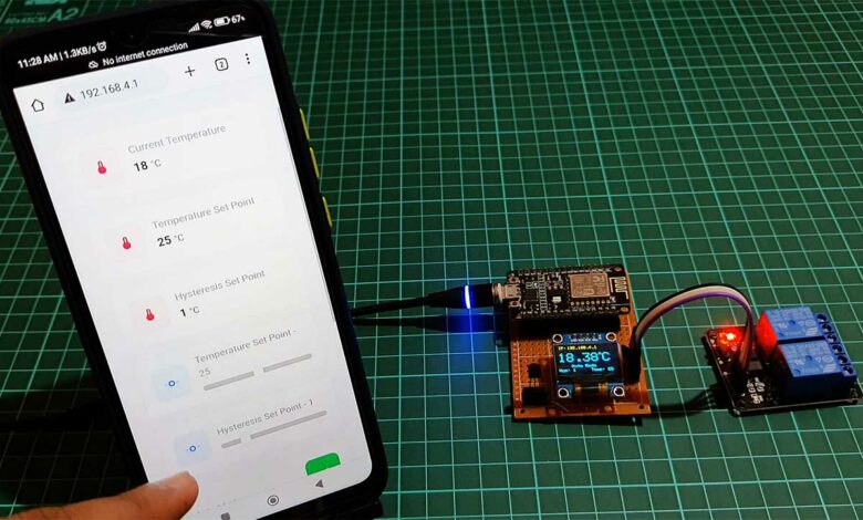
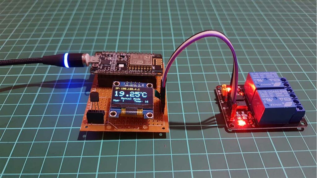
The ESP8266 microcontroller reads the temperature from a DS18B20 temperature sensor and displays it on an OLED display. It then uses this temperature to control heating and cooling relays in either automatic or manual mode. The set point and hysteresis values can be adjusted remotely through a web interface. In automatic mode, the program turns on the heating relay if the temperature is below the set point minus the hysteresis value, or the cooling relay if the temperature is above the set point plus the hysteresis value. In manual mode, the program turns on the heating or cooling relays based on dashboard buttons.
Components Required
First, let’s gather the materials that we will need for this Temperature Controller project. You can easily purchase them from the Amazon link provided below:
| S.N | Components Name | Quantity | |
|---|---|---|---|
| 1 | NodeMCU ESP8266 | 1 | https://amzn.to/3WaECc2 |
| 2 | DS18B20 Temperature Sensor | 1 | https://amzn.to/3WLCJm5 |
| 3 | 0.96" I2C OLED Display | 1 | https://amzn.to/3EV50PS |
| 4 | 5V 2-Channel Relay | 1 | https://amzn.to/3C6v363 |
| 5 | Jumper Cables | 10 | https://amzn.to/3YU0c6t |
| 6 | Zero PCB board | 1 | https://amzn.to/3UmLt0B |
Now that we have all of the materials that we need, let’s explore some useful features of Temperature Control with ESP8266 project.
Features: ESP8266 Temperature Controller
This temperature control system has several features that make it useful and versatile:
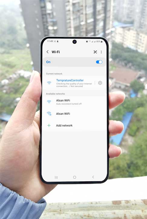
ESP8266 in SoftAP Mode
In SoftAP mode, the ESP8266 creates its own wireless network and broadcasts its own WiFi signal. Other devices, such as smartphones or laptops, can connect to this wireless network and access the webserver remotely on multiple devices. Here internet connectivity is not required for controlling this device.
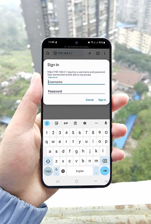
User Authentication
The Web Dashboard is secured with user authentication. A username and password are required in order to access the dashboard. If you keep your ESP8266 in SoftAP mode and set a username and password for the dashboard, only those who know the correct credentials will be able to access the dashboard. Anyone who connects to the wireless network will not be able to access the dashboard without entering the correct username and password.
Remote control and monitoring
The ESPDash and AsyncWebServer libraries are used to set up a web server that allows the temperature control system to be controlled and monitored remotely through a web interface. This allows the user to access and control the system without an active internet connection.
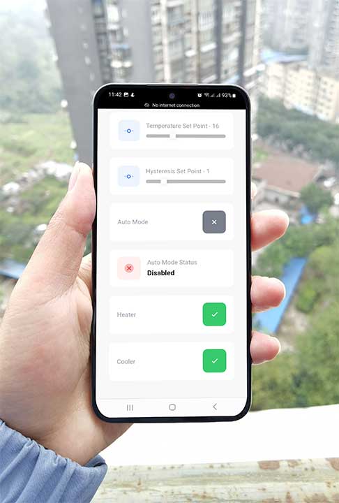
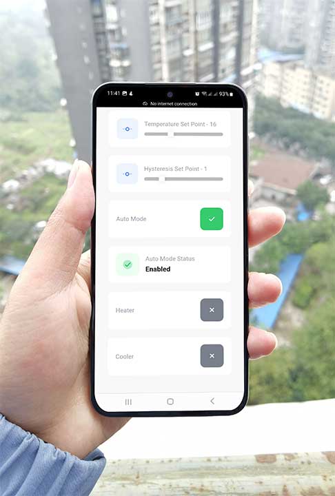
Control Modes
The system has two control modes: automatic and manual. In automatic mode, the system adjusts the heating and cooling relays based on the current temperature, set point, and hysteresis values. In manual mode, the user can manually turn on the heating or cooling relays using the corresponding buttons on the dashboard.
Temperature Set Point & Hysteresis values
The system allows the user to set a temperature set point and a hysteresis value, which determines the range around the set point within which the temperature will be maintained. The hysteresis value helps to prevent frequent switching of the heating and cooling relays, which can be noisy and wasteful of energy.
OLED display
The system includes an OLED display that displays the current temperature and other relevant information, such as the IP Address for accessing the web dashboard, control mode, and current temperature set point and hysteresis.
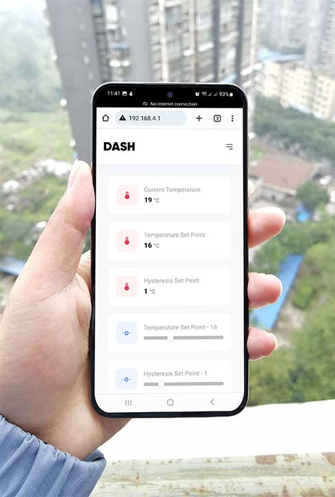
Web Dashboard
The system includes a dashboard that displays various parameters and allows the user to control and adjust them. The dashboard includes cards for displaying and controlling the current temperature, temperature set point, hysteresis set point, control mode, and the status of the heating and cooling relays.
Compatibility with ESP8266 & ESP32
The system is designed to be compatible with both the ESP8266 and ESP32 microcontrollers, allowing the user to choose the one that best meets their needs. But, if you are using ESP32 then you need to change the ESP32 pin number configuration on the program code.
/* ESP8266 Dependencies */
#include <ESP8266WiFi.h>
#include <ESPAsyncTCP.h>
#include <ESPAsyncWebServer.h>
#elif defined(ESP32)
/* ESP32 Dependencies */
#include <WiFi.h>
#include <AsyncTCP.h>
#include <ESPAsyncWebServer.h>
#endif
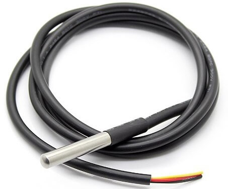
DS18B20 OneWire temperature sensor
The system uses a DS18B20 OneWire temperature sensor, which is a low-cost, digital temperature sensor that uses a single wire to communicate with the microcontroller. OneWire temperature sensors are easy to use and offer a high level of accuracy.
Relays for Heating & Cooling
The system includes 2 Channel relay module for heating and cooling. The relay module can be controlled by the microcontroller to heat up or cool down the environment as needed. The relays can be connected to a variety of heating and cooling devices, such as electric heaters, air conditioners, and fans.
Customization
The system can be easily customized to meet the specific needs of the user. For example, the set point and hysteresis values can be adjusted to achieve the desired temperature range, and the heating and cooling relays can be connected to the devices that the user wants to use to heat up or cool down the environment.
Overall, this temperature control system is a versatile and easy-to-use solution for maintaining the temperature within a certain range around a set point. It has a wide range of applications. Now you know features and collected reacquired materials. let’s start by setting up the hardware.
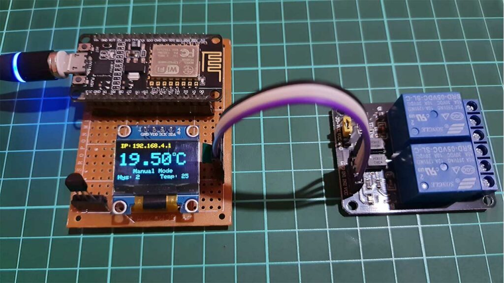
Interfacing DS18B20, OLED, & Relay With ESP8266
This is the circuit diagram of Temperature Control with ESP8266 & AsyncWebServer using DS18B20 Sensor.
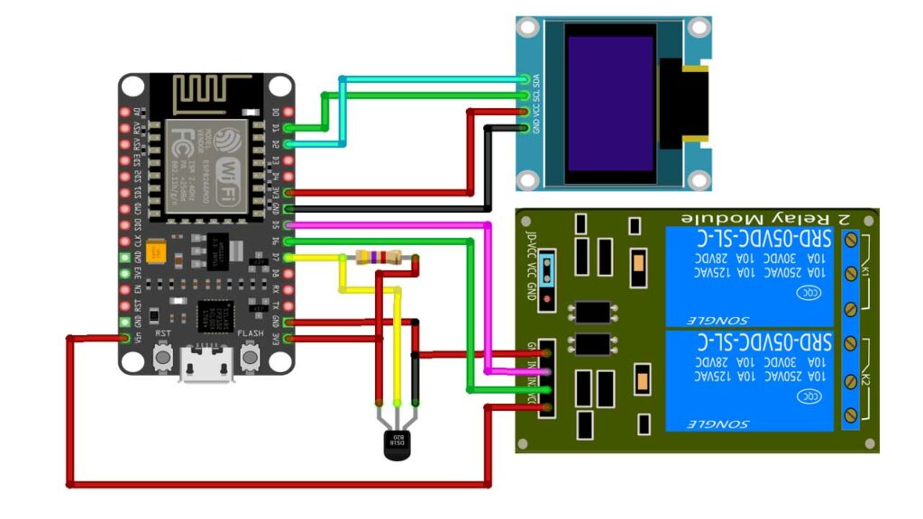
First, connect the OLED display to the ESP8266 using I2C (SCL & SDA) pins. The OLED display is powered using the 3.3V supply from the ESP8266 module, and its ground is connected to the ground of the ESP8266.
Next, connect the DS18B20 Dallas temperature sensor to the ESP8266 D7 pin. Add a 4.7k ohm resistor to D7 pin and 3.3V pin. VDD and GND pins are connected to the 3.3V supply and the ground of the ESP8266 module.
Then, connect the heating and cooling relays to the ESP8266 D5 and D6 pins. While VCC is connected to the Vin pin and GND to the Ground pin of the ESP8266 Module. Now we have set up our hardware. Let’s move on to the programming part.
Project PCB Gerber File & PCB Ordering Online
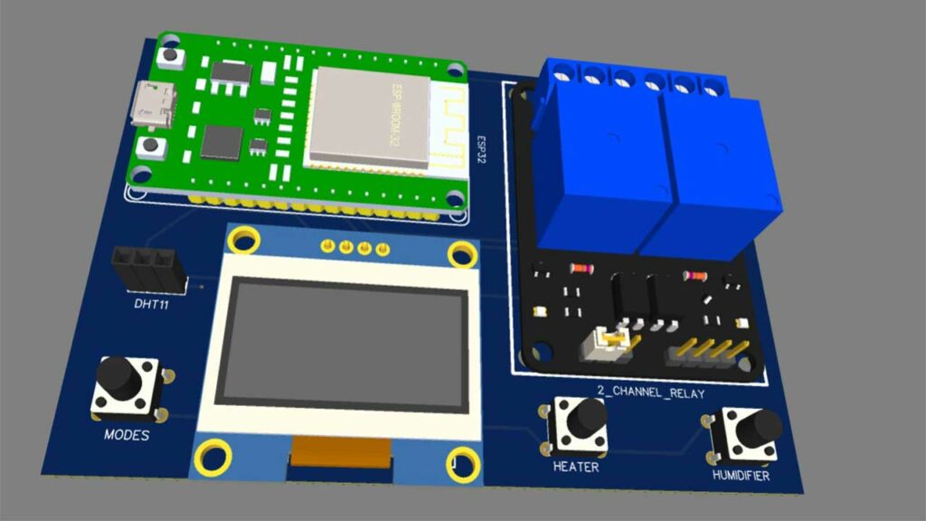
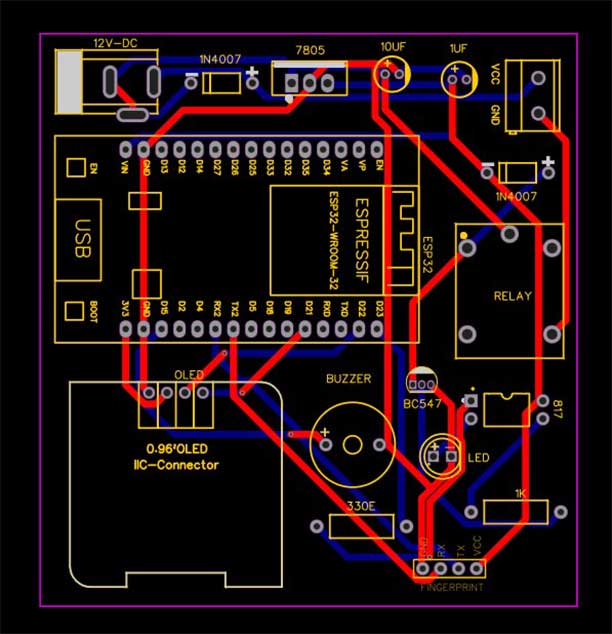
If you don’t want to assemble the circuit on a zero PCB and you want PCB for the project, then here is the PCB for you. The PCB Board for this project looks something like below.
The Gerber File for the PCB is given below. You can simply download the Gerber File and order the PCB from PCBWay.com.
PCBWay Christmas Big Sales is going on, please visit the link provided to get extra discounts and offers.
https://www.pcbway.com/activity/christmas2023.html
Now you can visit the PCBWay official website by clicking here: PCBWay.com. So you will be directed to the PCBWay website.

You can now upload the Gerber File to the Website and place an order. The PCB quality is superb & high standard. That is why most people trust PCBWay for PCB & PCBA Services.
Now, you can assemble the components on the PCB Board.
Program Code
This is the final program/source code for Temperature Control with ESP8266 & AsyncWebServer.
#include <Arduino.h>
#if defined(ESP8266)
/* ESP8266 Dependencies */
#include <ESP8266WiFi.h>
#include <ESPAsyncTCP.h>
#include <ESPAsyncWebServer.h>
#elif defined(ESP32)
/* ESP32 Dependencies */
#include <WiFi.h>
#include <AsyncTCP.h>
#include <ESPAsyncWebServer.h>
#endif
#include <ESPDash.h>
#include <OneWire.h>
#include <DallasTemperature.h>

#include <SPI.h>
#include <Wire.h>
#include <Adafruit_GFX.h>
#include <Adafruit_SSD1306.h>
#define SCREEN_WIDTH 128 // OLED display width, in pixels
#define SCREEN_HEIGHT 64 // OLED display height, in pixels
#define OLED_RESET     -1 // Reset pin # (or -1 if sharing Arduino reset pin)
#define SCREEN_ADDRESS 0x3C ///< See datasheet for Address; 0x3D for 128x64, 0x3C for 128x32
Adafruit_SSD1306 display(SCREEN_WIDTH, SCREEN_HEIGHT, &Wire, OLED_RESET);

/* Your SoftAP WiFi Credentials */
const char* ssid = "TempratureController"; // SSID
const char* password = ""; // Password

// Setpoint and hysteresis values (in degrees Celsius)
int setpoint = 0;
int hysteresis = 0;

// Pin numbers for the heating and cooling relays
const int HEATING_PIN = 14; //D5 of esp8266
const int COOLING_PIN = 12; //D6 of esp8266

#define ONE_WIRE_BUS 13 //D7  of esp8266
OneWire oneWire(ONE_WIRE_BUS);
DallasTemperature sensors(&oneWire);

// Control mode (automatic or manual)
bool automaticMode = 0;
bool heaterbtn = 0;
bool coolerbtn = 0;

/* Start Webserver */
AsyncWebServer server(80);

/* Attach ESP-DASH to AsyncWebServer */
ESPDash dashboard(&server);
/*
  Dashboard Cards
  Format - (Dashboard Instance, Card Type, Card Name, Card Symbol(optional) )
*/
Card temperature(&dashboard, TEMPERATURE_CARD, "Current Temperature", "°C");
Card tempSet(&dashboard, TEMPERATURE_CARD, "Temperature Set Point", "°C");
Card tempHyss(&dashboard, TEMPERATURE_CARD, "Hysteresis Set Point", "°C");
Card setTemp(&dashboard, SLIDER_CARD, "Temperature Set Point", "", 0, 50);
Card setHyss(&dashboard, SLIDER_CARD, "Hysteresis Set Point", "", 0, 5);
Card autoMode(&dashboard, BUTTON_CARD, "Auto Mode");
Card ModeStatus(&dashboard, STATUS_CARD, "Auto Mode Status");
Card Heater(&dashboard, BUTTON_CARD, "Heater");
Card Cooler(&dashboard, BUTTON_CARD, "Cooler");
void setup() {
  Serial.begin(115200);

  // Initialize the relays and temperature sensor
  pinMode(HEATING_PIN, OUTPUT);
  pinMode(COOLING_PIN, OUTPUT);

  // SSD1306_SWITCHCAPVCC = generate display voltage from 3.3V internally
  if (!display.begin(SSD1306_SWITCHCAPVCC, SCREEN_ADDRESS)) {
    Serial.println(F("SSD1306 allocation failed"));
    for (;;); // Don't proceed, loop forever
  }
  display.clearDisplay();

  /* Start Access Point */
  WiFi.mode(WIFI_AP);
  WiFi.softAPConfig(IPAddress(192, 168, 4, 1), IPAddress(192, 168, 4, 1), IPAddress(255, 255, 255, 0));
  WiFi.softAP(ssid, password);
  Serial.print("IP Address: ");
  Serial.println(WiFi.softAPIP());

  display.setTextSize(1); // Draw 2X-scale text
  display.setTextColor(SSD1306_WHITE);
  display.setCursor(2, 2);
  display.println("IP: ");
  display.setCursor(22, 2);
  display.println(WiFi.softAPIP());
  display.display();

  digitalWrite(HEATING_PIN, HIGH);
  Serial.println("Heater OFF");
  digitalWrite(COOLING_PIN, HIGH);
  Serial.println("Cooler OFF");

  /* Start AsyncWebServer */
  server.begin();

    // Start up the library
  sensors.begin();
}

void loop() {
  // Send the command to get temperatures
  sensors.requestTemperatures();
  float currentTemp = sensors.getTempCByIndex(0);

  // Set Authentication for Dashboard
  dashboard.setAuthentication("admin", "1234");

  display.clearDisplay();
  display.setTextSize(1); // Draw 2X-scale text
  display.setTextColor(SSD1306_WHITE);
  display.setCursor(2, 2);
  display.println("IP: ");
  display.setCursor(22, 2);
  display.println(WiFi.softAPIP());
  display.display();
  display.setTextSize(3); // Draw 2X-scale text
  display.setTextColor(SSD1306_WHITE);
  display.setCursor(0, 17);
  display.println(currentTemp);
  display.println(" ");
  display.drawRect(90, 17, 5, 5, WHITE);     // put degree symbol ( ° )
  display.setCursor(97, 17);
  display.println("C");
  display.display();

  /* Update Card Values */
  temperature.update((int)(currentTemp));
  tempSet.update((int) (setpoint));
  tempHyss.update((int) (hysteresis));

  setTemp.attachCallback([&](int value) {
    Serial.println("[setTemp] Slider Callback Triggered: " + String(value));
    setpoint = value;
    setTemp.update(value);
    dashboard.sendUpdates();
  });

  setHyss.attachCallback([&](int value) {
    Serial.println("[setHyss] Slider Callback Triggered: " + String(value));
    hysteresis = value;
    setHyss.update(value);
    dashboard.sendUpdates();
  });

  Serial.println(hysteresis);
  display.setTextSize(1); // Draw 2X-scale text
  display.setTextColor(SSD1306_WHITE);
  display.setCursor(0, 55);
  display.print("Hys: ");
  display.print(hysteresis);
  display.display();
  Serial.println(setpoint);
  display.setTextSize(1); // Draw 2X-scale text
  display.setTextColor(SSD1306_WHITE);
  display.setCursor(70, 55);
  display.print("Temp: ");
  display.print(setpoint);
  display.display();

  autoMode.attachCallback([&](int value) {
    Serial.println("[autoMode] Button Callback Triggered: " + String((value == 1) ? "true" : "false"));
    automaticMode = value;
    autoMode.update(value);
    dashboard.sendUpdates();
  });

  if (automaticMode == 1) {
    Serial.println("Auto Mode Enabled");
    ModeStatus.update("Enabled", "success");
    dashboard.sendUpdates();
  }
  if (automaticMode == 0) {
    Serial.println("Auto Mode Disabled");
    ModeStatus.update("Disabled", "danger");
    dashboard.sendUpdates();
  }
  Heater.attachCallback([&](int value) {
    Serial.println("[Heater] Button Callback Triggered: " + String((value == 1) ? "true" : "false"));
    heaterbtn = value;
    if (automaticMode == 0 && heaterbtn == 1)
    {
      digitalWrite(HEATING_PIN, LOW);
      Serial.println("Heater ON");
    }
    else if (automaticMode == 0 && heaterbtn == 0)
    {
      digitalWrite(HEATING_PIN, HIGH);
      Serial.println("Heater OFF");
    }
    Heater.update(value);
    dashboard.sendUpdates();
  });

  Cooler.attachCallback([&](int value) {
    Serial.println("[Cooler] Button Callback Triggered: " + String((value == 1) ? "true" : "false"));
    coolerbtn = value;
    if (automaticMode == 0 && coolerbtn == 1)
    {
      digitalWrite(COOLING_PIN, LOW);
      Serial.println("Cooler ON");
    }
    else if (automaticMode == 0 && coolerbtn == 0)
    {
      digitalWrite(COOLING_PIN, HIGH);
      Serial.println("Cooler OFF");
    }
    Cooler.update(value);
    dashboard.sendUpdates();
  });

  // If in automatic mode, control the heating and cooling relays based on the setpoint and hysteresis
  if (automaticMode == 1) {
    display.setTextSize(1); // Draw 2X-scale text
    display.setTextColor(SSD1306_WHITE);
    display.setCursor(28, 45);
    display.print("Auto Mode");
    display.display();

    if (currentTemp > setpoint + hysteresis) {
      digitalWrite(HEATING_PIN, HIGH);
      Serial.println("Heater OFF");
      digitalWrite(COOLING_PIN, LOW);
      Serial.println("Cooler ON");
    } else if (currentTemp < setpoint - hysteresis) {
      digitalWrite(HEATING_PIN, LOW);
      Serial.println("Heater ON");
      digitalWrite(COOLING_PIN, HIGH);
      Serial.println("Cooler OFF");
    } else {
      digitalWrite(HEATING_PIN, HIGH);
      Serial.println("Heater OFF");
      digitalWrite(COOLING_PIN, HIGH);
      Serial.println("Cooler OFF");
    }
  }
  else if (automaticMode == 0)
  {
    display.setTextSize(1); // Draw 2X-scale text
    display.setTextColor(SSD1306_WHITE);
    display.setCursor(25, 45);
    display.print("Manual Mode");
    display.display();
    if (heaterbtn == 1) {
      digitalWrite(HEATING_PIN, LOW);
      Serial.println("Heater ON");
    }
    else {
      digitalWrite(HEATING_PIN, HIGH);
      Serial.println("Heater OFF");
    }
    if (coolerbtn == 1) {
      digitalWrite(COOLING_PIN, LOW);
      Serial.println("Cooler ON");
    }
    else {
      digitalWrite(COOLING_PIN, HIGH);
      Serial.println("Cooler OFF");
    }
  }

  /* Send Updates to our Dashboard (realtime) */
  dashboard.sendUpdates();

  /*
    Delay is just for demonstration purposes in this example,
    Replace this code with 'millis interval' in your final project.
  */
  delay(3000);
}
To compile and upload this code to your ESP8266 board using Arduino IDE, First, you need to install the required libraries. You can download & install the library manually from the below links:
- ESPDash Library
- ESPAsyncWebServer Library
- ESPAsyncTCP Library
- DallasTemperature Library
- Adafruit SSD1306 Library
- Adafruit GFX Library
Or, Open the Arduino IDE and go to Sketch > Include Library > Manage Libraries. Then search for Each Library name and Click on the Install button.
Once the libraries are installed, it’s time to start compiling & uploading the code to the ESP8266 board.
Program Code Explanation
Start by defining the constants for the SSID and password of the WiFi network that the ESP8266 will create, as well as the pin numbers of the heating and cooling relays and the OneWire bus.
/* Your SoftAP WiFi Credentials */
const char* ssid = "TempratureController"; // SSID
const char* password = ""; // Password

// Setpoint and hysteresis values (in degrees Celsius)
int setpoint = 0;
int hysteresis = 0;

// Pin numbers for the heating and cooling relays
const int HEATING_PIN = 14; //D5 of esp8266
const int COOLING_PIN = 12; //D6 of esp8266

#define ONE_WIRE_BUS 13 //D7  of esp8266
OneWire oneWire(ONE_WIRE_BUS);
DallasTemperature sensors(&oneWire);

// Control mode (automatic or manual)
bool automaticMode = 0;
bool heaterbtn = 0;
bool coolerbtn = 0;

/* Start Webserver */
AsyncWebServer server(80);
Then, create a dashboard using the ESP-DASH library and add cards for displaying and controlling various parameters, such as the current temperature, temperature set point, hysteresis set point, control mode (automatic or manual), and the status of the heating and cooling relays.
/* Attach ESP-DASH to AsyncWebServer */
ESPDash dashboard(&server);
/*
  Dashboard Cards
  Format - (Dashboard Instance, Card Type, Card Name, Card Symbol(optional) )
*/
Card temperature(&dashboard, TEMPERATURE_CARD, "Current Temperature", "°C");
Card tempSet(&dashboard, TEMPERATURE_CARD, "Temperature Set Point", "°C");
Card tempHyss(&dashboard, TEMPERATURE_CARD, "Hysteresis Set Point", "°C");
Card setTemp(&dashboard, SLIDER_CARD, "Temperature Set Point", "", 0, 50);
Card setHyss(&dashboard, SLIDER_CARD, "Hysteresis Set Point", "", 0, 5);
Card autoMode(&dashboard, BUTTON_CARD, "Auto Mode");
Card ModeStatus(&dashboard, STATUS_CARD, "Auto Mode Status");
Card Heater(&dashboard, BUTTON_CARD, "Heater");
Card Cooler(&dashboard, BUTTON_CARD, "Cooler");
Next, initialize the OLED display and the temperature sensor, and set up the WiFi network and the AsyncWebServer.
Serial.begin(115200);

  // Initialize the relays and temperature sensor
  pinMode(HEATING_PIN, OUTPUT);
  pinMode(COOLING_PIN, OUTPUT);

  // SSD1306_SWITCHCAPVCC = generate display voltage from 3.3V internally
  if (!display.begin(SSD1306_SWITCHCAPVCC, SCREEN_ADDRESS)) {
    Serial.println(F("SSD1306 allocation failed"));
    for (;;); // Don't proceed, loop forever
  }
  display.clearDisplay();

  /* Start Access Point */
  WiFi.mode(WIFI_AP);
  WiFi.softAPConfig(IPAddress(192, 168, 4, 1), IPAddress(192, 168, 4, 1), IPAddress(255, 255, 255, 0));
  WiFi.softAP(ssid, password);
  Serial.print("IP Address: ");
  Serial.println(WiFi.softAPIP());

  display.setTextSize(1); // Draw 2X-scale text
  display.setTextColor(SSD1306_WHITE);
  display.setCursor(2, 2);
  display.println("IP: ");
  display.setCursor(22, 2);
  display.println(WiFi.softAPIP());
  display.display();

  digitalWrite(HEATING_PIN, HIGH);
  Serial.println("Heater OFF");
  digitalWrite(COOLING_PIN, HIGH);
  Serial.println("Cooler OFF");

  /* Start AsyncWebServer */
  server.begin();

    // Start up the library
  sensors.begin();
In the main loop of the program, read the temperature from the sensors and display it on the OLED display and dashboard. Then, check the control mode and compare the current temperature to the set point and hysteresis values to determine whether to turn on the heating or cooling relays.
 // Send the command to get temperatures
  sensors.requestTemperatures();
  float currentTemp = sensors.getTempCByIndex(0);

  // Set Authentication for Dashboard
  dashboard.setAuthentication("admin", "1234");

  display.clearDisplay();
  display.setTextSize(1); // Draw 2X-scale text
  display.setTextColor(SSD1306_WHITE);
  display.setCursor(2, 2);
  display.println("IP: ");
  display.setCursor(22, 2);
  display.println(WiFi.softAPIP());
  display.display();
  display.setTextSize(3); // Draw 2X-scale text
  display.setTextColor(SSD1306_WHITE);
  display.setCursor(0, 17);
  display.println(currentTemp);
  display.println(" ");
  display.drawRect(90, 17, 5, 5, WHITE);     // put degree symbol ( ° )
  display.setCursor(97, 17);
  display.println("C");
  display.display();

  /* Update Card Values */
  temperature.update((int)(currentTemp));
  tempSet.update((int) (setpoint));
  tempHyss.update((int) (hysteresis));

  setTemp.attachCallback([&](int value) {
    Serial.println("[setTemp] Slider Callback Triggered: " + String(value));
    setpoint = value;
    setTemp.update(value);
    dashboard.sendUpdates();
  });

  setHyss.attachCallback([&](int value) {
    Serial.println("[setHyss] Slider Callback Triggered: " + String(value));
    hysteresis = value;
    setHyss.update(value);
    dashboard.sendUpdates();
  });

  Serial.println(hysteresis);
  display.setTextSize(1); // Draw 2X-scale text
  display.setTextColor(SSD1306_WHITE);
  display.setCursor(0, 55);
  display.print("Hys: ");
  display.print(hysteresis);
  display.display();
  Serial.println(setpoint);
  display.setTextSize(1); // Draw 2X-scale text
  display.setTextColor(SSD1306_WHITE);
  display.setCursor(70, 55);
  display.print("Temp: ");
  display.print(setpoint);
  display.display();

  autoMode.attachCallback([&](int value) {
    Serial.println("[autoMode] Button Callback Triggered: " + String((value == 1) ? "true" : "false"));
    automaticMode = value;
    autoMode.update(value);
    dashboard.sendUpdates();
  });

  if (automaticMode == 1) {
    Serial.println("Auto Mode Enabled");
    ModeStatus.update("Enabled", "success");
    dashboard.sendUpdates();
  }
  if (automaticMode == 0) {
    Serial.println("Auto Mode Disabled");
    ModeStatus.update("Disabled", "danger");
    dashboard.sendUpdates();
  }
  Heater.attachCallback([&](int value) {
    Serial.println("[Heater] Button Callback Triggered: " + String((value == 1) ? "true" : "false"));
    heaterbtn = value;
    if (automaticMode == 0 && heaterbtn == 1)
    {
      digitalWrite(HEATING_PIN, LOW);
      Serial.println("Heater ON");
    }
    else if (automaticMode == 0 && heaterbtn == 0)
    {
      digitalWrite(HEATING_PIN, HIGH);
      Serial.println("Heater OFF");
    }
    Heater.update(value);
    dashboard.sendUpdates();
  });

  Cooler.attachCallback([&](int value) {
    Serial.println("[Cooler] Button Callback Triggered: " + String((value == 1) ? "true" : "false"));
    coolerbtn = value;
    if (automaticMode == 0 && coolerbtn == 1)
    {
      digitalWrite(COOLING_PIN, LOW);
      Serial.println("Cooler ON");
    }
    else if (automaticMode == 0 && coolerbtn == 0)
    {
      digitalWrite(COOLING_PIN, HIGH);
      Serial.println("Cooler OFF");
    }
    Cooler.update(value);
    dashboard.sendUpdates();
  });
If the control mode is set to automatic, adjust the heating and cooling relays based on the current temperature and the set point and hysteresis values. If the control mode is set to manual, turn on the heating or cooling relays based on the state of the corresponding buttons on the dashboard.
  // If in automatic mode, control the heating and cooling relays based on the setpoint and hysteresis
  if (automaticMode == 1) {
    display.setTextSize(1); // Draw 2X-scale text
    display.setTextColor(SSD1306_WHITE);
    display.setCursor(28, 45);
    display.print("Auto Mode");
    display.display();

    if (currentTemp > setpoint + hysteresis) {
      digitalWrite(HEATING_PIN, HIGH);
      Serial.println("Heater OFF");
      digitalWrite(COOLING_PIN, LOW);
      Serial.println("Cooler ON");
    } else if (currentTemp < setpoint - hysteresis) {
      digitalWrite(HEATING_PIN, LOW);
      Serial.println("Heater ON");
      digitalWrite(COOLING_PIN, HIGH);
      Serial.println("Cooler OFF");
    } else {
      digitalWrite(HEATING_PIN, HIGH);
      Serial.println("Heater OFF");
      digitalWrite(COOLING_PIN, HIGH);
      Serial.println("Cooler OFF");
    }
  }
  else if (automaticMode == 0)
  {
    display.setTextSize(1); // Draw 2X-scale text
    display.setTextColor(SSD1306_WHITE);
    display.setCursor(25, 45);
    display.print("Manual Mode");
    display.display();
    if (heaterbtn == 1) {
      digitalWrite(HEATING_PIN, LOW);
      Serial.println("Heater ON");
    }
    else {
      digitalWrite(HEATING_PIN, HIGH);
      Serial.println("Heater OFF");
    }
    if (coolerbtn == 1) {
      digitalWrite(COOLING_PIN, LOW);
      Serial.println("Cooler ON");
    }
    else {
      digitalWrite(COOLING_PIN, HIGH);
      Serial.println("Cooler OFF");
    }
  }
Uploading Code & Testing Temperature Controller using ESP8266
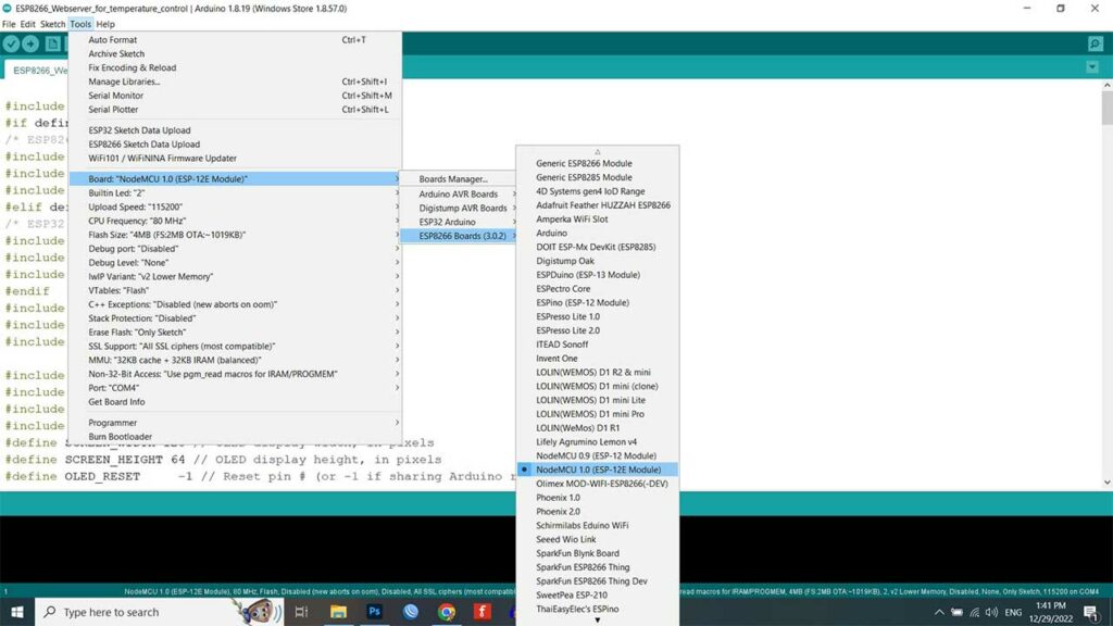
Go to Tools > Board > ESP8266 Boards > NodeMCU 1.0 (ESP8266-12E Module). Again go to Tools > Port Then choose the correct COM Port.
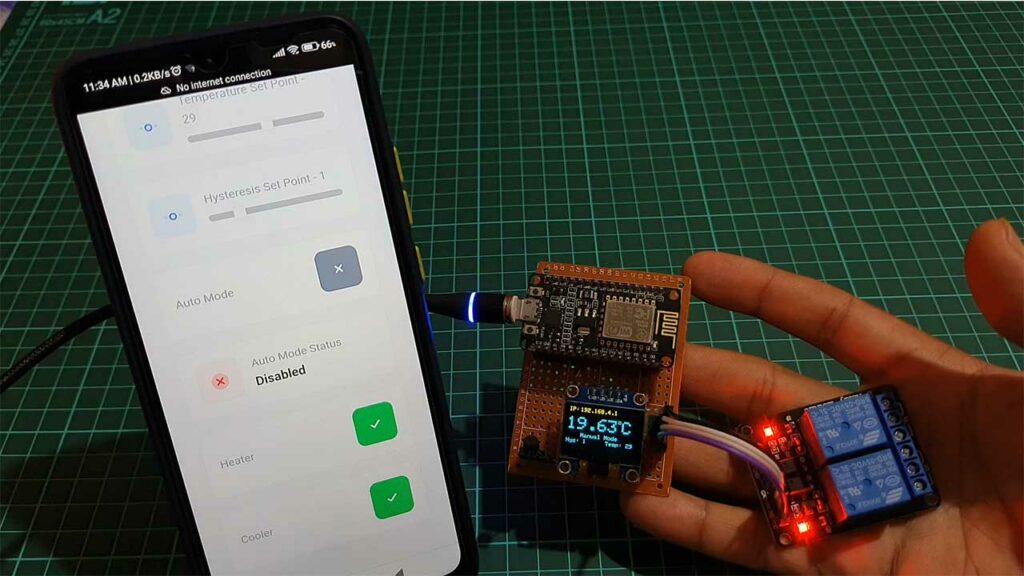
Finally, hit that upload button. It takes a few seconds to compile and upload the code. And that’s it! You now have a working temperature control system that you can access and control remotely through a web interface.
Conclusion
Thank you for reading this tutorial on how to build a temperature control system using an ESP8266 microcontroller, DS18B20 temperature sensor, and an OLED display. I hope that you found this tutorial helpful and that you were able to successfully build your own temperature control system. If you have any questions or comments, please leave them in the comments section below. Happy building!


I did not see any comments from this thread, maybe it’s too many hardware or function not mush tasyty for everyone.I am tackle on this project by DHT22 sensor, and a 0.91″ oled , and a single relay to substitute the One wire Temperature sensor (DS18B20 Sensor) ,a double channel relay. All other components are same. It is doable? and which part of code I need to modificate? Thanks!
Bonjour, Tous d’abord merci pour ce tuto très clair et très précis qui fonctionne sans problème.
Je souhaiterais apporter quelques petites modifications a votre projet.
Serait il possible que l’on échange par mail pour vous expliquer ma demande avec un ”café ”
Merci de votre retour
Hola, he intentado ejecutar este sketch en un esp8266, pero siempre me da el mimo error:
Compilation error: invalid user-defined conversion from ‘AsyncWebServer*’ to ‘AsyncWebServer&’ [-fpermissive]
En ESP32 igual.
Algo se me escapa y no lo veo. ¿Me podrías orientar?
Gracias.
It look like this project no longer works, it will not compile. i suspect that the ESPDash library is changed and gone paid for, the basic library no longer supports these commands.
I have changed the version of ESP-Dash to 3.00 and it now builds