IoT Smart Notice Board with MAX7219 ESP8266 & Blynk
MAX7219 Dot Matrix LED Display Controller with Blynk IoT using ESP8266

In today’s tutorial, we are building an IoT Smart Notice Board with MAX7219 Dot Matrix LED Display, ESP8266 & Blynk IoT Platform. In this project, we will create a versatile notice board that can display scrolling messages, control scroll speed, direction, and brightness, and even receive messages wirelessly from the Blynk IoT app.
Overview: IoT Smart Notice Board with Dot Matrix LED Display
Today, we present an exciting upgrade to a previously built notice board. We initially created a notice board using an ESP web server. But its control was limited to the local Wi-Fi network. However, with our new IoT-based Smart Notice Board, powered by MAX7219, NodeMCU, and Blynk, you can now have complete control from anywhere in the world.
It also opens up a world of possibilities for personal and professional applications. Whether you need to broadcast essential announcements in an office, display real-time information in a public space, or you’re on a business trip, vacation, or simply away from the physical location, your notice board can keep everyone informed and connected.
Imagine the convenience of remotely updating messages, adjusting scroll speed, and even modifying display settings, regardless of your location. With IoT technology, we’ve transformed a simple notice board into a globally accessible, interactive platform.
Components Required
Before we proceed, let’s gather the components required for this project. You will need:
| S.N | COMPONENTS NAME | QUANTITY | PURCHASE LINKS |
|---|---|---|---|
| 1 | NodeMCU ESP8266 Board | 1 | Amazon | AliExpress |
| 2 | MAX7219 Dot Matrix LED Display | 1 | Amazon | AliExpress |
| 3 | Breadboard | 1 | Amazon | AliExpress |
| 4 | 5V 2A Power Supply | 1 | Amazon | AliExpress |
| 5 | Jumper Cables | 5 | Amazon | AliExpress |
Circuit Connection
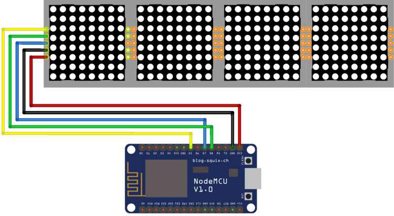
Now, let’s establish the circuit connection between the ESP8266 NodeMCU and the MAX7219 LED Module. Connect the CLK pin of the module to D5 on the NodeMCU, the DATA pin to D7, and the CS pin to D8. Provide Power to VCC and GND. If you are using multiple cascaded modules, make sure to follow the appropriate wiring.
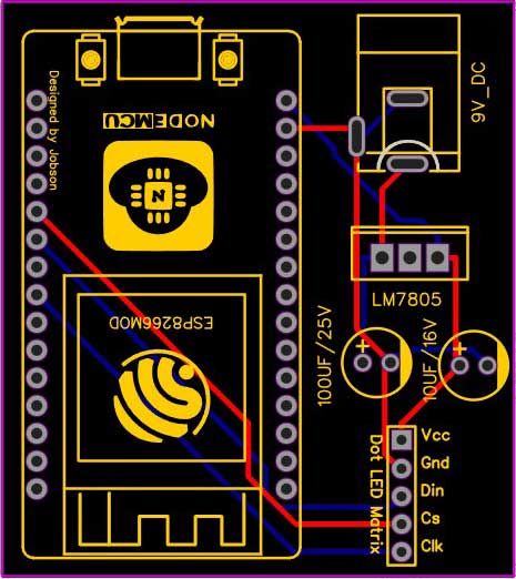
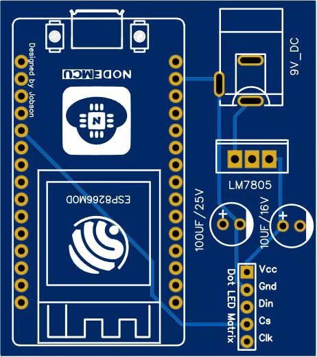
Project PCB Gerber File & PCB Ordering Online
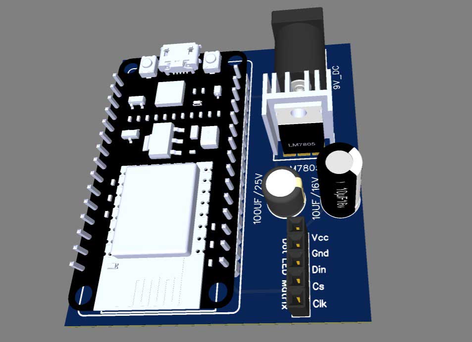
For a more professional and compact setup, you can consider designing a custom PCB for this project. You can use online PCB fabrication services like PCBWay.com to create a custom PCB based on your circuit design. This will provide a neat and reliable solution for your smart noticeboard.
The Gerber File for the PCB is given below. You can simply download the Gerber File and order the PCB from PCBWay.com.
Now you can visit the PCBWay official website by clicking here: PCBWay.com. So you will be directed to the PCBWay website.
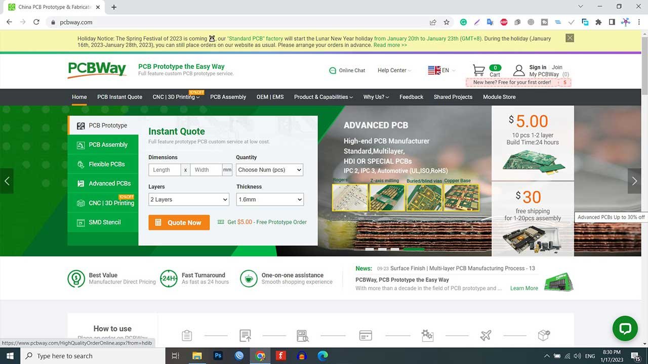
You can now upload the Gerber File to the Website and place an order. The PCB quality is superb & high standard. That is why most people trust PCBWay for PCB & PCBA Services. PCBWay is a leading manufacturer of high-quality PCBs and offers a wide range of services, including PCB fabrication, assembly, and components sourcing.
Setup Blynk IoT Web Dashboard
To control and monitor our smart notice board, we will set up a Blynk IoT web dashboard. Here’s how you can do it.
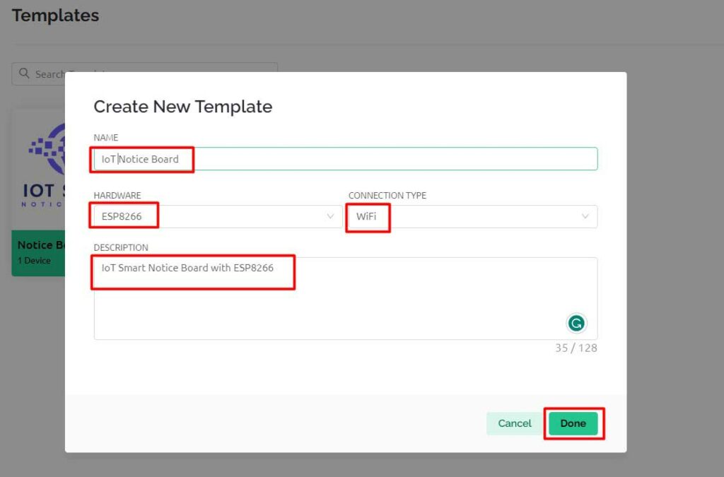
Create a Template
First, create a template in the Blynk IoT web dashboard. This template will serve as the interface for interacting with the notice board. You can customize the layout, add widgets, and define their functionality according to your requirements.
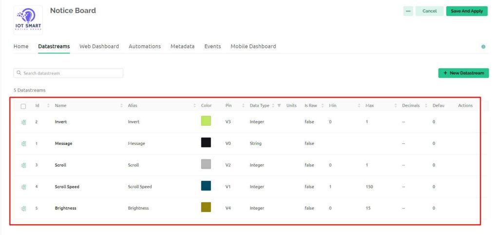
Configure Web Dashboard
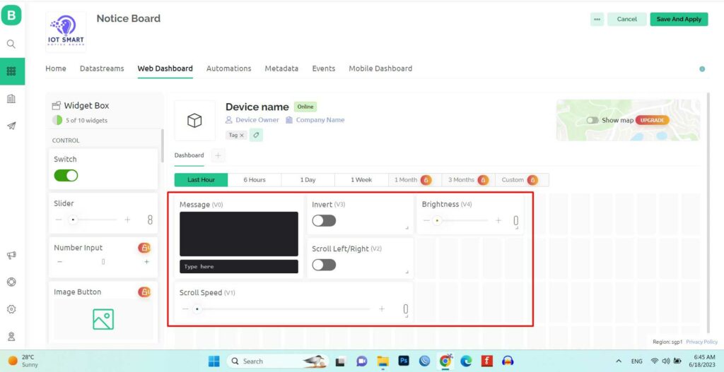
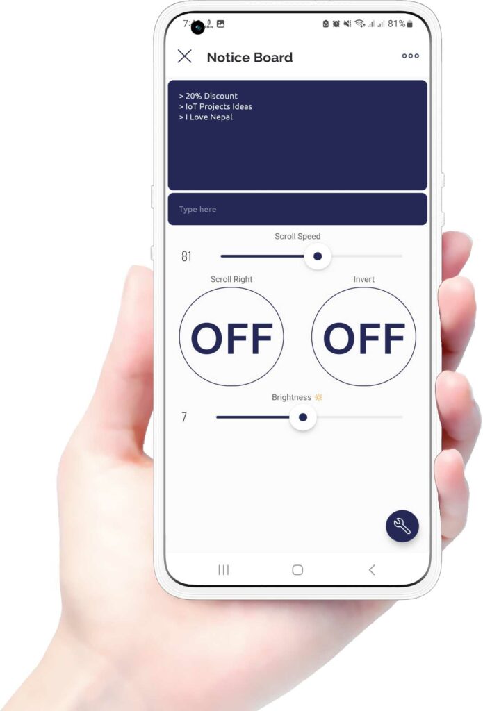
Next, configure the web dashboard by adding Terminal, Buttons, and Sliders widgets. Assign the virtual pins V0 to V4 to their datastreams. As shown in the images below. These widgets will allow you to send messages, and control scroll speed, direction, brightness, and other functionalities of the notice board.
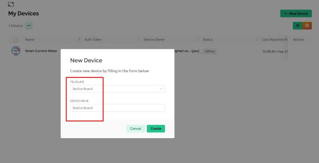
Add Device from Template
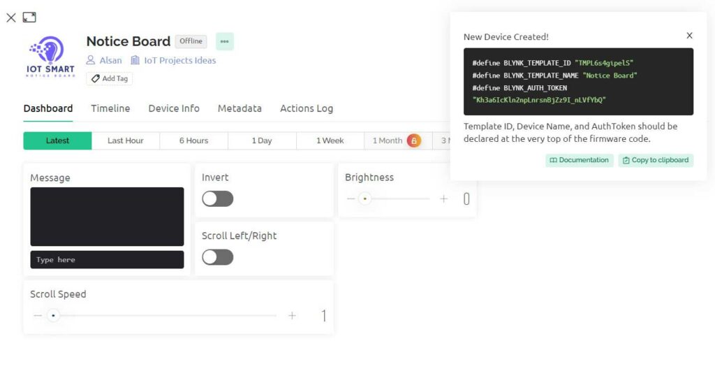
Once the template and web dashboard are set up, add the device from the template to associate your smart notice board with the Blynk IoT platform. This will establish the communication between the NodeMCU and the Blynk app.
Copy this code we will need it in the program code.
Program Source Code
Now, let’s take a look at the program source code for the ESP8266 NodeMCU. This code will enable communication between the NodeMCU, the MAX7219 LED Module, and the Blynk IoT platform.
#include <ESP8266WiFi.h>
#include <BlynkSimpleEsp8266.h>
#include <MD_Parola.h>     // include MajicDesigns Parola library
#include <MD_MAX72xx.h>    // include MajicDesigns MAX72xx LED matrix library
#include <SPI.h>

// Your WiFi credentials
char ssid[] = "xxxx-xxxx-xxxx-xxxx";
char pass[] = "xxxxx-xxxx-xxxx-xxxx";
char auth[] = "_xxxxxxxxxx-xxxxxxx-xxxxxx";

// Hardware setup
#define HARDWARE_TYPE MD_MAX72XX::FC16_HW
#define MAX_DEVICES 8 // If you're only using a single 32x8 display, set this to 4.

#define CLK_PIN   D5 // green
#define DATA_PIN  D7 // orange
#define CS_PIN    D8 // yellow
// define number of total cascaded modules

// Scrolling parameters
uint8_t frameDelay = 25;  // default frame delay value
textPosition_t scrollEffect = PA_LEFT; // default scroll effect is left
uint8_t scrollSpeed = 75; // default scroll speed value (change as needed)
bool scrollDirectionLeft = false; // flag to determine the scroll direction
bool invertDisplay = false; // flag to determine if the display is inverted
uint8_t brightnessLevel = 0; // default brightness level (range: 1-15)

// Global message buffers shared by Blynk and Scrolling functions
#define BUF_SIZE  512
char curMessage[BUF_SIZE];
char newMessage[BUF_SIZE];
bool newMessageAvailable = false;

// Define the LED matrix object
MD_Parola P = MD_Parola(HARDWARE_TYPE, CS_PIN, MAX_DEVICES);

void setup() {
  // Initialize serial communication
  Serial.begin(115200);

  // Connect to Wi-Fi
  WiFi.begin(ssid, pass);
  while (WiFi.status() != WL_CONNECTED) {
    delay(500);
    Serial.print(".");
  }
  Serial.println("Wi-Fi connected");

  // Initialize Blynk
  Blynk.begin(auth, ssid, pass);

  // Set up the scrolling display
  P.begin();
  P.displayClear();
  P.displaySuspend(false);
  P.displayScroll(curMessage, scrollEffect, scrollDirectionLeft ? PA_SCROLL_RIGHT : PA_SCROLL_LEFT, frameDelay);

  // Register a virtual pin handler for receiving messages from Blynk
  Blynk.virtualWrite(V0, "Test Message from ESP8266!");

  // Set up the initial message as the IP address
  sprintf(curMessage, "WiFi-Connected!");
  Serial.println(curMessage);
}

void loop() {
  // Run Blynk
  Blynk.run();

  // Check if a new message is available and update the display
  if (newMessageAvailable) {
    strcpy(curMessage, newMessage);
    newMessageAvailable = false;
    P.displayReset();
  }

  // Animate the display
  if (P.displayAnimate()) {
    if (newMessageAvailable) {
      strcpy(curMessage, newMessage);
      newMessageAvailable = false;
    }
    P.displayReset();
  }
}

// Blynk virtual pin handler for receiving messages
BLYNK_WRITE(V0) {
  strncpy(newMessage, param.asString(), BUF_SIZE);
  newMessageAvailable = true;
}

// Blynk virtual pin handler for receiving scroll speed
BLYNK_WRITE(V1) {
  scrollSpeed = param.asInt();
  frameDelay = map(scrollSpeed, 0, 150, 150, 0);
  P.setSpeed(frameDelay); // Update the scroll speed
}

// Blynk virtual pin handler for receiving scroll direction
BLYNK_WRITE(V2) {
  scrollDirectionLeft = param.asInt();
  P.displayClear();
  P.displayScroll(curMessage, scrollEffect, scrollDirectionLeft ? PA_SCROLL_RIGHT : PA_SCROLL_LEFT, frameDelay);
}

// Blynk virtual pin handler for receiving invert display
BLYNK_WRITE(V3) {
  invertDisplay = param.asInt();
  P.displayClear();
  P.setInvert(invertDisplay);
}

// Blynk virtual pin handler for receiving brightness level
BLYNK_WRITE(V4) {
  brightnessLevel = param.asInt();
  P.setIntensity(brightnessLevel); // Set the brightness level
}
Program Source Code Structure
The program begins with the inclusion of required libraries, such as ESP8266WiFi, Blynk Library, MD Parola, and MD MAX72xx. These libraries provide the necessary functions and utilities for Wi-Fi connectivity, Blynk integration, and controlling the LED matrix.
#include <ESP8266WiFi.h>
#include <BlynkSimpleEsp8266.h>
#include <MD_Parola.h>     // include MajicDesigns Parola library
#include <MD_MAX72xx.h>    // include MajicDesigns MAX72xx LED matrix library
#include <SPI.h>
Wi-Fi and Blynk Credentials
You will need to modify the code by replacing the default Wi-Fi credentials and Blynk authentication with your own. This ensures that the NodeMCU can connect to your Wi-Fi network and communicate with the Blynk IoT platform.
// Your WiFi credentials
char ssid[] = "xxxx-xxxx-xxxx-xxxx";
char pass[] = "xxxxx-xxxx-xxxx-xxxx";
char auth[] = "_xxxxxxxxxx-xxxxxxx-xxxxxx";
Hardware Setup
Next, the hardware setup is defined, specifying the type of LED matrix module, the number of cascaded devices, and the pin assignments for CLK, DATA, and CS. Make sure to match these pins with your circuit connection.
// Hardware setup
#define HARDWARE_TYPE MD_MAX72XX::FC16_HW
#define MAX_DEVICES 8 // If you're only using a single 32x8 display, set this to 4.

#define CLK_PIN   D5 // green
#define DATA_PIN  D7 // orange
#define CS_PIN    D8 // yellow
// define number of total cascaded modules
Scrolling parameters
The code also includes scrolling parameters, such as frame delay, scroll effect, scroll speed, scroll direction, display inversion, and brightness level. These parameters can be adjusted to customize the scrolling behavior and appearance of the notice board.
// Scrolling parameters
uint8_t frameDelay = 25;  // default frame delay value
textPosition_t scrollEffect = PA_LEFT; // default scroll effect is left
uint8_t scrollSpeed = 75; // default scroll speed value (change as needed)
bool scrollDirectionLeft = false; // flag to determine the scroll direction
bool invertDisplay = false; // flag to determine if the display is inverted
uint8_t brightnessLevel = 0; // default brightness level (range: 1-15)

// Global message buffers shared by Blynk and Scrolling functions
#define BUF_SIZE  512
char curMessage[BUF_SIZE];
char newMessage[BUF_SIZE];
bool newMessageAvailable = false;
Setup function
In the setup function, the program initializes the serial communication, connects to the Wi-Fi network, and starts the Blynk integration. It also initializes the LED matrix display, sets the initial message as ‘WiFi-Connected!’ When WiFi gets connected, and registers a virtual pin handler for receiving messages from the Blynk app.
void setup() {
  // Initialize serial communication
  Serial.begin(115200);

  // Connect to Wi-Fi
  WiFi.begin(ssid, pass);
  while (WiFi.status() != WL_CONNECTED) {
    delay(500);
    Serial.print(".");
  }
  Serial.println("Wi-Fi connected");

  // Initialize Blynk
  Blynk.begin(auth, ssid, pass);

  // Set up the scrolling display
  P.begin();
  P.displayClear();
  P.displaySuspend(false);
  P.displayScroll(curMessage, scrollEffect, scrollDirectionLeft ? PA_SCROLL_RIGHT : PA_SCROLL_LEFT, frameDelay);

  // Register a virtual pin handler for receiving messages from Blynk
  Blynk.virtualWrite(V0, "Test Message from ESP8266!");

  // Set up the initial message as the IP address
  sprintf(curMessage, "WiFi-Connected!");
  Serial.println(curMessage);
}
Loop function
The loop function is responsible for running the Blynk service, checking for new messages, and animating the display. It continuously checks for updates from the Blynk app, updates the display with new messages if available, and animates the scrolling display.
void loop() {
  // Run Blynk
  Blynk.run();

  // Check if a new message is available and update the display
  if (newMessageAvailable) {
    strcpy(curMessage, newMessage);
    newMessageAvailable = false;
    P.displayReset();
  }

  // Animate the display
  if (P.displayAnimate()) {
    if (newMessageAvailable) {
      strcpy(curMessage, newMessage);
      newMessageAvailable = false;
    }
    P.displayReset();
  }
}
Blynk virtual pin handlers
The code includes Blynk virtual pin handlers that respond to changes in the Blynk app. These handlers update the scroll speed, scroll direction, display inversion, and brightness level based on the values received from the Blynk app.
// Blynk virtual pin handler for receiving messages
BLYNK_WRITE(V0) {
  strncpy(newMessage, param.asString(), BUF_SIZE);
  newMessageAvailable = true;
}

// Blynk virtual pin handler for receiving scroll speed
BLYNK_WRITE(V1) {
  scrollSpeed = param.asInt();
  frameDelay = map(scrollSpeed, 0, 150, 150, 0);
  P.setSpeed(frameDelay); // Update the scroll speed
}

// Blynk virtual pin handler for receiving scroll direction
BLYNK_WRITE(V2) {
  scrollDirectionLeft = param.asInt();
  P.displayClear();
  P.displayScroll(curMessage, scrollEffect, scrollDirectionLeft ? PA_SCROLL_RIGHT : PA_SCROLL_LEFT, frameDelay);
}

// Blynk virtual pin handler for receiving invert display
BLYNK_WRITE(V3) {
  invertDisplay = param.asInt();
  P.displayClear();
  P.setInvert(invertDisplay);
}

// Blynk virtual pin handler for receiving brightness level
BLYNK_WRITE(V4) {
  brightnessLevel = param.asInt();
  P.setIntensity(brightnessLevel); // Set the brightness level
}
Now select your ESP8266 NodeMCU Board and COM port from the tools menu. Then Click the upload button to compile and upload code to the board.
Blynk IoT Mobile App Setup
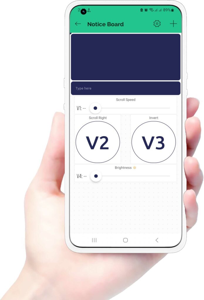
To control and monitor the smart notice board, you can also set up the Blynk mobile app on your smartphone. Here’s how you can do it.
Download and install the Blynk app from your app store. Create a new Blynk account or log in if you already have one. Then, click on the newly created project, Then add widgets, and assign them to the corresponding virtual pins.
Testing & Demo of the Project
Now that everything is set up, let’s test and demonstrate the functionality of our IoT-based Smart Notice Board.
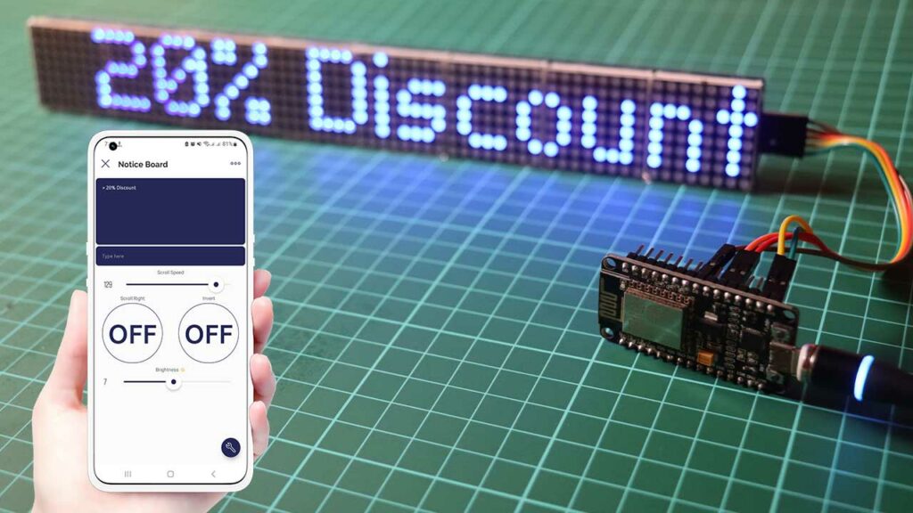
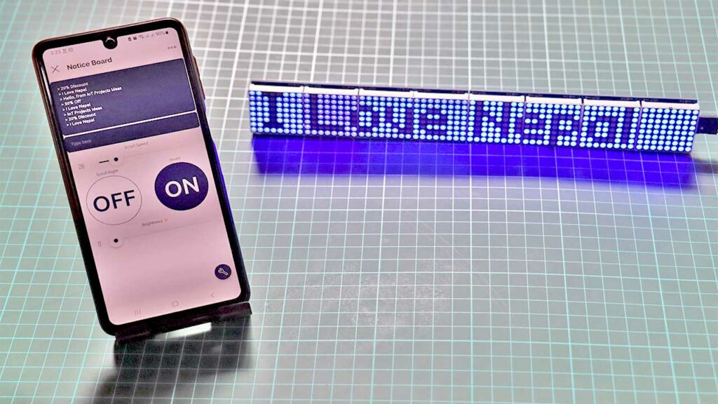
As you can see, the notice board displays scrolling messages that can be controlled remotely using the Blynk app.
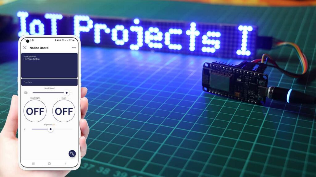
You can send new messages, adjust the scroll speed, change the direction, control brightness, and even invert the display.
Conclusion
In conclusion, we have successfully built an IoT Smart Notice Board with MAX7219 ESP8266 & Blynk IoT Platform. This project demonstrates the power of IoT in creating interactive and remotely controlled devices.
We hope you found this tutorial helpful and inspiring. Feel free to explore further and enhance the functionality of your smart notice board. Thank you for visiting, and happy tinkering!


hello i am writing again on here i will need also to work on this smart notice board. i am working on a project that will be needed to add this type of hardware to it. project is based on codeigniter. please contact me and lets have a conversation on how to archieve this projects. i live in finland.
hocam merhabalar projenizi 16×64 geniş ekranda görmek için nasıl bir yol izlemeliyim
şimdiden teşekkür ederim iyi günler
Hi,
need help to install the library in the Arduino_IDE 2.2.1 always comes error message is no library ?