Read Internal Temperature Sensor Value from Raspberry Pi Pico
Read OnBoard Temperature Sensor Value from Raspberry Pi Pico
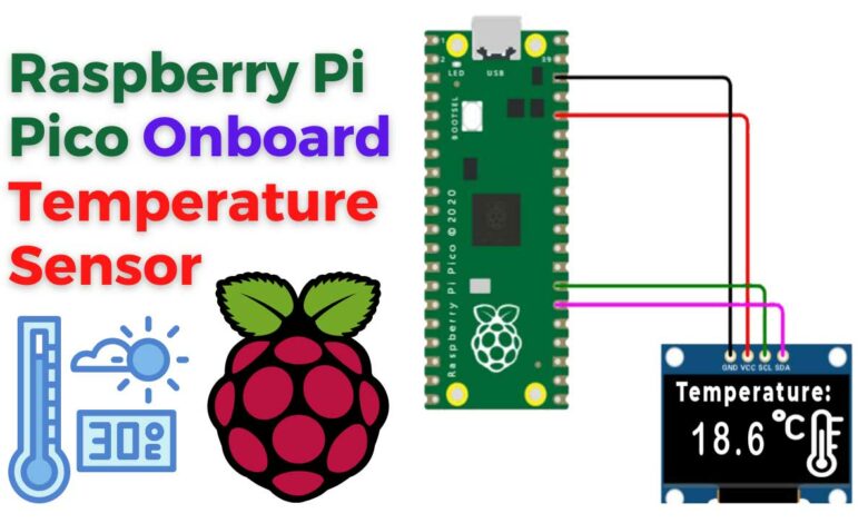
Read Raspberry Pi Pico OnBoard temperature sensor
In this tutorial, we will Read Internal Temperature Sensor Value from Raspberry Pi Pico and display it on an OLED screen. The Raspberry Pi Pico has an internal temperature sensor that is connected to one of its ADC pins. We will connect an I2C OLED display to the Raspberry Pi Pico and use it to display the temperature data. The circuit will be assembled using a breadboard and jumper wires.
Components Required
To complete this tutorial, you will need the following components:
| S.N | COMPONENTS NAME | QUANTITY | PURCHASE LINKS |
|---|---|---|---|
| 1 | Raspberry Pi Pico Basic Starter Kit | 1 | Amazon | AliExpress |
| 2 | Raspberry Pi Pico | 1 | Amazon | AliExpress |
| 3 | 0.96" I2C OLED Display | 1 | Amazon | AliExpress |
| 5 | Breadboard | 1 | Amazon | AliExpress |
| 6 | Jumper Wires | 10 | Amazon | AliExpress |
Interfacing SSD1306 OLED Display with Raspberry Pi Pico
To display the temperature value on the OLED display. We need to establish a connection between the Raspberry Pi Pico and the OLED display. The connection diagram is as follows:
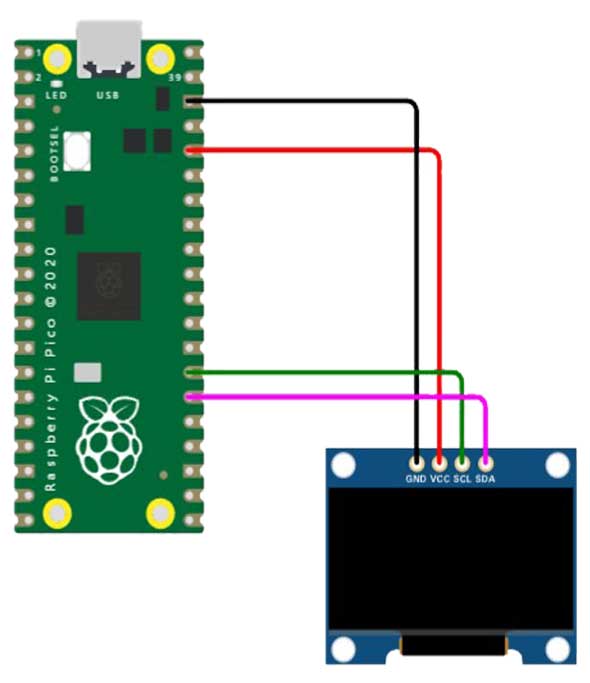
Connect the SDA and SCL (I2C Pins) pins of the OLED display to the Raspberry Pi Pico GP20 and GP21 pins, respectively. You can use the breadboard to assemble the circuit as shown here.

Temperature Sensor of Raspberry Pi Pico
The internal temperature sensor that comes with the Raspberry Pi Pico is connected to one of the ADCs. ADC refers to Analog-to-Digital Converters. The ADC pin supports a range of values, which is determined by the input voltage applied to the pin.
In the RP2040 Pico Board, the ADC pins support 12 bits. Which means that the value can go from 0 to 4095. But the MicroPython code can scale the ADC values to a 16-bit range. So we effectively get the range from 0 to 65535. The microcontroller works at 3.3 V. That means that an ADC pin will return a value of 65535 when 3.3 V is applied to it or 0 when there is no voltage. We can obtain all the in-between values when the voltage applied to the pin is between 0 and 3.3 V.
You can check the Raspberry Pi Getting Started Tutorial to learn more about its specifications, pins & details.
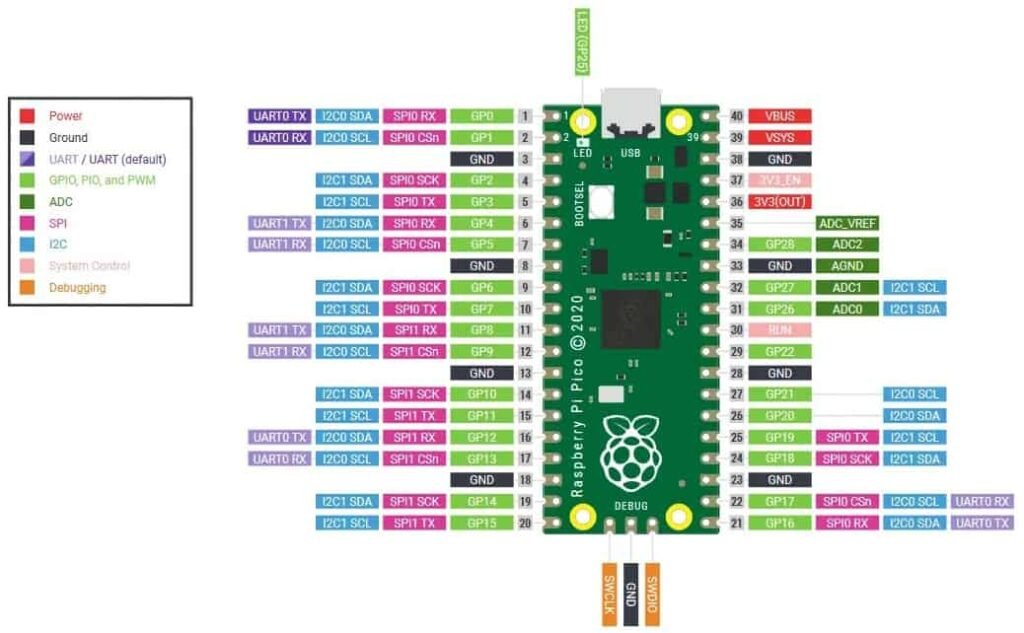
The Raspberry Pi Pico board has a set of ADC pins. Basically, it has its own numbering scheme instead of the traditional GPIO pin numbers. The pins labeled ADC0, ADC1, ADC2, and ADC_VREF (technically ADC3). These are the four externally accessible ADC pins. So, the temperature sensor can be accessed as ADC4.
Reading the Pi Pico Temperature Value with MicroPython Code
To read the temperature value, we can use MicroPython code. The code imports the machine and utime modules, and creates an object for the temperature sensor using the ADC() class. It then sets a conversion factor and enters a loop to read the temperature value. Then it converts readings to the Celsius scale. The converted temperature value is then printed to the Shell window.
import machine
import utime

sensor_temp = machine.ADC(4)
conversion_factor = 3.3 / (65535)

while True:
    reading = sensor_temp.read_u16() * conversion_factor
    temperature = 27 - (reading - 0.706)/0.001721
    print(temperature)
    utime.sleep(2)
Code Explanation:
We first import the machine and utime modules. The machine module provides the ADC() class to work with ADC pins.
import machine
import utime
The sensor_temp variable is created as an object of the ADC class with pin 4 as its argument.
sensor_temp = machine.ADC(4)
We set a conversion factor to convert the 16-bit temperature value back to volts. That is done based on the 3.3 V maximum voltage used by the Pico board.
conversion_factor = 3.3 / (65535)
In the while loop, we read the temperature value using the sensor_temp object’s read_u16() method. Then multiply it with the conversion factor.
reading = sensor_temp.read_u16() * conversion_factor
The temperature value is then converted to the Celsius scale using the following equation. It calculates the temperature based on the voltage delivered by the sensor.
temperature = 27 - (reading - 0.706)/0.001721
If you want to convert the temperature value from degrees Celcius to Fahrenheit. Then you can use this mathematical equation.
fahrenheit_degrees = celsius_degrees * 9 / 5 + 32
Finally, the temperature value is printed on the Shell window. At last delay of 2 seconds is created.
print(temperature)
utime.sleep(2)
Displaying the Raspberry Pi Pico Temperature Values on OLED
To display the temperature value on an OLED screen. We need to write an OLED driver code as the SSD1306 driver is not available. The code is divided into two parts: ssd1306.py and main.py. The ssd1306.py file contains the OLED driver code. Meanwhile, the main.py file contains the code to display the temperature value on the OLED screen.
ssd1306.py
To display the temperature value on an OLED screen. we need to write an SSD1306 OLED driver code as the SSD1306 driver is not available by default. Open a new tab in your Thonny IDE and copy the following code. Save the file as ssd1306.py in Raspberry Pi Pico.
# MicroPython SSD1306 OLED driver, I2C and SPI interfaces

from micropython import const
import framebuf


# register definitions
SET_CONTRAST = const(0x81)
SET_ENTIRE_ON = const(0xA4)
SET_NORM_INV = const(0xA6)
SET_DISP = const(0xAE)
SET_MEM_ADDR = const(0x20)
SET_COL_ADDR = const(0x21)
SET_PAGE_ADDR = const(0x22)
SET_DISP_START_LINE = const(0x40)
SET_SEG_REMAP = const(0xA0)
SET_MUX_RATIO = const(0xA8)
SET_COM_OUT_DIR = const(0xC0)
SET_DISP_OFFSET = const(0xD3)
SET_COM_PIN_CFG = const(0xDA)
SET_DISP_CLK_DIV = const(0xD5)
SET_PRECHARGE = const(0xD9)
SET_VCOM_DESEL = const(0xDB)
SET_CHARGE_PUMP = const(0x8D)

# Subclassing FrameBuffer provides support for graphics primitives
# http://docs.micropython.org/en/latest/pyboard/library/framebuf.html
class SSD1306(framebuf.FrameBuffer):
    def __init__(self, width, height, external_vcc):
        self.width = width
        self.height = height
        self.external_vcc = external_vcc
        self.pages = self.height // 8
        self.buffer = bytearray(self.pages * self.width)
        super().__init__(self.buffer, self.width, self.height, framebuf.MONO_VLSB)
        self.init_display()

    def init_display(self):
        for cmd in (
            SET_DISP | 0x00,  # off
            # address setting
            SET_MEM_ADDR,
            0x00,  # horizontal
            # resolution and layout
            SET_DISP_START_LINE | 0x00,
            SET_SEG_REMAP | 0x01,  # column addr 127 mapped to SEG0
            SET_MUX_RATIO,
            self.height - 1,
            SET_COM_OUT_DIR | 0x08,  # scan from COM[N] to COM0
            SET_DISP_OFFSET,
            0x00,
            SET_COM_PIN_CFG,
            0x02 if self.width > 2 * self.height else 0x12,
            # timing and driving scheme
            SET_DISP_CLK_DIV,
            0x80,
            SET_PRECHARGE,
            0x22 if self.external_vcc else 0xF1,
            SET_VCOM_DESEL,
            0x30,  # 0.83*Vcc
            # display
            SET_CONTRAST,
            0xFF,  # maximum
            SET_ENTIRE_ON,  # output follows RAM contents
            SET_NORM_INV,  # not inverted
            # charge pump
            SET_CHARGE_PUMP,
            0x10 if self.external_vcc else 0x14,
            SET_DISP | 0x01,
        ):  # on
            self.write_cmd(cmd)
        self.fill(0)
        self.show()

    def poweroff(self):
        self.write_cmd(SET_DISP | 0x00)

    def poweron(self):
        self.write_cmd(SET_DISP | 0x01)

    def contrast(self, contrast):
        self.write_cmd(SET_CONTRAST)
        self.write_cmd(contrast)

    def invert(self, invert):
        self.write_cmd(SET_NORM_INV | (invert & 1))

    def show(self):
        x0 = 0
        x1 = self.width - 1
        if self.width == 64:
            # displays with width of 64 pixels are shifted by 32
            x0 += 32
            x1 += 32
        self.write_cmd(SET_COL_ADDR)
        self.write_cmd(x0)
        self.write_cmd(x1)
        self.write_cmd(SET_PAGE_ADDR)
        self.write_cmd(0)
        self.write_cmd(self.pages - 1)
        self.write_data(self.buffer)


class SSD1306_I2C(SSD1306):
    def __init__(self, width, height, i2c, addr=0x3C, external_vcc=False):
        self.i2c = i2c
        self.addr = addr
        self.temp = bytearray(2)
        self.write_list = [b"x40", None]  # Co=0, D/C#=1
        super().__init__(width, height, external_vcc)

    def write_cmd(self, cmd):
        self.temp[0] = 0x80  # Co=1, D/C#=0
        self.temp[1] = cmd
        self.i2c.writeto(self.addr, self.temp)

    def write_data(self, buf):
        self.write_list[1] = buf
        self.i2c.writevto(self.addr, self.write_list)


class SSD1306_SPI(SSD1306):
    def __init__(self, width, height, spi, dc, res, cs, external_vcc=False):
        self.rate = 10 * 1024 * 1024
        dc.init(dc.OUT, value=0)
        res.init(res.OUT, value=0)
        cs.init(cs.OUT, value=1)
        self.spi = spi
        self.dc = dc
        self.res = res
        self.cs = cs
        import time

        self.res(1)
        time.sleep_ms(1)
        self.res(0)
        time.sleep_ms(10)
        self.res(1)
        super().__init__(width, height, external_vcc)

    def write_cmd(self, cmd):
        self.spi.init(baudrate=self.rate, polarity=0, phase=0)
        self.cs(1)
        self.dc(0)
        self.cs(0)
        self.spi.write(bytearray([cmd]))
        self.cs(1)

    def write_data(self, buf):
        self.spi.init(baudrate=self.rate, polarity=0, phase=0)
        self.cs(1)
        self.dc(1)
        self.cs(0)
        self.spi.write(buf)
        self.cs(1)
main.py
After saving the ssd1306.py on Raspberry Pi Pico. Create a new tab again and copy the following code. Save this code as main.py.
# Display Image & text on I2C driven ssd1306 OLED display
from machine import Pin, I2C
from ssd1306 import SSD1306_I2C
import machine
import utime
sensor_temp = machine.ADC(4)
conversion_factor = 3.3 / (65535)
WIDTH = 128 # oled display width
HEIGHT = 64 # oled display height
i2c = I2C(0, scl=Pin(9), sda=Pin(8), freq=200000) # Init I2C using pins GP8 & GP9 (default I2C0 pins)
print("I2C Address : "+hex(i2c.scan()[0]).upper()) # Display device address
print("I2C Configuration: "+str(i2c)) # Display I2C config
oled = SSD1306_I2C(WIDTH, HEIGHT, i2c) # Init oled display
while True:
reading = sensor_temp.read_u16() * conversion_factor
temperature = 27 - (reading - 0.706)/0.001721
print(temperature)
# Clear the oled display in case it has junk on it.
oled.fill(0)
# Add some text
oled.text("Temp: ",6,8)
oled.text(str(round(temperature,2)),50,8)
oled.text("*C",95,8)
utime.sleep(2)
# Finally update the oled display so the image & text is displayed
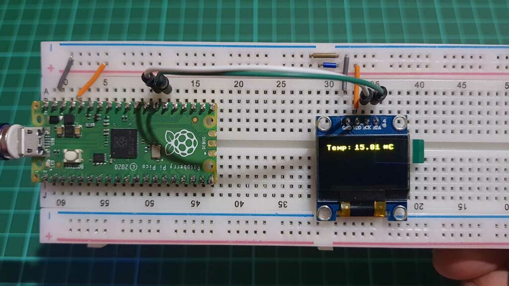
oled.show()Testing
Once you run the code, the OLED display will start displaying the temperature value on the OLED screen.
Conclusion
This is how you can Read the internal Temperature Sensor Value from Raspberry Pi Pico using MicroPython Programming. Additionally, you can also connect an external temperature sensor like DS18B20 with the RPI Pico to read external temperatures.