LoRa based Two Way Wireless Communication System with Arduino
Wireless Two Way Communication with LoRa & Arduino
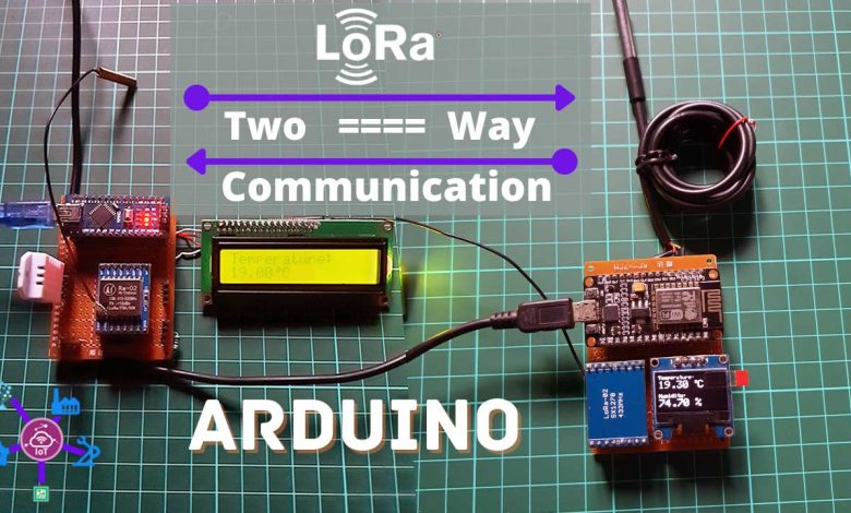
In this tutorial, you will learn how to make a LoRa based two way wireless communication system with Arduino. This is a complete two-way communication system based on the Arduino and the most powerful and popular 433MHz SX1278 LoRa Transceiver modules.
Overview: LoRa SX1278 based Two Way Communication
In my previous project, I had used SX1278 LoRa transceiver modules and I explained some basic things including the SX1278 Lora module Pinout, technical specifications, and its interfacing with the Arduino. I also interfaced the ESP8266 module to the receiver end and uploaded data to Blynk IoT Cloud. It was a LoRa based wireless one way sensor monitoring & automation system. So, if you are interested in such a project then I highly recommend you should first read my LoRa based IoT Smart Irrigation System with ESP8266 & Blynk 2.0
Recommended Tutorials:
In this tutorial, you will learn how to make a wireless two way communication system using Arduino and SX1278 LoRa Transceiver modules. Here I am using Arduino & ESP8266 Module but you can use any Arduino on both nodes.
The DHT22 Temperature and Humidity sensor and 16×2 I2C LCD Display are connected to the Arduino Node. While to the ESP8266 Node a DS18B20 Temperature Sensor and 0.96 inch I2C OLED Display are connected.
The parameters of the DHT22 sensor Temperature and Humidity are sent from the Arduino Node to the ESP8266 Node and are displayed on an OLED Display. The DS18B20 temperature sensor data from ESP8266 Node is sent to Arduino Node and is displayed on a 16×2 LCD Display.
Components Required
For LoRa based two way wireless communication system, we required the following components.
| S.N | Components Name | Quantity | |
|---|---|---|---|
| 1 | NodeMCU ESP8266-12E Board | 1 | https://amzn.to/3sCrEbj |
| 2 | DHT22 Temperature & Humidity Sensor | 1 | https://amzn.to/32VEw1X |
| 3 | DS18B20 waterproof Temperature Sensor | 1 | https://amzn.to/33EkMQq |
| 4 | 0.96" I2C OLED Display | 1 | https://amzn.to/3kvENyc |
| 5 | Arduino Nano | 1 | https://amzn.to/3Hf7zvN |
| 6 | Few jumpers wires | 20 | https://amzn.to/3klh0A4 |
| 7 | LoRa SX1278 Transceiver Module | 2 | https://amzn.to/3G6xapO |
*Please Note: These are affiliate links. I may make a commission if you buy the components through these links. I would appreciate your support in this way!
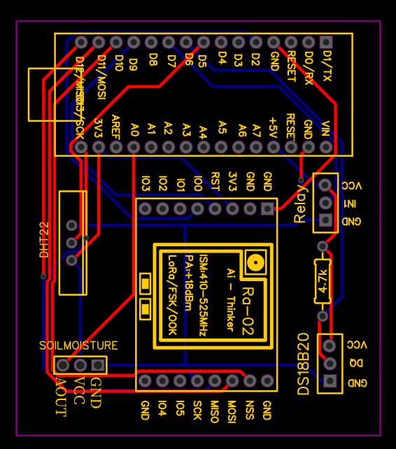
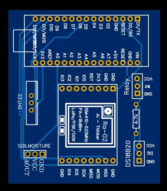
Arduino SX1278 LoRa Node Circuit:
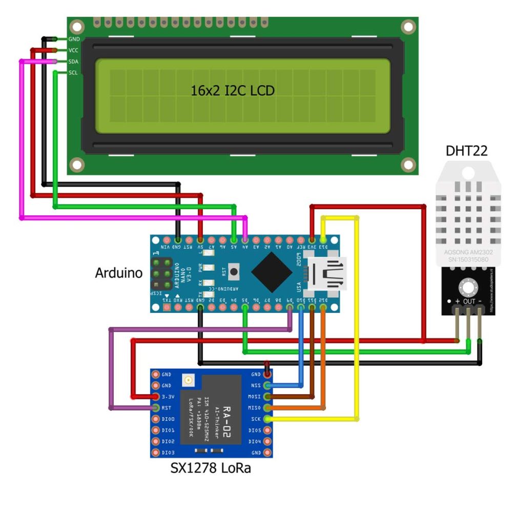
This is the circuit diagram of the Arduino Node, the connection of the SX1278 Lora module, DHT22, and 16×2 I2C LCD remains exactly as shown here. The VCC of the LoRa module is connected with the 3.3V of the Arduino. The MISO Pin of the LoRa module is connected with Arduino’s pin 12. The MOSI pin is connected with the Arduino’s pin 11. The SCK pin of the LoRa module is connected with Arduino’s pin 13. The NSS pin is connected with the Arduino’s pin 10 and the ground pin of the LoRa module is connected with the Arduino’s GND.
Out pin of the DHT22 sensor is connected to the D5 pin of the Arduino. Whereas VCC and GND are connected to 3.3V and GND pins of Arduino, respectively 16×2 LCD needs 5V supply so GND and VCC are connected to 5V pin and GND pin of Arduino. I2C pins SCL and SDA are also connected to Arduino’s I2C Pins A5 and A4 respectively.
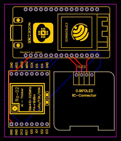
SX1278 LoRa based ESP8266 Node Circuit:
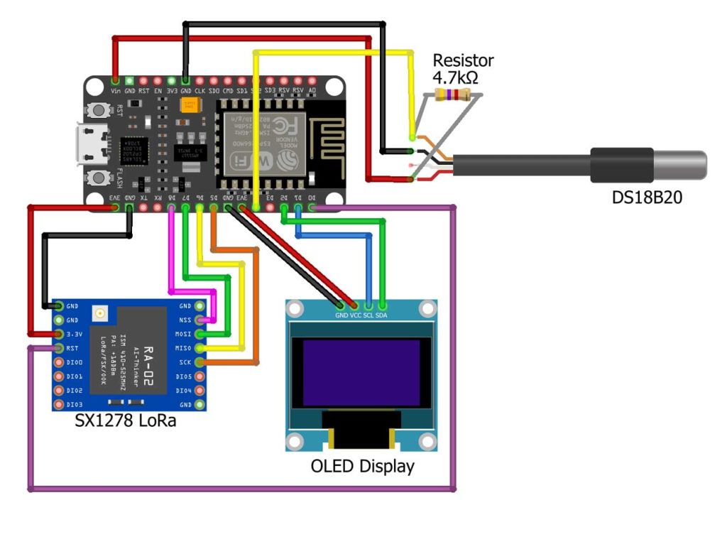
This is the circuit diagram of the ESP8266 Node. The VCC of the SX1278 Lora module is connected with the 3.3V of the NodeMCU. The MISO Pin of the LoRa module is connected with the NodeMCU pin D6. The MOSI pin is connected with the NodeMCU pin D7. The SCK pin of the LoRa module is connected with NodeMCU pin D5. The NSS pin is connected with pin D8 and the ground pin of the LoRa module is connected with the NodeMCU GND. The VCC and GND pins of the SSD1306 Oled display module are connected with the NodeMCU 3.3V and GND pins. The SDA and SCL pins of the Oled display module are connected with the NodeMCU I2C pins D1 and D2.
The DS18B20 temperature sensor requires a 5V supply so the VCC pin is connected to the Vin pin of NodeMCU. Data pin and GND are connected to D4 and GND pins respectively. A 4.7k ohm pullup resistor is used in between the VCC and Data Pin of the DS18B20 sensor.
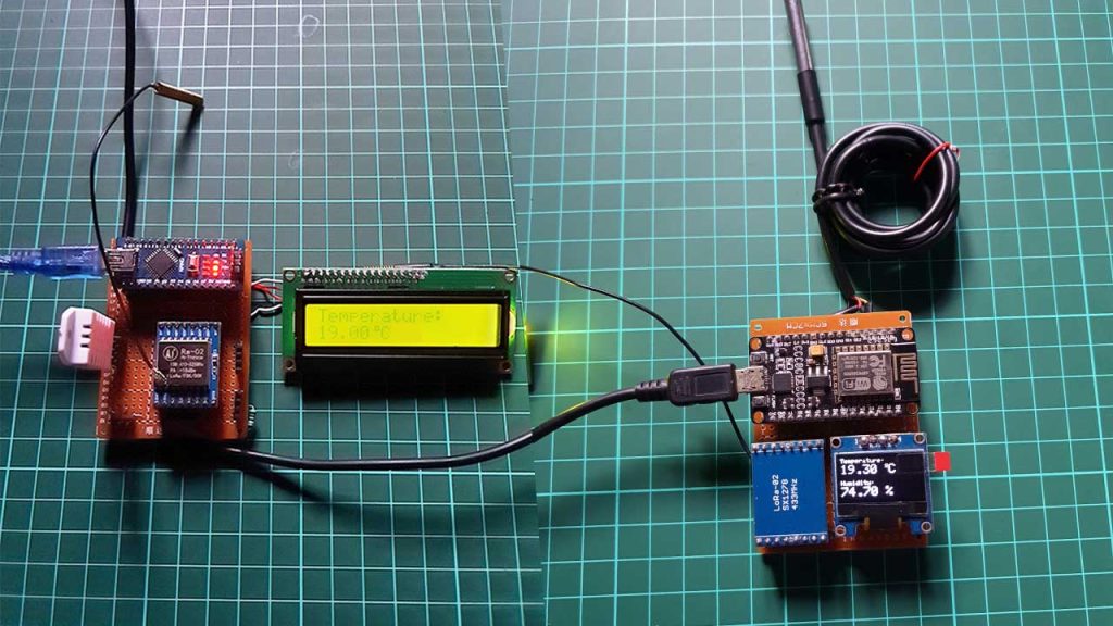
I connected everything as per the circuit diagrams. So, the node to which the DHT22 sensor and 16×2 LCD module are connected is the Arduino Node, and the Node to which the DS18B20 and Oled display module are connected is the ESP8266 Node.
Project PCB Gerber File & PCB Ordering Online
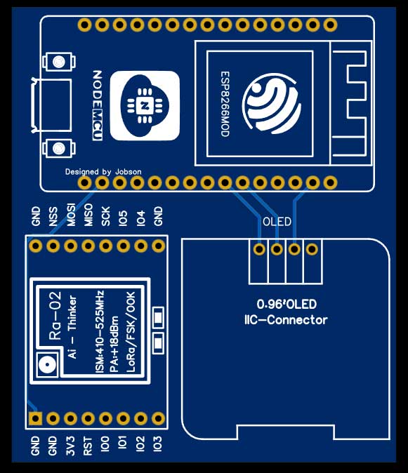
You can simply assemble the circuit on a breadboard. But To remove messy wiring and give a clean look, I designed a PCB prototype for this project. It is also helpful for troubleshooting without any errors. You can download the Gerber file of my PCB Design from the link attached below. The PCB looks like the image shown below.
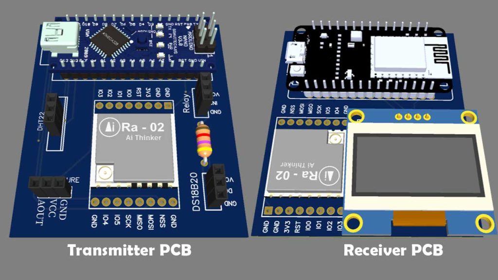
I provided the Gerber File for LoRa based Two Way Wireless Communication System with Arduino PCB below.
You can simply download the Gerber File and order your custom PCB from PCBWay

Visit the PCBWay official website by clicking here: https://www.PCBWay.com/. Simply upload your Gerber File to the Website and place an order. I prefer PCBWay for ordering custom PCBs. PCBWay is a place that brings manufacturers and customers together. They have more than a decade of experience in this field of fabrication, prototyping, and assembling PCBs. PCBWay have proved their focus to their customers’ needs in terms of cost-effectiveness, delivery, and quality. And this can be proved by their outstanding customer reviews.
Program Code
Before you start programming, first of all, make sure you download and install all the necessary library files.
- LoRa Library
- DHT.h Library
- DallasTemperature.h Library
- OneWire.h Library
- Liquid Crystal I2C LCD Library
- Adafruit_SSD1306.h Library
- Adafruit_Sensor.h Library
- Adafruit GFX.h Library
Arduino & SX1278 LoRa Node Code:
#include <Wire.h>
#include <SPI.h>
#include <LoRa.h>
#include <DHT.h>
#include <LiquidCrystal_I2C.h>

#define DHTPIN 5          //pin where the dht22 is connected
DHT dht(DHTPIN, DHT22);
#define ss 10
#define rst 9
#define dio0 2

LiquidCrystal_I2C lcd(0x27, 16, 2);
// Degree symbol:
byte Degree[] = {
  B00111,
  B00101,
  B00111,
  B00000,
  B00000,
  B00000,
  B00000,
  B00000
};

String outgoing;
byte msgCount = 0;            // count of outgoing messages
byte localAddress = 0xBB;     // address of this device
byte destination = 0xFF;      // destination to send to
long lastSendTime = 0;        // last send time
int interval = 50;          // interval between sends

String temp;     //DS18B20 temperature

void setup()
{
  Serial.begin(115200);
  dht.begin();
    // Start the LCD and turn on the backlight:
  lcd.begin();
  lcd.backlight();
  lcd.clear();
  // Create a custom character:
  lcd.createChar(0, Degree);

  while (!Serial);
  Serial.println("LoRa Two Way Communication");
  LoRa.setPins(ss, rst, dio0);
  if (!LoRa.begin(433E6)) {
    Serial.println("Starting LoRa failed!");
    delay(100);
    while (1);
  }
}

void loop()
{
  if (millis() - lastSendTime > interval) {
    //--------------- Start Sending DHT22 Data --------------------
    float temperature = dht.readTemperature();
    float humidity = dht.readHumidity();


    if (isnan(humidity) || isnan(temperature))
    {
      Serial.println("Failed to read from DHT sensor!");
      return;
    }

    Serial.print("Temperature: ");
    Serial.print(temperature);
    Serial.println("°C");

    Serial.print("Humidity: ");
    Serial.print(humidity);
    Serial.println("%");
    Serial.println("");

    String message = String(temperature) + "/" + String(humidity);
  sendMessage(message);
    // Serial.println("Sending " + message);
    lastSendTime = millis();            // timestamp the message
    interval = random(50) + 100;    // 2-3 seconds
  }

  // parse for a packet, and call onReceive with the result:
  onReceive(LoRa.parsePacket());
}

void sendMessage(String outgoing) {
  LoRa.beginPacket();                   // start packet
  LoRa.write(destination);              // add destination address
  LoRa.write(localAddress);             // add sender address
  LoRa.write(msgCount);                 // add message ID
  LoRa.write(outgoing.length());        // add payload length
  LoRa.print(outgoing);                 // add payload
  LoRa.endPacket();                     // finish packet and send it
  msgCount++;                           // increment message ID
}


//--------------- Start receiving DS18B20 Temperature Data --------------------
void onReceive(int packetSize) {
  if (packetSize == 0) return;

  // read packet header bytes:
  int recipient = LoRa.read();          // recipient address
  byte sender = LoRa.read();            // sender address
  byte incomingMsgId = LoRa.read();     // incoming msg ID
  byte incomingLength = LoRa.read();    // incoming msg length


  // received a packet
  Serial.print("Received packet:  ");
  String LoRaData = LoRa.readString();
  Serial.print(LoRaData);
  // read packet
  while (LoRa.available()) {
    Serial.print((char)LoRa.read());
  }
  // print RSSI of packet
  Serial.print("' with RSSI ");
  Serial.println(LoRa.packetRssi());


  temp = LoRaData.substring(0, LoRaData.length());

  Serial.print(F("DS18B20 Temperature: "));
  Serial.print(temp);
  Serial.println(F(" °C"));
  Serial.println();

    // Print the temperature on the LCD;
  lcd.setCursor(0,0);
  lcd.print("Temperature:");
  lcd.setCursor(0,1);
  lcd.print(temp);
  lcd.write(0); // print the custom character
  lcd.print("C");
  delay(1000);
}
ESP8266 & SX1278 LoRa Node Code:
#include <SPI.h>
#include <Wire.h>
#include <LoRa.h>
#include <Adafruit_Sensor.h>
#include <Adafruit_GFX.h>
#include <Adafruit_SSD1306.h>
#include <OneWire.h>
#include <DallasTemperature.h>

#define ONE_WIRE_BUS 2   //GPIO 2
OneWire oneWire(ONE_WIRE_BUS);
DallasTemperature sensors(&oneWire);

#define ss 15  //GPIO 15
#define rst 16  //GPIO 16
#define dio0 4  //GPIO 4

String outgoing;
byte msgCount = 0;            // count of outgoing messages
byte localAddress = 0xBB;     // address of this device
byte destination = 0xFF;      // destination to send to
long lastSendTime = 0;        // last send time
int interval = 50;          // interval between sends

#define SCREEN_WIDTH 128 // OLED display width, in pixels
#define SCREEN_HEIGHT 64 // OLED display height, in pixels
#define OLED_RESET -1 // Reset pin # (or -1 if sharing Arduino reset pin)
Adafruit_SSD1306 display(SCREEN_WIDTH, SCREEN_HEIGHT, &Wire, OLED_RESET);

String recivcounter;
String temperature;
String humidity;

void setup() {
  Serial.begin(115200);
  sensors.begin(); // Dallas temperature

  while (!Serial);

  Serial.println("Two Way Communication");

  LoRa.setPins(ss, rst, dio0);

  if (!LoRa.begin(433E6)) {
    Serial.println("Starting LoRa failed!");
    while (1);
  }
  display.begin(SSD1306_SWITCHCAPVCC, 0x3C); //initialize with the I2C addr 0x3C (128x64)
  display.clearDisplay();
  display.setTextColor(WHITE);
}


void loop() {
  if (millis() - lastSendTime > interval) {
    //--------------- Start Sending DS18B20 Temperature Data --------------------
    sensors.requestTemperatures();
    float temp = sensors.getTempCByIndex(0);
    Serial.print("DS18B20 Temperature: ");
    Serial.print(temp);
    Serial.println(" °C");
    Serial.println();

    String message = String(temp);
    sendMessage(message);

    //Serial.println("Sending " + message);
    lastSendTime = millis();            // timestamp the message
    interval = random(50) + 100;
  }

  // parse for a packet, and call onReceive with the result:
  onReceive(LoRa.parsePacket());
}

void sendMessage(String outgoing) {
  LoRa.beginPacket();                   // start packet
  LoRa.write(destination);              // add destination address
  LoRa.write(localAddress);             // add sender address
  LoRa.write(msgCount);                 // add message ID
  LoRa.write(outgoing.length());        // add payload length
  LoRa.print(outgoing);                 // add payload
  LoRa.endPacket();                     // finish packet and send it
  msgCount++;                           // increment message ID
}


void onReceive(int packetSize) {
  if (packetSize == 0) return;          // if there's no packet, return

  // read packet header bytes:
  int recipient = LoRa.read();          // recipient address
  byte sender = LoRa.read();            // sender address
  byte incomingMsgId = LoRa.read();     // incoming msg ID
  byte incomingLength = LoRa.read();    // incoming msg length

  //--------------- Start receiving DHT22 Data --------------------

  // try to parse packet
  int pos1, pos2;

  // received a packet
  Serial.print("Received packet:  ");
  String LoRaData = LoRa.readString();
  Serial.print(LoRaData);
  // read packet
  while (LoRa.available()) {
    Serial.print((char)LoRa.read());
  }
  // print RSSI of packet
  Serial.print("' with RSSI ");
  Serial.println(LoRa.packetRssi());

  pos1 = LoRaData.indexOf('/');

  temperature = LoRaData.substring(0, pos1);
  humidity = LoRaData.substring(pos1 + 1, LoRaData.length());


  Serial.print(F("Temperature: "));
  Serial.print(temperature);
  Serial.println(F("°C"));

  Serial.print(F("Humidity = "));
  Serial.print(humidity);
  Serial.println(F("%"));

  Serial.println();


  display.clearDisplay();

  // display temperature
  display.setTextSize(1);
  display.setCursor(0, 0);
  display.print("Temperature: ");
  display.setTextSize(2);
  display.setCursor(0, 10);
  display.print(temperature);
  display.print(" ");
  display.setTextSize(1);
  display.cp437(true);
  display.write(167);
  display.setTextSize(2);
  display.print("C");

  // display humidity
  display.setTextSize(1);
  display.setCursor(0, 35);
  display.print("Humidity: ");
  display.setTextSize(2);
  display.setCursor(0, 45);
  display.print(humidity);
  display.print(" %");

  display.display();
  delay(1500);
}
Demonstration: LoRa Two Way Communication with Arduino
First, copy the above code and paste it on your Arduino IDE. Now select your correct board and its COM port from the tools menu. Now upload the code to your respective Arduino boards. After successful upload of program code, open the serial monitor of both NODES at the baudrate of 115200.
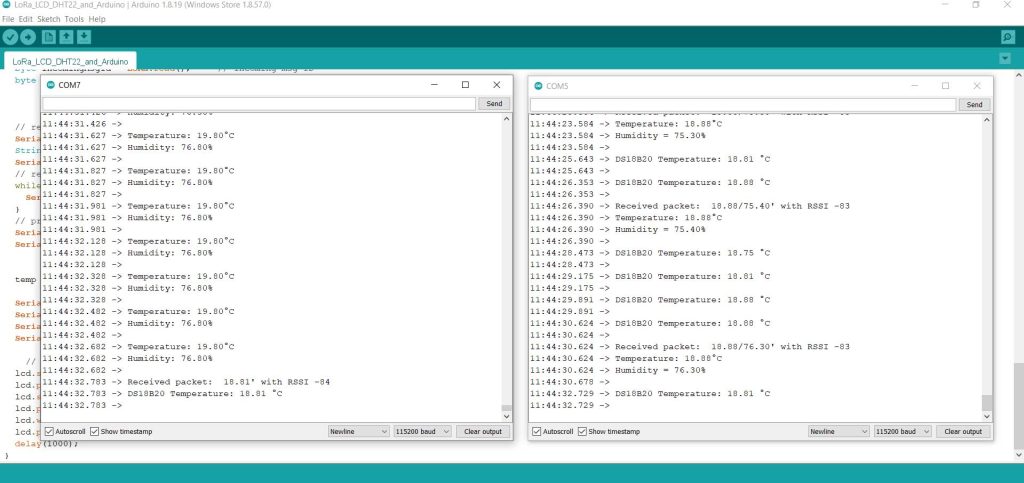
You can see the Live data sent and received by the LoRa module. As we have connected Displays to both Nodes to monitor those data wirelessly using LoRa modules.
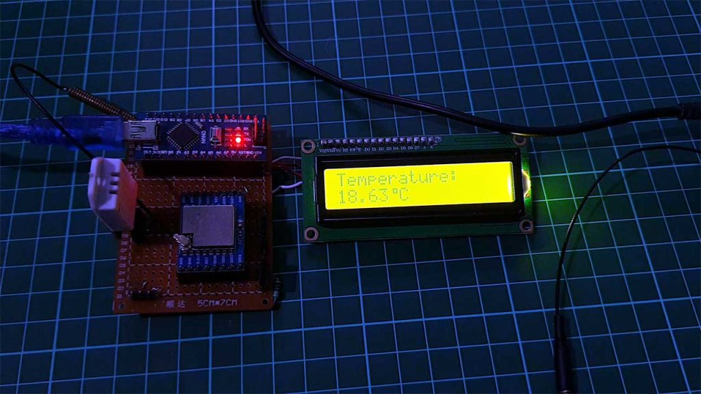
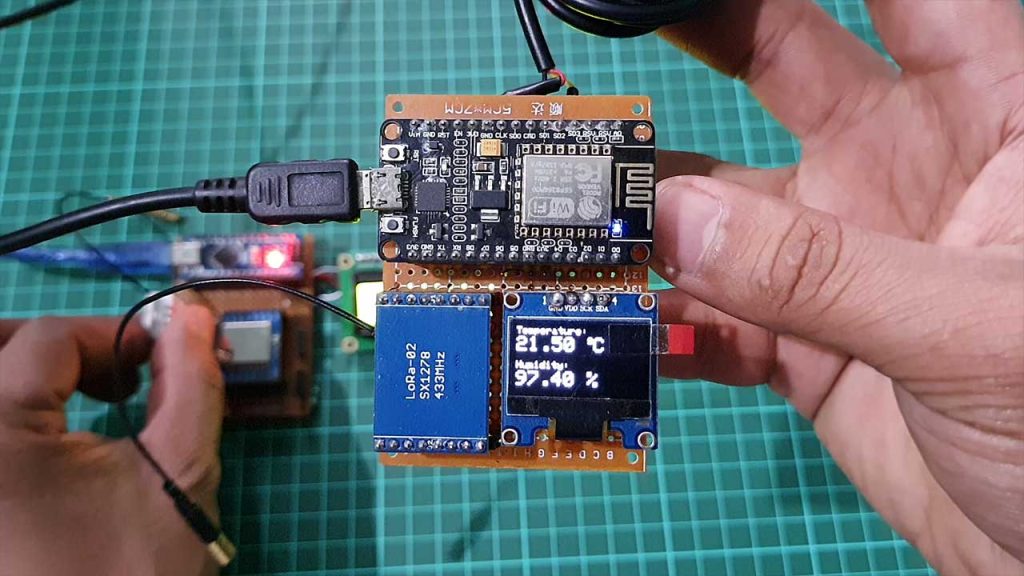
You can monitor DS18B20 temperature data on the Arduino node connected with a 16×2 LCD Display. Whereas you can monitor DHT22 Temperature & Humidity data on ESP8266 Node connected with OLED Display.
Conclusion
So, this is a complete two way wireless communication system using LoRa SX1278 Module and Arduino. I hope the tutorial was helpful for you. In upcoming projects, I will make a network in which the Master Node will request data from the multiple Slave Nodes. Till then stay happy, stay safe.
PCB for LoRa RA-02 and Nano is good but I am expecting few more modifications in the PCB design. It would be good if it has on board 5V regulator IC and dc jack for connecting power adapter. We should be also able to use few important pins of Arduino such as SDA, SCL for connecting I2C LCD or I2C based sensors. It would be better to have expansion for all the pins of Nano so that any pin can be used with jumper wires.