AWS IoT Core With ESP8266 & BME280 Sensor
Sending BME280 Sensor Data to Amazon AWS IoT Core with ESP8266
This is a getting started tutorial about Amazon Web Services, i.e AWS IoT Core with ESP8266. So, today we will learn to interface the BME280 environmental sensor with ESP8266 NodeMCU and monitor the sensor data using AWS IoT Core MQTT broker. The AWS IoT Core is a managed cloud service that lets connected devices easily and securely interact with cloud applications and other devices.
- Overview: Amazon AWS IoT Core with ESP8266
- Components Required
- Hardware Setup/Circuit Diagram
- What is Amazon AWS IoT Core?
- Getting Started with AWS IoT Core with ESP8266
- Installing Necessary Arduino Libraries
- Check the Default I2C address for BME280 Sensor
- Source Code/Program for connecting AWS IoT Core with ESP8266
- Testing the Publishing & Subscription of Data
- Video Tutorial & Guide
Overview: Amazon AWS IoT Core with ESP8266
In this tutorial, we will learn how you can connect the ESP8266 with AWS IoT Core & publish sensor reading to AWS MQTT. We will use the BME280 Sensor for a demo and read the temperature, humidity, barometric pressure, altitude, and dew point data. The ESP8266 will connect to the local WiFi network and post the BME280 Sensor data to AWS IoT Cloud. Not only posting data, but we can also receive the data from AWS Dashboard. This tutorial consists of multiple sections:
- Signing up & setting the Amazon Web Services
- Installing Necessary Libraries to Arduino IDE & Writing an Arduino program for the project
- Creating a Thing in AWS IoT
- Creating Policy and attaching to Thing
- Generating Certificates
- Modifying Arduino Program according to Thing Data & Credentials
- Subscribe & Publish Data to and from AWS IoT Dashboard
This tutorial is for beginners who want to learn about the Amazon AWS IoT Core for IoT Applications. Earlier we learned about IoT platforms like Blynk IoT, Thingspeak and Arduino IoT Cloud. But with AWS IoT Core, you can build and manage devices for commercial applications.
Components Required
The hardware required for this project is an ESP8266 Wifi Module. And for the sensor part, we will use the BME280 Environmental Sensor. Additionally, you will need a few jumper cables and a breadboard for the setup. You can purchase all the components from the link provided below:
| S.N | Components Name | Description | Quantity | |
|---|---|---|---|---|
| 1 | ESP8266 Module | NodeMCU ESP8266 12E Board | 1 | https://amzn.to/3y0zmyq |
| 2 | BME280 | Barometric Pressure Sensor | 1 | https://amzn.to/3Ref7Vd |
| 3 | Jumper Wires | Male to Male Jumper Wires | 4 | https://amzn.to/2JWSR44 |
| 4 | Breadboard | Solderless Breadboard MIni | 1 | https://amzn.to/3n33uRT |
Hardware Setup/Circuit Diagram
Now, Let’s wire the BME280 sensor with the NodeMCU ESP8266. The Connections are fairly simple. Start by connecting the VCC pin to the 3.3V output on the NodeMCU and connect GND to the Ground Pin.
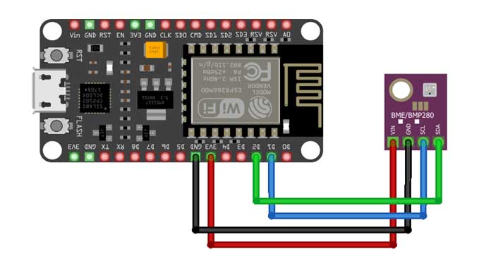
We use now the remaining SCL and SDA pins for I2C communication. Connect the SCL pin to GPIO 05(D1) and the SDA pin to the GPIO 04(D2) pin of the NodeMCU ESP8266 Module, respectively.
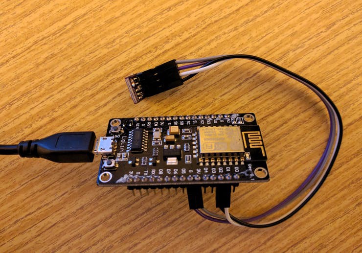
You can use a breadboard for connection or simply use a male-to-female connector wire.
But, I Prefer to order a custom PCB from PCBWay.com. It is a one-stop solution for all your PCB needs like PCB prototyping, SMD stencils, PCB assembly, etc. currently, they are offering 10 pieces of 2 layered PCB at just 5 dollars.
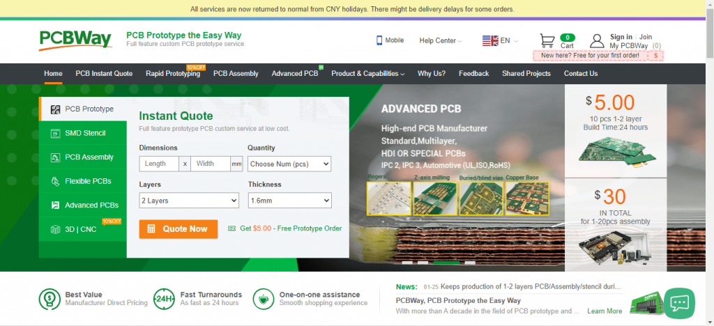
Here I am going to introduce the PCBWAY 8th Anniversary Promotion.
Currently, they are celebrating the 8th Anniversary and giving huge discounts on their products so must avail of all these discounts and promo links to get the required products at good rates. You can go to this link: PCBWAY 8th Anniversary Promotion to get more discounts and offer.

What is Amazon AWS IoT Core?
AWS offers Internet of Things (IoT) services and solutions to connect and manage billions of devices. These cloud services connect your IoT devices to other devices and AWS cloud services. AWS IoT provides device software that can help you integrate your IoT devices into AWS IoT-based solutions. If your devices can connect to AWS IoT, AWS IoT can connect them to the cloud services that AWS provides.
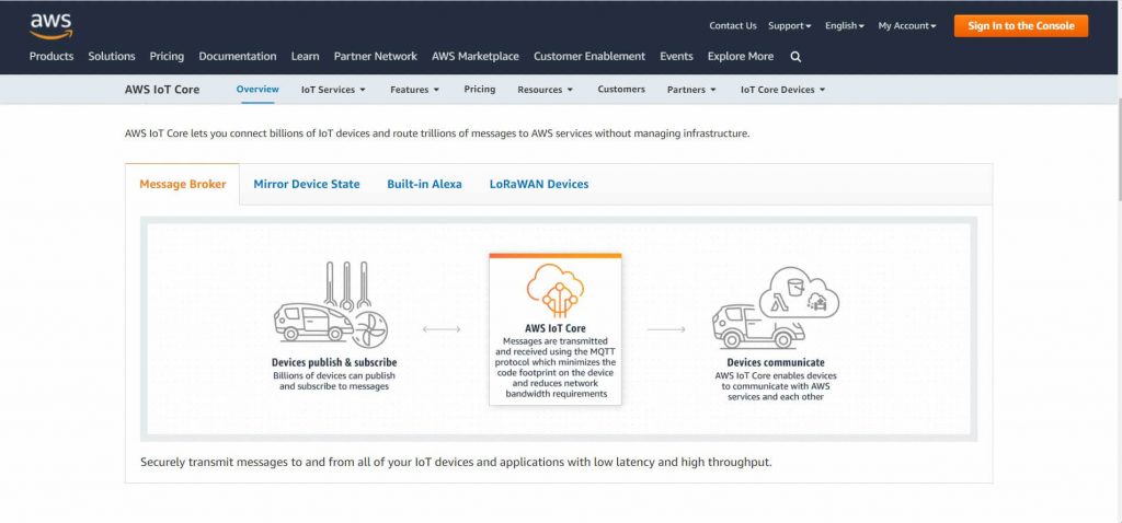
AWS IoT lets you select the most appropriate and up-to-date technologies for your solution. To help you manage and support your IoT devices in the field, AWS IoT Core supports these protocols:
- MQTT (Message Queuing and Telemetry Transport)
- MQTT over WSS (Websockets Secure)
- HTTPS (Hypertext Transfer Protocol – Secure)
- LoRaWAN (Long Range Wide Area Network)
You can learn more about AWS IoT Core in this article.
Getting Started with AWS IoT Core with ESP8266
Getting started with AWS IoT core is very simple. You just need to follow the following steps given below to successfully set up the ESP8266 board and start with your very first project.
Signing in
Go to your web browser and search visit the following link: aws.amazon.com/iot-core/.
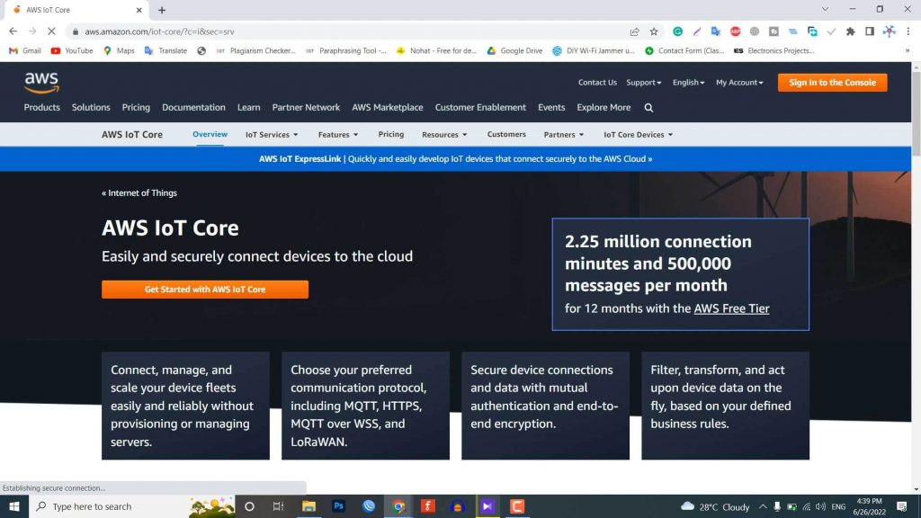
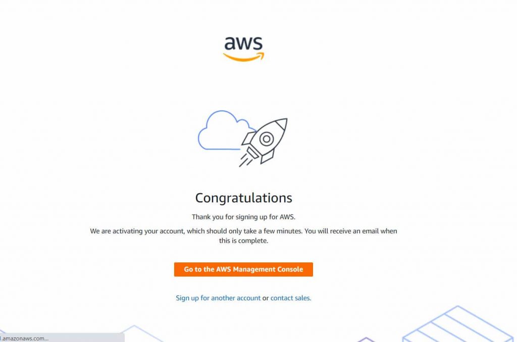
Basically, we need to set up the AWS Account now. Therefore create an account using the email ID and password. The account also requires your bank Credit card information. There will be no charges but AWS just needs a verification using your bank account. It will also ask for phone number verification. Hence the account will be successfully created.
AWS IoT Core Dashboard
After successfully signing in, the AWS Management Console window will open. In the services search tab at the top write ‘IoT core’ & hit enter.
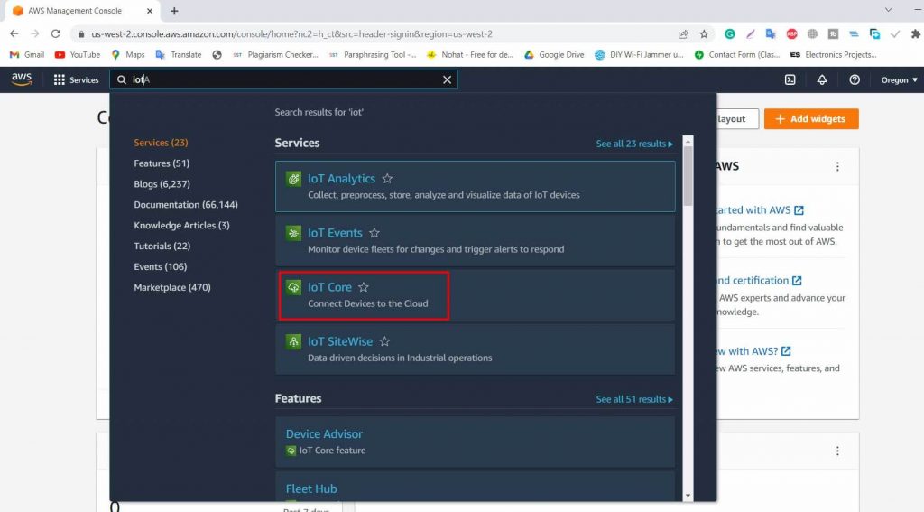
You can click on IoT Core, so an AWS IoT Dashboard will appear now.
On the left side of the dashboard, there are so many options. But we need to work with two options here. One is the All Devices option and the other one is the secure option.
Creating a Thing
Now we need to create a thing associated with our project. For this, follow the following steps:
- Specifying thing properties
- Configuring device certificate
- Attaching policies to the certificate
Under All devices, option-click on Thing. Now we need to create a Thing here. So, click on Create Things here.
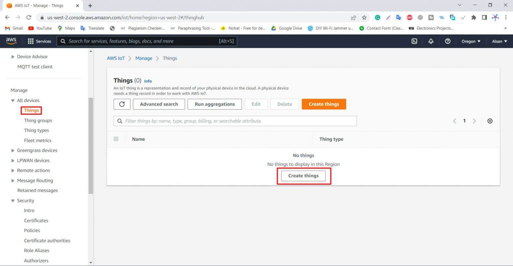
You can select whether create a single thing or create many things. But for our applications, select create a single thing. Then click on Next.
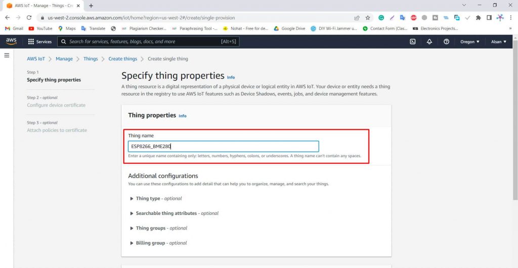
Specify Thing Properties
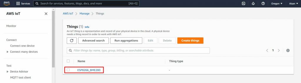
Here we need to specify the Thing properties. First, give a thing name. You can name it anything. For example, I will name it ESP8266_BME280.
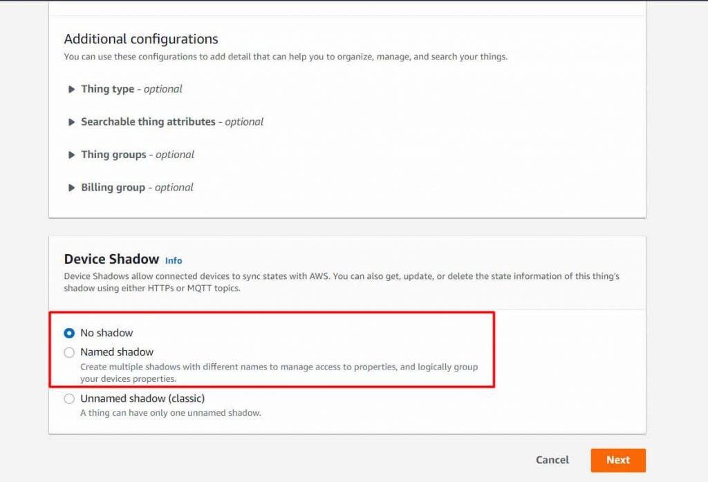
Under additional configurations, there is no need to make any changes.
Under the device shadow option, select the first option as No shadow. Then click on Next.
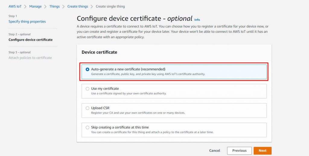
Generate Device Certificate
Now you need to configure the device certificate. So here you can auto-generate a new certificate or use your own certificate or upload CSR or skip this.
But the AWS recommendation is to select the Auto Generate New Certificate. Then click on Next.
Create & Attach Policy
Now we need to attach a policy to the Things we created. But no policies are here right now. So we need to create a policy first.
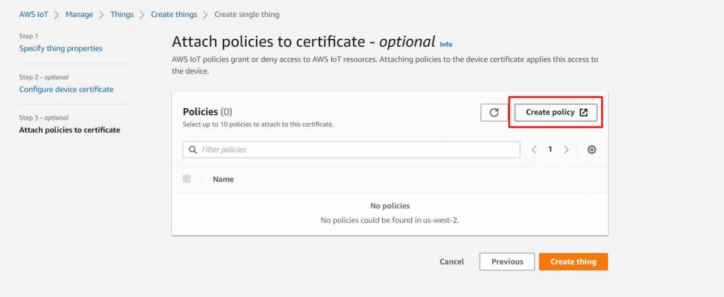
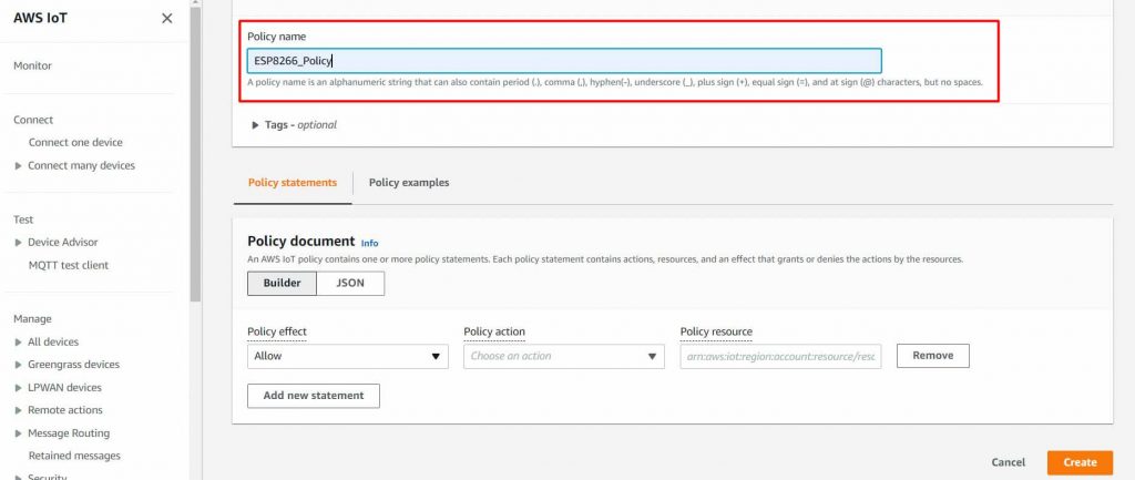
So click on create policy. Here give any name to the policy. For example, I will give it the name “ESP8266_Policy“.
Now the add statement part is very important. Under the policy action, type IoT. So multiple options will pop up. From here we will only need to publish, Subscribe, Connect and Receive.
First, add four statements and select the IoT Connect, IoT Publish, IoT Subscribe, and IoT Receive options. In the Policy Resource type “*” This will allow everything.
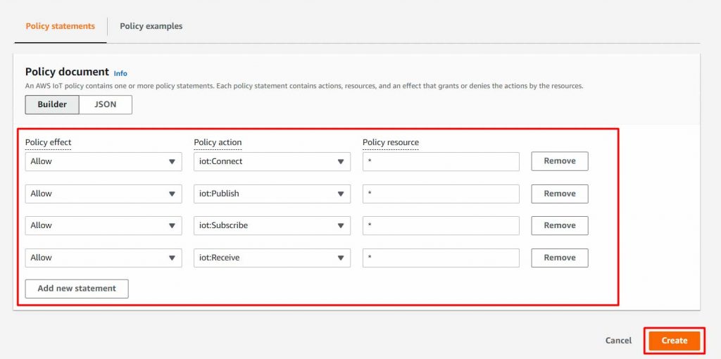
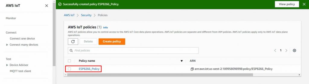
Now click on create to create the policy. So the policy has been created successfully.
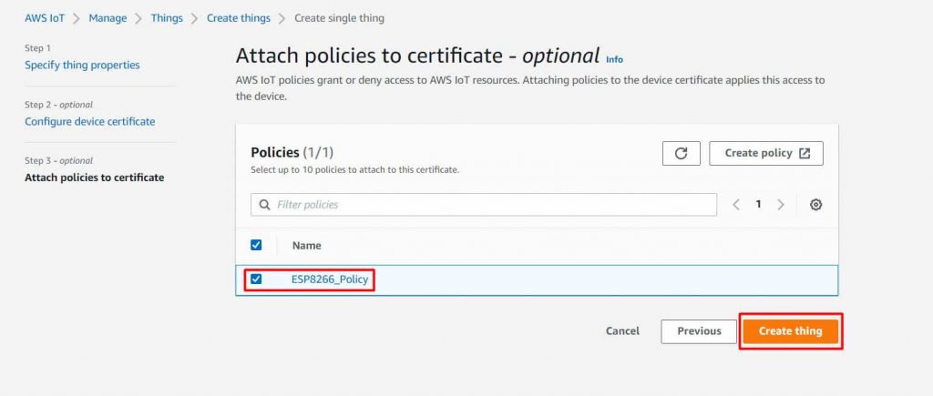
Now go back to Create Thing option. So a policy option will appear. We need to attach the policies to the certificate. So select the appeared policy and click on create a thing.
Downloading Certificates and Keys
Now we need to download the required certificates from this list.
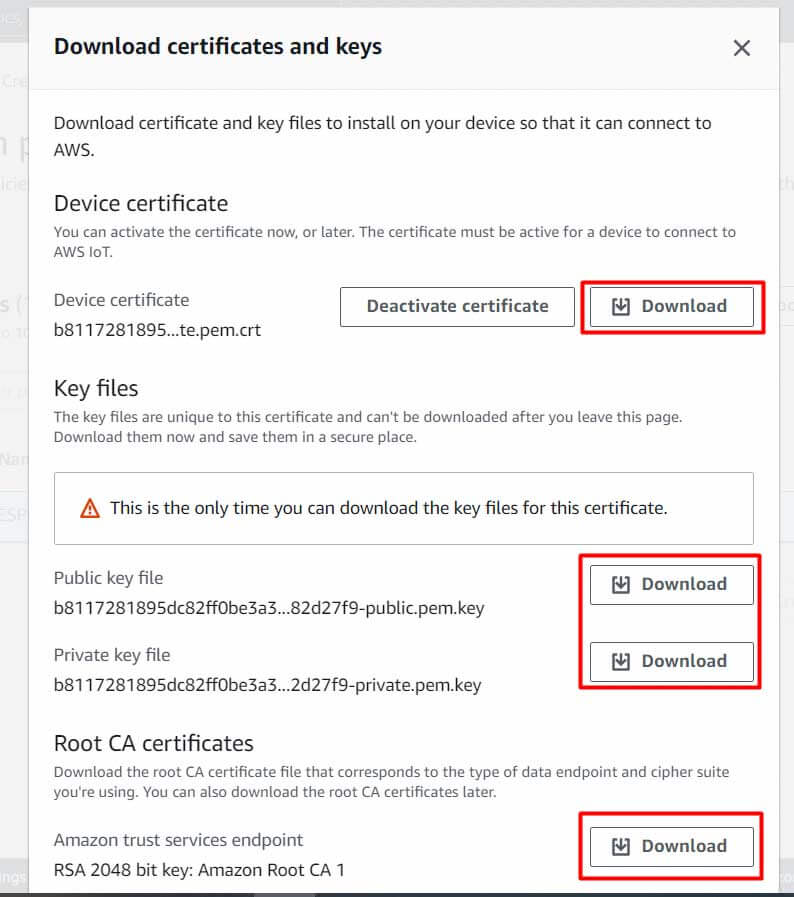
First, download the device certificate and then rename it as a device certificate for identification.
Also, download the public key and rename it as a public key. Then download the private key and rename it as a private key.
In the Root CA Certificates, there are two certificates here. But we just need a Root CA1 certificate, so download it as well.
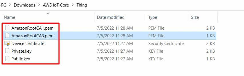
So we have downloaded all the certificates that we need for our project.
Installing Necessary Arduino Libraries
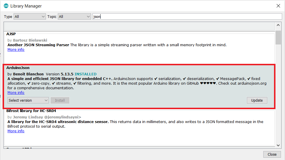
1. ArduinoJSON Library
So first go to the library manager and search for “JSON” & install the library as shown in the figure below.
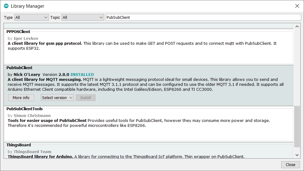
2. PubSubClient Library
Again go to the library manager and search for “PubSubClient” & install the library from Nick O’Leary.
3. BME280 Sensor Library
Search for “Adafruit BME280” & install the library as shown below.

4. Adafruit Unified Sensor Library
Lastly, Install the “Adafruit unified sensor library” as shown below.

Check the Default I2C address for BME280 Sensor
To check the default I2C address of your BME280 sensor with NodeMCU. Simply upload the I2C Address Scanner code provided below. Now, open the serial monitor to check your BME280 default I2C address. This code will also help you to check whether your sensor is working or not.
#include <Wire.h>

void setup() {
  Wire.begin();
  Serial.begin(115200);
  Serial.println("nI2C Scanner");
}

void loop() {
  byte error, address;
  int nDevices;
  Serial.println("Scanning...");
  nDevices = 0;
  for(address = 1; address < 127; address++ ) {
    Wire.beginTransmission(address);
    error = Wire.endTransmission();
    if (error == 0) {
      Serial.print("I2C device found at address 0x");
      if (address<16) {
        Serial.print("0");
      }
      Serial.println(address,HEX);
      nDevices++;
    }
    else if (error==4) {
      Serial.print("Unknow error at address 0x");
      if (address<16) {
        Serial.print("0");
      }
      Serial.println(address,HEX);
    }
  }
  if (nDevices == 0) {
    Serial.println("No I2C devices foundn");
  }
  else {
    Serial.println("donen");
  }
  delay(5000);
}
Source Code/Program for connecting AWS IoT Core with ESP8266
The code/program that interfaces ESP8266 with BME280 Sensor & connects to the Amazon AWS IoT Core is written in Arduino IDE. The code is divided into two sections. One is the source ino file and the other is the header file.
AWS IoT Core with ESP8266.ino file
Open a new sketch in Arduino IDE & paste the following code and save it.
#include <ESP8266WiFi.h>
#include <WiFiClientSecure.h>
#include <PubSubClient.h>
#include <ArduinoJson.h>
#include <time.h>
#include "secrets.h"
#include <Wire.h>
#include <Adafruit_Sensor.h>
#include <Adafruit_BME280.h>

#define SEALEVELPRESSURE_HPA (1013.25)

Adafruit_BME280 bme; // I2C

float temperature;
float humidity;
float pressure;
float altitude;
float dewPoint;

unsigned long lastMillis = 0;
unsigned long previousMillis = 0;
const long interval = 5000;

#define AWS_IOT_PUBLISH_TOPIC   "esp8266/pub"
#define AWS_IOT_SUBSCRIBE_TOPIC "esp8266/sub"

WiFiClientSecure net;

BearSSL::X509List cert(cacert);
BearSSL::X509List client_crt(client_cert);
BearSSL::PrivateKey key(privkey);

PubSubClient client(net);

time_t now;
time_t nowish = 1510592825;


void NTPConnect(void)
{
  Serial.print("Setting time using SNTP");
  configTime(TIME_ZONE * 3600, 0 * 3600, "pool.ntp.org", "time.nist.gov");
  now = time(nullptr);
  while (now < nowish)
  {
    delay(500);
    Serial.print(".");
    now = time(nullptr);
  }
  Serial.println("done!");
  struct tm timeinfo;
  gmtime_r(&now, &timeinfo);
  Serial.print("Current time: ");
  Serial.print(asctime(&timeinfo));
}


void messageReceived(char *topic, byte *payload, unsigned int length)
{
  Serial.print("Received [");
  Serial.print(topic);
  Serial.print("]: ");
  for (int i = 0; i < length; i++)
  {
    Serial.print((char)payload[i]);
  }
  Serial.println();
}


void connectAWS()
{
  delay(3000);
  WiFi.mode(WIFI_STA);
  WiFi.begin(WIFI_SSID, WIFI_PASSWORD);

  Serial.println(String("Attempting to connect to SSID: ") + String(WIFI_SSID));

  while (WiFi.status() != WL_CONNECTED)
  {
    Serial.print(".");
    delay(1000);
  }

  NTPConnect();

  net.setTrustAnchors(&cert);
  net.setClientRSACert(&client_crt, &key);

  client.setServer(MQTT_HOST, 8883);
  client.setCallback(messageReceived);


  Serial.println("Connecting to AWS IOT");

  while (!client.connect(THINGNAME))
  {
    Serial.print(".");
    delay(1000);
  }

  if (!client.connected()) {
    Serial.println("AWS IoT Timeout!");
    return;
  }
  // Subscribe to a topic
  client.subscribe(AWS_IOT_SUBSCRIBE_TOPIC);

  Serial.println("AWS IoT Connected!");
}

void publishMessage()
{
  StaticJsonDocument<200> doc;
  doc["time"] = millis();
  doc["temperature"] =(String(temperature) + String(" °C") );
  doc["humidity"] = (String(humidity) + String(" %") );
  doc["pressure"] = (String(pressure) + String(" hPa") );
  doc["Altitude"] = (String(altitude) + String(" m") );
  doc["DewPoint"] = (String(dewPoint) + String(" °C") );
  char jsonBuffer[512];
  serializeJson(doc, jsonBuffer); // print to client

  client.publish(AWS_IOT_PUBLISH_TOPIC, jsonBuffer);
}


void setup()
{
  Serial.begin(115200);
  connectAWS();
  unsigned status;
  status = bme.begin();
  if (!status) {
    Serial.println("Could not find a valid BME280 sensor, check wiring, address, sensor ID!");
    while (1) delay(10);
  }
}

void loop()
{
  temperature = bme.readTemperature();
  humidity = bme.readHumidity();
  pressure = bme.readPressure() / 100.0F;
  altitude = bme.readAltitude(SEALEVELPRESSURE_HPA);
  dewPoint = dewPointFast(temperature, humidity);

  Serial.print("Temperature = ");
  Serial.print(temperature);
  Serial.println(" °C");

  Serial.print("Humidity = ");
  Serial.print(humidity);
  Serial.println(" %");

  Serial.print("Pressure = ");

  Serial.print(pressure);
  Serial.println(" hPa");

  Serial.print("Approx. Altitude = ");
  Serial.print(altitude);
  Serial.println(" m");

  Serial.print("DewPoint = ");
  Serial.print(dewPoint);
  Serial.println(" °C");


  Serial.println();
  delay(2000);

  now = time(nullptr);

  if (!client.connected())
  {
    connectAWS();
  }
  else
  {
    client.loop();
    if (millis() - lastMillis > 5000)
    {
      lastMillis = millis();
      publishMessage();
    }
  }
}
/*----------DewPoint Calculation--------*/
      double dewPointFast(double celsius, double humidity)
{
  double a = 17.271;
  double b = 237.7;
  double temp = (a * celsius) / (b + celsius) + log(humidity * 0.01);
  double Td = (b * temp) / (a - temp);
  return Td;
}
Secrets.h
Open a New Tab in Arduino IDE and name it as Secrets.h. And paste the following code to this file.
#include <pgmspace.h>

#define SECRET

const char WIFI_SSID[] = "*********";               //WiFi SSID
const char WIFI_PASSWORD[] = "********";           //WiFi Password

#define THINGNAME "********"

int8_t TIME_ZONE = -5; //NYC(USA): -5 UTC

const char MQTT_HOST[] = "********************************";


static const char cacert[] PROGMEM = R"EOF(
-----BEGIN CERTIFICATE-----
-----END CERTIFICATE-----
)EOF";


// Copy contents from XXXXXXXX-certificate.pem.crt here ▼
static const char client_cert[] PROGMEM = R"KEY(
-----BEGIN CERTIFICATE-----
-----END CERTIFICATE-----


)KEY";


// Copy contents from  XXXXXXXX-private.pem.key here ▼
static const char privkey[] PROGMEM = R"KEY(
-----BEGIN RSA PRIVATE KEY-----
-----END RSA PRIVATE KEY-----

)KEY";
Modifying Arduino Sketch according to the Thing
Now it’s time to modify the Arduino Sketch File. Go to secrets.h tab and begin the modification.
Here we need to include a thing name. You can go to the things section of AWS Console and copy the thing name.
Paste the thing name to the following line of code.
#define THINGNAME "********"
Under the WiFi SSID and password, enter the WiFi SSID and Password of your local network.
const char WIFI_SSID[] = "*********";               //WiFi SSID
const char WIFI_PASSWORD[] = "********";           //WiFi Password
Now, we need to insert the AWS IoT Endpoint here. To get the endpoint, go to the settings part of AWS Dashboard. Yow will get the endpoint.
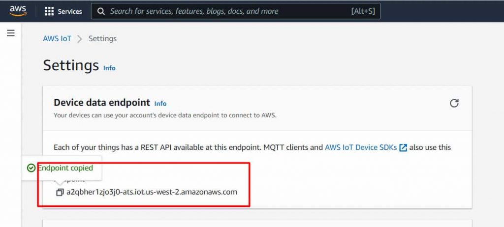
Click on the Copy icon to copy the endpoint. Go back to Arduino IDE and paste it on the following line.
const char MQTT_HOST[] = "********************************";
You need to insert the Amazon Root CA1 in between the following line.
static const char cacert[] PROGMEM = R"EOF(
-----BEGIN CERTIFICATE-----
-----END CERTIFICATE-----
)EOF";
So for this, we need to return to the certificate we downloaded earlier. Open this file with Notepad++ and copy all the text.
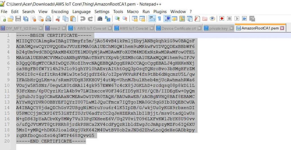
Then go back to Arduino IDE and insert the copied text between begin certificate and the end certificate.
Under the “Device Certificate” lines, we need to paste the device certificate text. So open the device certificate file that we downloaded earlier. And again copy the text and paste it between the begin certificate and end certificate section.
static const char client_cert[] PROGMEM = R"KEY(
-----BEGIN CERTIFICATE-----
-----END CERTIFICATE-----


)KEY";
Under the “Device Private Key“, we need to insert the device’s private key. So go to the downloaded folder again and open the device’s private key file using Notepad++. Again copy the text and paste it between begin & end parts.
static const char privkey[] PROGMEM = R"KEY(
-----BEGIN RSA PRIVATE KEY-----
-----END RSA PRIVATE KEY-----

)KEY";
So all the modification of the Arduino ESP8266 Sketch related to AWS IoT Core is done now.
Testing the Publishing & Subscription of Data
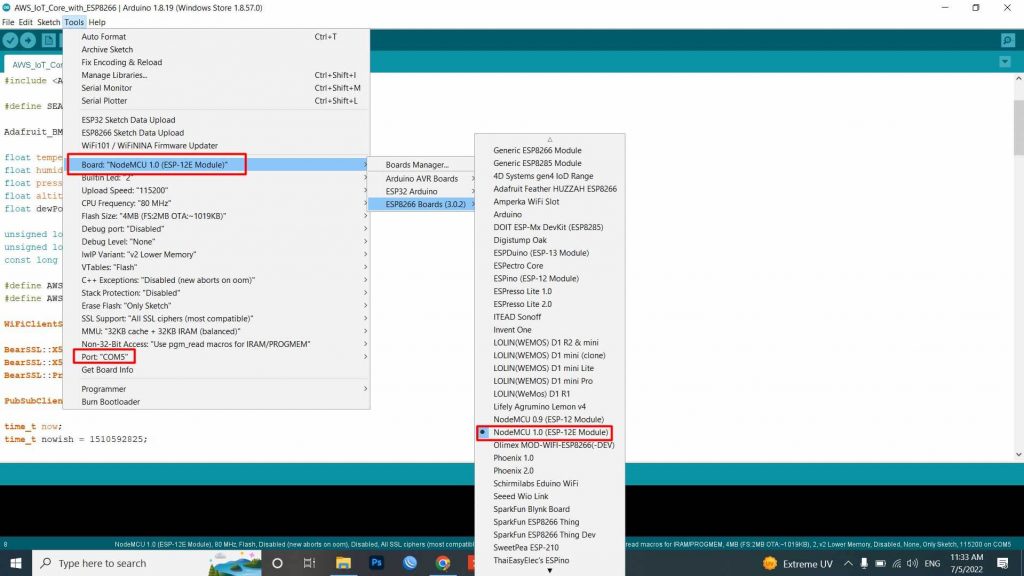
Once all the modification is done, connect the ESP8266 to your computer. Then go to the tools & select ESP8266 Board that you are using for this project. Also, select the COM port. Then click on the upload option to upload the code to the ESP8266 board.
Once the code uploading is done, open the Serial Monitor. The ESP8266 will try connecting to the WiFi Network. Once it gets connected to the WiFi Network, it will try connecting to the AWS IoT Server.
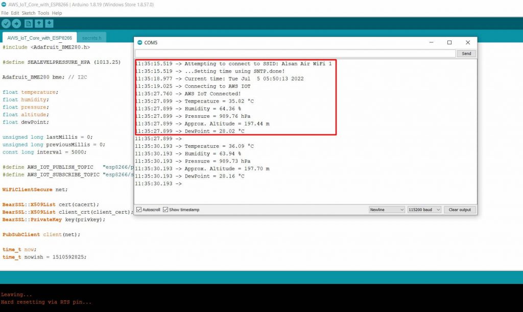
The temperature, humidity, barometric pressure, altitude, and dew point value will appear on the Serial Monitor.
Subscribing Sensor Data to AWS Dashboard
The same thing should also be posted to the AWS Server. To check that, go to the test section of AWS Dashboard. Under the test section, we have an option for subscribing and publishing.
Now to see the data, you need to subscribe to a topic. For that type “esp8266/pub“ under the topic filter section. In the additional configuration, you can make changes if you want.
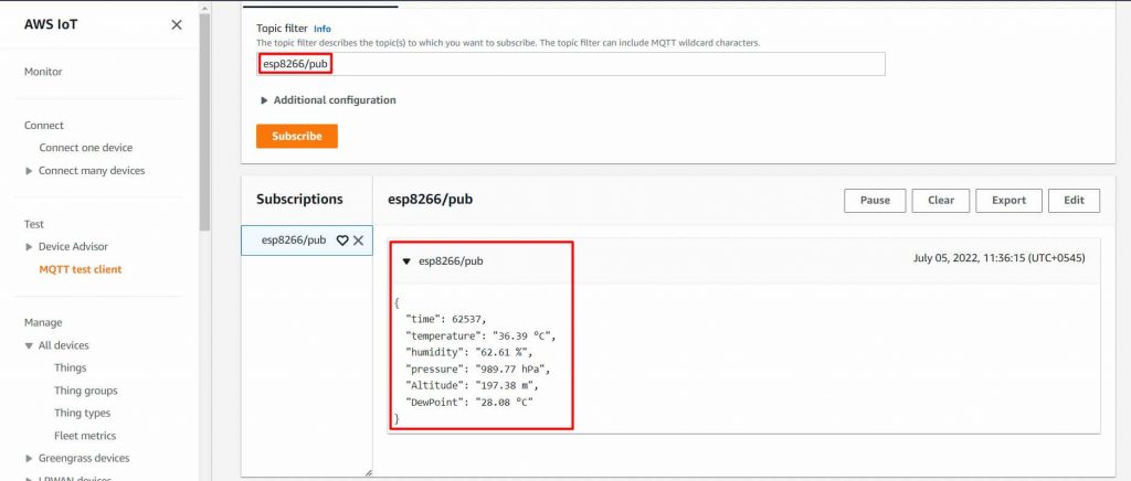
Then click on subscribe. When you hit the subscribe button, immediately the data from ESP8266 will be uploaded to AWS Dashboard. Thus, you have successfully sent the BME280 Sensor data to Amazon AWS IoT Core using ESP8266.
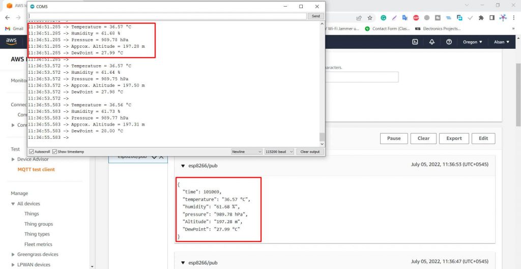
The data is updated here after an interval of every one second. This is really amazing as we are able to receive the data to AWS IoT Core Dashboardsent from ESP8266 via MQTT protocol. This is how we read the subscribed data.
Publishing Data to Serial Monitor
Now let’s see if we are able to publish the data from AWS IoT core to ESP8266 or not.
Now to see the data, you need to publish a topic. For that type “esp8266/sub“ under the topic filter section. Under additional configuration do nothing. Then click on publish.
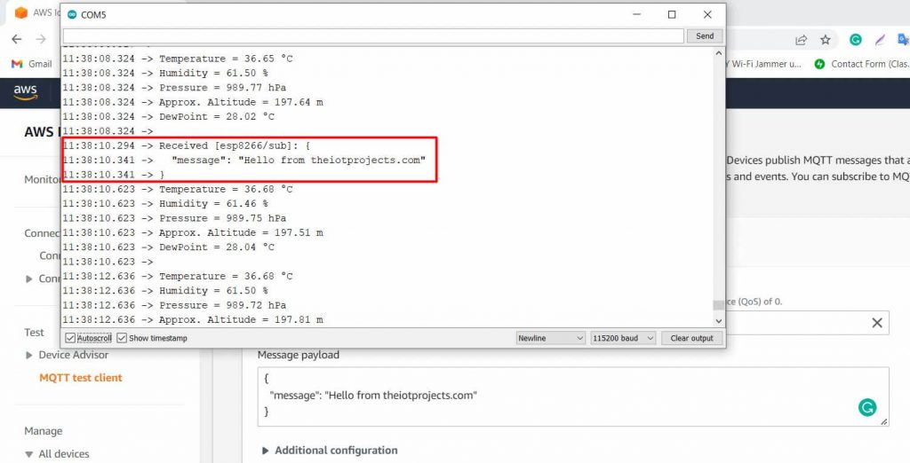
Immediately you can see the message sent to the Serial Monitor. This is amazing again.
You can send or receive data from Amazon AWS IoT Core using ESP8266. Using AWS MQTT, we can subscribe to sensor readings topics published by various IoT nodes. This is a basic beginner’s tutorial for users who want to start with Amazon Web Services for their IoT devices.
Video Tutorial & Guide
I hope this tutorial was useful to you. So, don’t forget to like, share and subscribe to this channel for more amazing content. Thank you.


I am Confuse! It is diffculty. It is not good. I use ESP RMaker is batter.
Wonderful material. Clear steps to integrate with AWS! Keep it up!
Nice tutorial! Thanks but I can see the Publishing Data in my Serial Monitor.
I try the code with ESP32 but didn’t work the BearSSL part, can you help me to migrate it?
Thank you for the tutorial. Clear and concise.