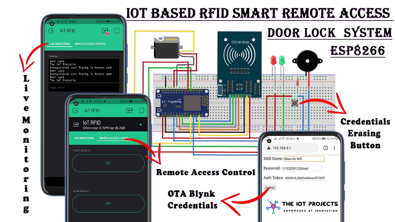
Today in this project you will learn How to make IoT based RFID smart door lock system using NodeMCU ESP8266, RFID MF-RC522 Module, servomotor, and Blynk application. With the help of this project, You can remotely monitor your door lock from anywhere in the world with your phone (Both iPhone and Android Supported).
- Features of IoT based RFID smart door lock system
- Components Requird
- RFID in IoT:
- RFID RC522 Module
- Specifications & Pin Details
- The Working Principle of Servo Motor
- RFID Smart Lock Circuit Diagram
- Configure Blynk App for IoT based RFID smart door lock
- Programming Sketch
- Programming Explanation
- Program Sketch to read UID
- Enter Blink Credential Wirelessly
- Video Tutorial on IoT based RFID smart door lock system using NodeMCU
- Conclusion
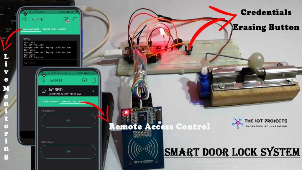
First of all, let’s talk about the app part. Here I have added two tabs. Usually, one for Live Monitoring. Each time user swipes a card a message is received. And another tab is used for remote access control.
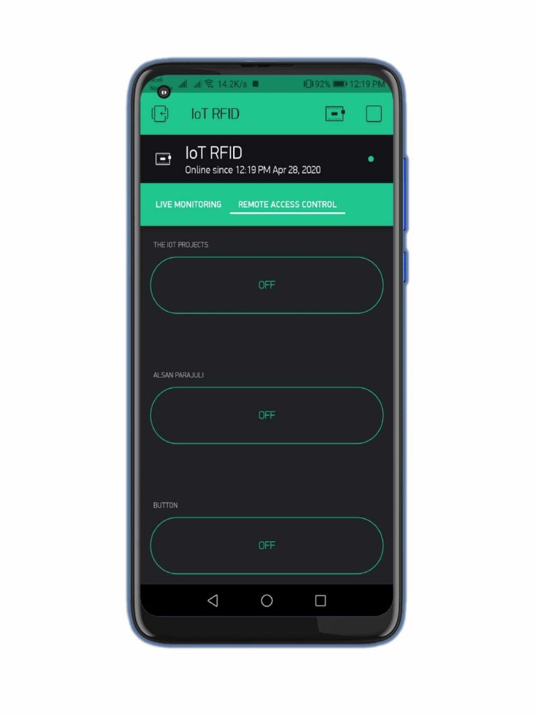
As you can see in the above image all the buttons are turned on. which means admin has given access to all the three users. If the buttons are turned off then users won’t be able to open the door lock.
Features of IoT based RFID smart door lock system
- LEDs as Output response.
- Buzzer to notify with sound
- Over The Air Blynk Credentials (OTABlyankCredentials)
- Erasing Button to Intentionally Erase WiFi Credentials Stored in EEPROM.
- Authorize and Deauthorized Users from anywhere in the world.
- Live Monitor Your Door Lock From your phone.
Projects also have two LEDs. Redone Blink when there is unauthorized access to the smart door lock system. While the Blue LED blink when the Access is granted to the users. Furthermore, a Buzzer is also added so that it produces sound when you have access granted and access denied. In order to open the door lock, the permission should be granted by the Admin. Let’s Grant access to the IoT Projects.
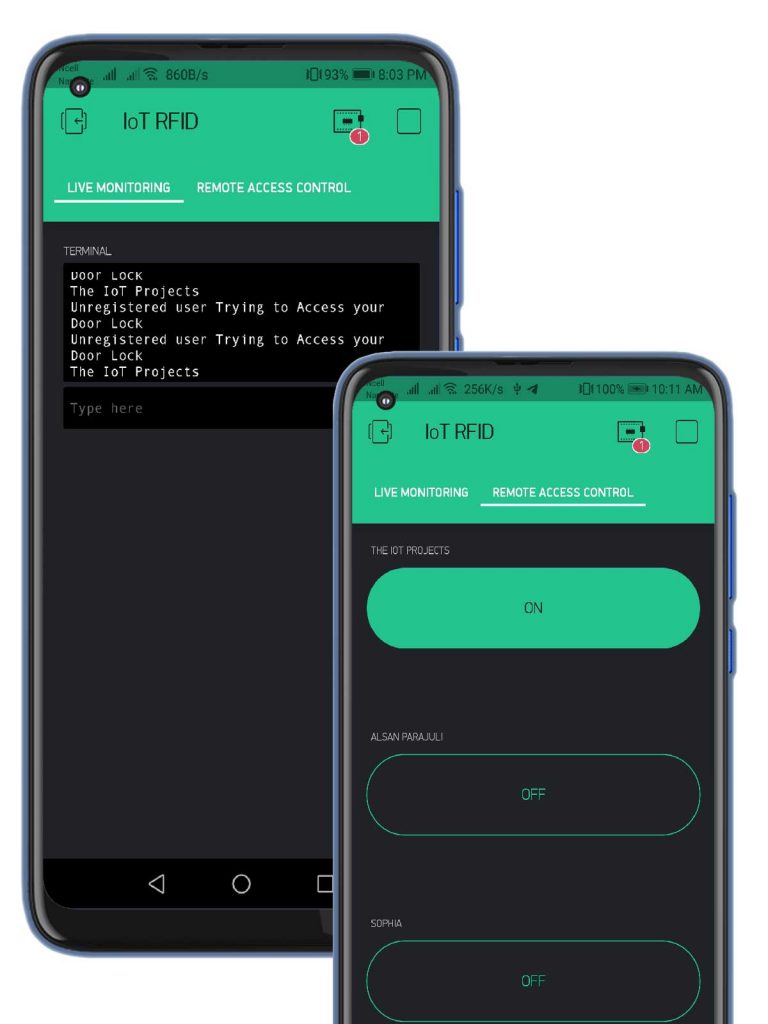
As You can see in the above image, only the IoT Projects can unlock the door lock.
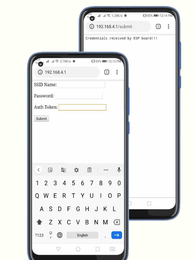
This project has integrated OTABlynkCredentials features. Hence, You can enter WiFi SSID, Password, and Authentication Token Wirelessly using your web browser. Now, you can enter these credentials wirelessly and change them whenever you want without programming the board.
The next important feature is there is a separate button added called the erasing button. which will be used to intentionally erase the wifi credentials stored in it. Sometimes a condition may evolve in your project that you should intentionally erase the WiFi Credentials and Authentication Token inside the NodeMCU Board. Hence, In that case, I have added a separate button. Here, You have to press and hold the button to erase the credentials in it. Hence, you are allowed to enter the new credentials.
Note: For step by step explanation and the practical video demonstration, watch the video tutorial embedded at the end of this article.
In this article, we will cover the MF-RC522 RFID module technical specification and Pinouts. Complete Circuit diagram explanation and Programming code of NodeMCU ESP8266 Board.
Components Requird
The components and tools used in this project are easily available.
- NodeMCU ESP8266 Development Board
- RFID MF-RC522 Module
- Servo SG90 Motor
- Red LED
- Green LED
- Buzzer
- Push Button
- Breadboard
- Jumper Wire
RFID in IoT:
RFID- Radiofrequency identification system is an automatic technology used to identify objects, record metadata, or control individual targets through radio waves. By Connecting RFID reader to the terminal of the Internet, the user can identify, track, and monitor the objects attached with the tags automatically, in real-time from anywhere in the world. Hence we can call it an IoT( Internet of Things. RFID is commonly used by everyone in IoT. When we mixed IoT and RFID technology. we can design so many amazing monitoring and Access control system projects. Through this project, I will allow you to know the use of RFID and IoT tech as well. Basically, applying those two technologies an IoT based RFID smart door lock system using NodeMCU is built.
Here are some more RFID based IoT Projects that we have selected for you.
In this project, I am using RFID with the Nodemcu ESP8266 development board, just to explain How RFID and IoT together can be used to build amazing projects that can be used in real life.
Now before getting started with this project, let’s learn What is RFID? with its specifications and Features.
RFID RC522 Module
What is RFID RC522 Module?
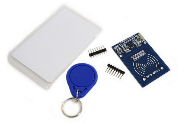
At first, let’s learn a little bit about RFID. RFID is the short form of Radio Frequency Identification. RFID modules use electromagnetic fields for transferring data between the card and the reader. Different RFID tags are attached to objects like Keychain, cards, etc. and whenever we place that object in front of the RFID reader, the reader reads that tags. The next benefit of RFID is that it doesn’t require to be in a straight line to get detected. Unlike a barcode, in RFID there’s no such restriction. So, here are some features of RFID RC522.
Features:
– Module Name: MF522-ED
– Working current:13—26mA/ DC 3.3V
– Standby current:10-13mA/DC 3.3V
– Sleeping current:<80uA
– Peak current:<30mA
– Working frequency:13.56MHz
– Card reading distance :0~60mm(mifare1 card)
– Protocol:SPI
– Data communication speed:Maximum 10Mbit/s
– Card types supported:mifare1 S50、mifare1 S70、 Mifare UltraLight、mifare Pro、 Mifare Desfire
– Dimension:40mm×60mm
– Working temperature:-20—80 degree
– Storage temperature:-40—85 degree
– Humidity:relevant humidity 5%—95%
– Max SPI speed: 10Mbit/s
Specifications & Pin Details
The simple specifications of RC522 module from left to right first pins are as follows:
Pin Name Details
1. 3.3V +3.3V Power Supply
2. RST Reset
3. GND Ground Pin
4. IRO Not Connected
5. MISO Serial Communication
6. MOSI Serial Communication
7. SCK TX/RX with ESP8266
8. SDA TX/RX with ESP8266
The Working Principle of Servo Motor
The servo motor works on the PWM ( Pulse Width Modulation) Principle. This means its angle of rotation is controlled by the duration of the pulse applied to its pulse pins. Basically, the servo motor is made up of DC motor which is controlled by a variable resistor ( Potentiometer) and some gears.
RFID Smart Lock Circuit Diagram
As you can see the circuit diagram is very simple to understand.
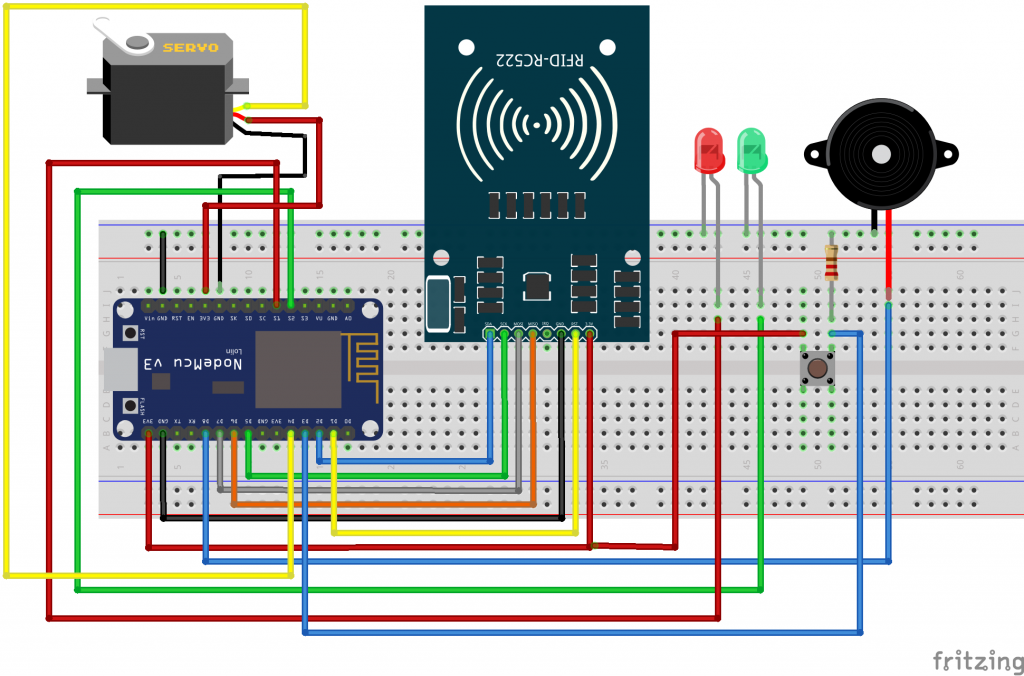
Lets start Interfacing RFID RC522 with NodeMcu ESP8266 Module
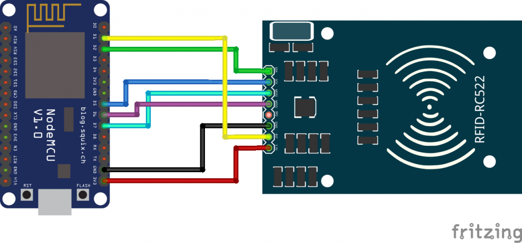
NodeMCU ESP8266/ESP12E RFID MFRC522 / RC522
D2 <———-> SDA/SS
D5 <———-> SCK
D7 <———-> MOSI
D6 <———-> MISO
GND <———-> GND
D1 <———-> RST
3V/3V3 <———-> 3.3V
Interfacing Servo SG90 with NodeMCU
VCC pin/Red Wire to 5volt/ vin pin of NodeMCU.
GND pin/ Black wire to the GND.
Yellow Wire/ Pulse Pin to D4 (GPIO 2)
Similarly, Buzzer Negative Terminal is connected to GND and Positive terminal to D8 Pin of NodeMCU. Now Red and Green both LEDs Negative Pins are Grounded. while the Positive terminal of Red LED is connected to SD3 pin, and Green LED to SD2 Pin of NodeMCU.
we also have added an erasing button, one Pin connected to D3 pin of NodeMCU and Other to the GND through 220-ohm resistor.
Read More: Simple Weather station using Arduino & BME280 Barometric Pressure Sensor
Configure Blynk App for IoT based RFID smart door lock
- – First, log in to your Blynk account. If you don’t have an account then signup with your Gmail.
- – Open the app and create a new project, with the name IoT RFID.
- – Click on the select device and Select NodeMCU.
- – Set the connection Type to WiFi.
- -Finally, click on the create button, an authentication token will be sent to your email. We need this token later.
- – Click on the screen and search for tabs. We are going to add two tabs with the Name Live Monitoring and Remote Access Control.
- – Now click on the live monitoring tab and tap anywhere in the blank space. add the terminal widget. set the terminal widget Virtual pin V2 and set the New Line to Yes.
- -Now Select the Remote Access Control tab. Click on empty space and add three buttons.
- -Click on the First Button, set the Name, and select the virtual Pin V3. Set the button Mode as Switch. You can also set the fonts as per your requirements.
- -Now click on the second button. Set the name, select virtual pin V4, and select button mode as a switch.
- -Similarly, do the same for the third button and set the virtual pin to v5.
Note: In this project, I have added three users The IoT Projects, Alsan Parajuli, and Sophia.
If you still don’t understand then watch my video embedded in the last section of this article.
You may also like: Introduction to The Internet Of Things (IoT)
Programming Sketch
Before you start the programming, first of all, make sure you have downloaded all the necessary libraries.
Download Program Sketch Zip File
Here are the Top 10 IoT (Internet of Things) Projects that we have selected for you.
Note: Place all the files under the samme folder.
IoT based RFID smart door lock system using NodeMCU.ino
#include "OTABlynkCredentials.h"

#ifdef ESP8266
#include <BlynkSimpleEsp8266.h>
#elif defined(ESP32)
#include <BlynkSimpleEsp32.h>
#else
#error "Board not found"
#endif
#include <SPI.h>
#include <MFRC522.h>
#include <Servo.h>
#define BLYNK_PRINT Serial
credentials Credentials;


//Variables
char auth_token[33];
bool connected_to_internet = 0;
const int Erasing_button = 0; // D3 NodeMCU Pin


//Provide credentials for your ESP server
char* esp_ssid = "IoT";
char* esp_pass = "";

#define SS_PIN 4
#define RST_PIN 5
#define LED_G 9 //define green LED pin
#define LED_R 10 //define red LED
#define BUZZER 15 //buzzer pin
MFRC522 mfrc522(SS_PIN, RST_PIN);   // Create MFRC522 instance.
Servo myServo; //define servo name

SimpleTimer timer;
int fflag = 0;
int eflag = 0;
int jflag = 0;
WidgetTerminal terminal(V2);

void setup()

{

  Serial.begin(115200);
  pinMode(Erasing_button, INPUT);


  for (uint8_t t = 4; t > 0; t--) {
    Serial.println(t);
    delay(1000);
  }

  // Press and hold the button to erase all the credentials
  if (digitalRead(Erasing_button) == LOW)
  {
    Credentials.Erase_eeprom();

  }

  String auth_string = Credentials.EEPROM_Config();
  auth_string.toCharArray(auth_token, 33);

  if (Credentials.credentials_get())
  {

    Blynk.config(auth_token);
    connected_to_internet = 1;

  }
  else
  {
    Credentials.setupAP(esp_ssid, esp_pass);
    connected_to_internet = 0;
  }
  if (connected_to_internet)
  {
  SPI.begin();      // Initiate  SPI bus
  mfrc522.PCD_Init();   // Initiate MFRC522 RFID
  myServo.attach(2); //servo pin D4
  myServo.write(0); //servo start position
  pinMode(LED_G, OUTPUT);
  pinMode(LED_R, OUTPUT);
  pinMode(BUZZER, OUTPUT);
  noTone(BUZZER);
  Serial.println("Place your card on the reader...");
  Serial.println();
  timer.setInterval(1000L, iot_rfid);
  }
}

void loop()
{
  Credentials.server_loops();

  if (connected_to_internet)
  {


   timer.run(); // Initiates SimpleTimer
Blynk.run();
}
}
void iot_rfid()
{
  // Look for new cards
  if ( ! mfrc522.PICC_IsNewCardPresent())
  {
    return;
  }
  // Select one of the cards
  if ( ! mfrc522.PICC_ReadCardSerial())
  {
    return;
  }
  //Show UID on serial monitor
  Serial.print("UID tag :");
  String content= "";
  byte letter;
  for (byte i = 0; i < mfrc522.uid.size; i++)
  {
     Serial.print(mfrc522.uid.uidByte[i] < 0x10 ? " 0" : " ");
     Serial.print(mfrc522.uid.uidByte[i], DEC);
     content.concat(String(mfrc522.uid.uidByte[i] < 0x10 ? " 0" : " "));
     content.concat(String(mfrc522.uid.uidByte[i], DEC));
  }
  Serial.println();
  Serial.print("Message : ");
  content.toUpperCase();
  // defining cards here
  if( (content.substring(1) == "134 96 128 248") && (fflag == 1) ) //change the UID of the card/cards that you want to give access
  {
    Serial.println("The IoT Projects");
    Blynk.virtualWrite(V2, "The IoT Projects" );
    Serial.println();
    delay(500);
    digitalWrite(LED_G, HIGH);
    tone(BUZZER, 500);
    delay(250);
    noTone(BUZZER);
    myServo.write(180);
    delay(3000);
    myServo.write(25);
    digitalWrite(LED_G, LOW);
  }
 else
 if( (content.substring(1) == "129 163 220 121") && (eflag == 1) ) //change the UID of the card/cards that you want to give access
  {
    Serial.println("Alsan Parajuli");
    Blynk.virtualWrite(V2, "Alsan Parajuli" );
    Serial.println();
    delay(500);
    digitalWrite(LED_G, HIGH);
    tone(BUZZER, 500);
    delay(250);
    noTone(BUZZER);
    myServo.write(180);
    delay(3000);
    myServo.write(25);
    digitalWrite(LED_G, LOW);
  }
  else
 if( (content.substring(1) == "57 234 176 109") && (jflag == 1) ) //change the UID of the card/cards that you want to give access
  {
    Serial.println("Sophia");
    Blynk.virtualWrite(V2, "Sophia " );
    Serial.println();
    delay(500);
    digitalWrite(LED_G, HIGH);
    tone(BUZZER, 500);
    delay(250);
    noTone(BUZZER);
    myServo.write(180);
    delay(3000);
    myServo.write(25);
    digitalWrite(LED_G, LOW);
  }
 else   {
    Serial.println("unregistered user");
    Blynk.virtualWrite(V2, "Unregistered user Trying to Access your Door Lock " );
    Serial.println(" Access denied");
    digitalWrite(LED_R, HIGH);
    tone(BUZZER, 300);
    delay(1500);
    digitalWrite(LED_R, LOW);
    noTone(BUZZER);
  }
}
// in Blynk app writes values to the Virtual Pin 3
BLYNK_WRITE(V3)
{
   fflag = param.asInt(); // assigning incoming value from pin V3 to a variable
  // Blynk.virtualWrite(V2, fflag );

}


// in Blynk app writes values to the Virtual Pin 4
BLYNK_WRITE(V4)
{
   eflag = param.asInt(); // assigning incoming value from pin V4 to a variable

}

BLYNK_WRITE(V5)
{
   jflag = param.asInt(); // assigning incoming value from pin V5 to a variable

}
OTABlynkCredentials.cpp
/*!
   file OTABlynkCredentials.h

 *
 * This code is made for entering WiFi and Blynk Credentials
 * Over the Air using your web browser.
 *
 *
 * Written by Sachin Soni with
 * contributions from the open-source community.
 *
 */

*/


#include "Arduino.h"
#include "OTABlynkCredentials.h"

AsyncWebServer server(80); // Creating WebServer at port 80
WebSocketsServer webSocket = WebSocketsServer(81); // Creating WebSocket Server at port81

//
// This is the webpage which is hosted on your ESP board
// and you can access this webpage by going to this address
//
//                    192.168.4.1
//

char _webpage[] PROGMEM = R"=====(
<html>
  <head>
    <script>
var connection = new WebSocket('ws://'+location.hostname+':81/');

connection.onopen = function ()
{
connection.send('Connect ' + new Date()); };
 connection.onerror = function (error)
 {
  console.log('WebSocket Error ', error);
 };
 connection.onmessage = function (e)
  {
    console.log('Server: ', e.data);
  };

  function credentials_rec()
{

  var ssid = document.getElementById('ssid_cred').value;
  var pass = document.getElementById('pass_cred').value;
  var auth = document.getElementById('auth_token').value;
  var full_command = '#{"ssid":"'+ ssid +'", "pass":"' +pass +'","auth":"'+ auth +'"}';
  console.log(full_command);
  connection.send(full_command);
  location.replace('http://'+location.hostname+'/submit');
}


  </script

  </head>
  <body>
  <label for="ssid_cred">SSID Name:</label>
  <input type="text" id="ssid_cred"><br><br>
  <label for="pass_cred">Password:</label>
  <input type="text" id="pass_cred"><br><br>
  <lable for="auth_token">Auth Token:</label>
  <input type="text" id="auth_token"><br><br>
   <button type="button" onclick=credentials_rec();>Submit</button>

</body>

</html>


)=====";


void _webSocketEvent(uint8_t num, WStype_t type, uint8_t * payload, size_t length)
{

  switch (type) {
    case WStype_DISCONNECTED:
      Serial.printf("[%u] Disconnected!n", num);
      break;
    case WStype_CONNECTED: {
        IPAddress ip = webSocket.remoteIP(num);
        Serial.printf("[%u] Connected from %d.%d.%d.%d url: %sn", num, ip[0], ip[1], ip[2], ip[3], payload);

        // send message to client
        webSocket.sendTXT(num, "Connected");
      }
      break;
    case WStype_TEXT:
      Serial.printf("[%u] get Text: %sn", num, payload);

      if (payload[0] == '#')
      {
        String message = String((char*)( payload));
        message = message.substring(1);
        Serial.println(message);

        //JSON part
        DynamicJsonDocument doc(1024);
        DeserializationError error = deserializeJson(doc, message);

        String ssid = doc["ssid"];
        String pass = doc["pass"];
        String auth = doc["auth"];
        Serial.println(ssid); Serial.println(pass);


        // Clearing EEPROM
        if (ssid.length() > 0 && pass.length() > 0) {
          Serial.println("clearing eeprom");
          for (int i = 0; i < 100; ++i) {
            EEPROM.write(i, 0);
          }


          // Storing in EEPROM
          Serial.println("writing eeprom ssid:");
          for (int i = 0; i < ssid.length(); ++i)
          {
            EEPROM.write(i, ssid[i]);
            Serial.print("Wrote: ");
            Serial.println(ssid[i]);
          }
          Serial.println("writing eeprom pass:");
          for (int i = 0; i < pass.length(); ++i)
          {
            EEPROM.write(32 + i, pass[i]);
            Serial.print("Wrote: ");
            Serial.println(pass[i]);
          }
          Serial.println("writing eeprom auth token:");
          for (int i = 0; i < auth.length(); ++i)
          {
            EEPROM.write(64 + i, auth[i]);
            Serial.print("Wrote: ");
            Serial.println(auth[i]);
          }
          EEPROM.commit();
          delay(2000);

          //Restarting ESP board
          ESP.restart();
          break;
        }
     }
  }
}


void credentials::Erase_eeprom()
{
  EEPROM.begin(512); //Initialasing EEPROM
  Serial.println("Erasing...");
  Serial.println("clearing eeprom");
    for (int i = 0; i < 100; ++i)
    {
      EEPROM.write(i, 0);
    }
   EEPROM.commit();
}


String credentials::EEPROM_Config()
{
 EEPROM.begin(512); //Initialasing EEPROM
  Serial.println();
  Serial.println();

  //---------------------------------------- Read EEPROM for ssid and pass
  Serial.println("Reading EEPROM");


  for (int i = 0; i < 32; ++i)
  {
    ssid += char(EEPROM.read(i));
  }
  Serial.print("SSID: ");
  Serial.println(ssid);

  for (int i = 32; i < 64; ++i)
  {
    pass += char(EEPROM.read(i));
  }

  Serial.print("Password: ");
  Serial.println(pass);
  String auth_token = "";
  for (int i = 64; i < 100; ++i)
  {
    auth_token += char(EEPROM.read(i));
  }
  Serial.print("Auth Token: ");
  Serial.println(auth_token);
  return auth_token;
}


bool credentials::credentials_get()
{
  if (_testWifi())
  {
    Serial.println("Succesfully Connected!!!");
    return true;
  }
  else
  {
    Serial.println("Turning the HotSpot On");
    return false;
  }
}


void credentials::setupAP(char* softap_ssid, char* softap_pass)
{

  WiFi.disconnect();
  delay(100);
  WiFi.softAP(softap_ssid,softap_pass);
  Serial.println("softap");
  _launchWeb();
  Serial.println("Server Started");
   webSocket.begin();
    webSocket.onEvent(_webSocketEvent);
}


bool credentials::_testWifi()
{
  int c = 0;
  Serial.println("Waiting for Wifi to connect");
  char* my_ssid = &ssid[0];
  char* my_pass = &pass[0];

  WiFi.begin(my_ssid, my_pass);
  while ( c < 20 ) {
    if (WiFi.status() == WL_CONNECTED)
    {
      return true;
    }
    delay(500);
    Serial.print("*");
    c++;
  }
  Serial.println("");
  Serial.println("Connect timed out, opening AP");
  return false;
}


// This is the function which will be called when an invalid page is called from client
void notFound(AsyncWebServerRequest *request)
{
  request->send(404, "text/plain", "Not found");
}


void credentials::_createWebServer()
{
server.on("/", [](AsyncWebServerRequest * request) {
  request->send_P(200, "text/html", _webpage);
});

// Send a GET request to <IP>/get?message=<message>
server.on("/submit", HTTP_GET, [] (AsyncWebServerRequest * request) {
  String message;
    message = "Credentials received by ESP board!!!";
   request->send(200, "text/plain", message);
});

server.onNotFound(notFound);
server.begin();

}

void credentials::_launchWeb()
{
  Serial.println("");
  Serial.print("SoftAP IP: ");
  Serial.println(WiFi.softAPIP());
  _createWebServer();
  // Start the server

}

void credentials::server_loops()
{
     webSocket.loop();
}
OTABlynkCredentials.h
/*!
 * file OTABlynkCredentials.h
 *
 * This code is made for entering WiFi and Blynk Credentials
 * Over the Air using your web browser.
 *
 *
 * Written by Sachin Soni with
 * contributions from the open-source community.
 *
 */


#ifdef ESP8266
#include <ESP8266WiFi.h>
#elif defined(ESP32)
#include <WiFi.h>
#else
#error "Board not found"
#endif

#include "Arduino.h"

//
//
//  Install these all libraries to make the project work.
//
//
#include <ESPAsyncWebServer.h>
#include <WebSocketsServer.h>
#include <ArduinoJson.h>
#include <EEPROM.h>


class credentials {
  public:
  bool credentials_get();
  void setupAP(char* softap_ssid, char* softap_pass);
  void server_loops();
  String EEPROM_Config();
  void Erase_eeprom();
  private:
  bool _testWifi(void);
  void _launchWeb(void);
  void _createWebServer(void);
  String ssid = "";
  String pass = "";
};
Programming Explanation
So at first, I started by including the libraries needed for IoT based RFID smart door lock system.
#include <ESPAsyncWebServer.h>
#include <WebSocketsServer.h>
#include <ArduinoJson.h>
#include <EEPROM.h>
#include <SPI.h>
#include <MFRC522.h>
#include <Servo.h>
#define BLYNK_PRINT Serial
The program is compatible with both ESP32 and NodeMCU Board. Here I have applied the condition to use the specific library for specific ESP boards.
#ifdef ESP8266
#include <ESP8266WiFi.h>
#elif defined(ESP32)
#include <WiFi.h>
#else
#error "Board not found"
#endif
For Erasing WiFi and Authentication Token credentials, I have added Erasing Button to D3 (GOIO 0) pin of ESP board.
const int Erasing_button = 0; // D3 NodeMCU PinNow using this code you can make your ESP board as Access Point to receive the required credentials from the user using WebSocket server.
//Provide credentials for your ESP server
char* esp_ssid = "IoT";
char* esp_pass = "";
Define SS and RST Pin of RFID.
#define SS_PIN 4
#define RST_PIN 5
Define Green LED, RED LED, and Buzzer Pin.
#define LED_G 9 //define green LED pin
#define LED_R 10 //define red LED
#define BUZZER 15 //buzzer pin
Create RFID Instance.
MFRC522 mfrc522(SS_PIN, RST_PIN); // Create MFRC522 instance.
MyServo is defined as servo name.
Servo myServo; //define servo nameI have defined a timer here. fflag, eflag, and jflag are the integer type variable. All the flags are assigned to 0. This means by default the user has no access to the door lock. Hence the flag value can be 0 and 1. 0 means no access and 1 means access is granted to the user.
SimpleTimer timer;
int fflag = 0;
int eflag = 0;
int jflag = 0;
The Terminal widget is assigned to the virtual Pin V2.
WidgetTerminal terminal(V2);Inside void setup serial communication is activated at 115200 baudrate for debugging purpose.
pinMode(Erasing_button, INPUT);PinMode function is used for Erasing Button as a Input.
Serial.begin(115200);Now here is simple logic. when the button is pressed fo 4 seconds. It will call credentials.erase_EEPROm function. Else, It will execute the EEPROM Read function to read the required credentials from the EEPROM.
 for (uint8_t t = 4; t > 0; t--) {
    Serial.println(t);
    delay(1000);
  }

  // Press and hold the button to erase all the credentials
  if (digitalRead(Erasing_button) == LOW)
  {
    Credentials.Erase_eeprom();

  }

  String auth_string = Credentials.EEPROM_Config();
  auth_string.toCharArray(auth_token, 33);

  if (Credentials.credentials_get())
  {

    Blynk.config(auth_token);
    connected_to_internet = 1;

  }
  else
  {
    Credentials.setupAP(esp_ssid, esp_pass);
    connected_to_internet = 0;
  }
SPI bus and RFID reader is initiated.
 SPI.begin();      // Initiate  SPI bus
  mfrc522.PCD_Init();   // Initiate MFRC522 RFID
Servo pulse pin is defined to Gpio D4 pin.
myServo.attach(2); //servo pin D4LEDs and Buzzer are used as output.
pinMode(LED_G, OUTPUT);
  pinMode(LED_R, OUTPUT);
  pinMode(BUZZER, OUTPUT);
  noTone(BUZZER);
IoT_RFID is a user-defined function that is executed after every 1 second. Using this Timer.setinterval function.
timer.setInterval(1000L, iot_rfid);In the loop section timer.run and Blynk.run function is initiated.
 timer.run(); // Initiates SimpleTimer
Blynk.run();
In this void iot_rfid( ) user-defined function. we read the RFID card, select the card and then Print the UID in the serial monitor.
// Look for new cards
  if ( ! mfrc522.PICC_IsNewCardPresent())
  {
    return;
  }
  // Select one of the cards
  if ( ! mfrc522.PICC_ReadCardSerial())
  {
    return;
  }
  //Show UID on serial monitor
  Serial.print("UID tag :");
  String content= "";
  byte letter;
  for (byte i = 0; i < mfrc522.uid.size; i++)
  {
     Serial.print(mfrc522.uid.uidByte[i] < 0x10 ? " 0" : " ");
     Serial.print(mfrc522.uid.uidByte[i], DEC);
     content.concat(String(mfrc522.uid.uidByte[i] < 0x10 ? " 0" : " "));
     content.concat(String(mfrc522.uid.uidByte[i], DEC));
  }
  Serial.println();
  Serial.print("Message : ");
  content.toUpperCase();
The main logic behind this project is here. If the RFID identification matches the provided number and flag value is equal to 1, then only it will send a message to the serial monitor and Blynk Virtual Terminal for Live monitoring. with the delay of 500 milliseconds, the green LED is turned on. The buzzer will produce a beep sound. meanwhile, the servo turns to 180 degrees to open the lock. after the delay of 3 seconds, the door is automatically locked. You can change the servo delay value according to your requirements. For the demonstration, I am using a delay of 3 seconds.
// defining cards here
  if( (content.substring(1) == "134 96 128 248") && (fflag == 1) ) //change the UID of the card/cards that you want to give access
  {
    Serial.println("The IoT Projects");
    Blynk.virtualWrite(V2, "The IoT Projects" );
    Serial.println();
    delay(500);
    digitalWrite(LED_G, HIGH);
    tone(BUZZER, 500);
    delay(250);
    noTone(BUZZER);
    myServo.write(180);
    delay(3000);
    myServo.write(25);
    digitalWrite(LED_G, LOW);
  }
Similarly, the same condition is applied to two more cards. You can add as many cards as you want. using this If …. else statement.
else
 if( (content.substring(1) == "129 163 220 121") && (eflag == 1) ) //change the UID of the card/cards that you want to give access
  {
    Serial.println("Alsan Parajuli");
    Blynk.virtualWrite(V2, "Alsan Parajuli" );
    Serial.println();
    delay(500);
    digitalWrite(LED_G, HIGH);
    tone(BUZZER, 500);
    delay(250);
    noTone(BUZZER);
    myServo.write(180);
    delay(3000);
    myServo.write(25);
    digitalWrite(LED_G, LOW);
  }
  else
 if( (content.substring(1) == "57 234 176 109") && (jflag == 1) ) //change the UID of the card/cards that you want to give access
  {
    Serial.println("Sophia");
    Blynk.virtualWrite(V2, "Sophia " );
    Serial.println();
    delay(500);
    digitalWrite(LED_G, HIGH);
    tone(BUZZER, 500);
    delay(250);
    noTone(BUZZER);
    myServo.write(180);
    delay(3000);
    myServo.write(25);
    digitalWrite(LED_G, LOW);
  }
Now, when either of the conditions becomes false then else statement is executed. This will print the Access denied message to the serial Monitor as well as the Blynk virtual terminal. After that a red led will be turned on and the warning will be giving through Buzzer.
else   {
    Serial.println("unregistered user");
    Blynk.virtualWrite(V2, "Unregistered user Trying to Access your Door Lock " );
    Serial.println(" Access denied");
    digitalWrite(LED_R, HIGH);
    tone(BUZZER, 300);
    delay(1500);
    digitalWrite(LED_R, LOW);
    noTone(BUZZER);
  }
These three functions are used to send values 0 and 1 using buttons through the virtual pins V3, V4, and V5. These variables are stored in fflag, eflag, and jflag. Depending upon the values stored the access is given to the users. So, 0 means on access granted and 1 means access is granted to the user.
// in Blynk app writes values to the Virtual Pin 3
BLYNK_WRITE(V3)
{
   fflag = param.asInt(); // assigning incoming value from pin V3 to a variable
  // Blynk.virtualWrite(V2, fflag );

}


// in Blynk app writes values to the Virtual Pin 4
BLYNK_WRITE(V4)
{
   eflag = param.asInt(); // assigning incoming value from pin V4 to a variable

}

BLYNK_WRITE(V5)
{
   jflag = param.asInt(); // assigning incoming value from pin V5 to a variable

}
Now choose your NodeMCU board and correct port. Compile the Program sketch and Upload it to the Board. When you successfully upload the program to the NodeMCU board. Open the serial monitor to see the project into action.
Explore More projects: Dual Axis Solar Tracker Arduino Project Using LDR & Servo Motors
Program Sketch to read UID
Note: Every RFID card has different Identification numbers. so to find your card UID number I will provide you separate program code. that will print the UID in serial Monitor. Hence you can note them somewhere in the note and use them later in the real program.
#include <SPI.h>
#include <MFRC522.h>

#define SS_PIN 4
#define RST_PIN 5
MFRC522 mfrc522(SS_PIN, RST_PIN);   // Create MFRC522 instance.

void setup()
{
  Serial.begin(9600);   // Initiate a serial communication
  SPI.begin();      // Initiate  SPI bus
  mfrc522.PCD_Init();   // Initiate MFRC522
  Serial.println("Put your card to the reader...");
  Serial.println();

}
void loop()
// *****************************************
{
  // Look for new cards
  if ( ! mfrc522.PICC_IsNewCardPresent())
  {
    return;
  }
  // Select one of the cards
  if ( ! mfrc522.PICC_ReadCardSerial())
  {
    return;
  }
  //Show UID on serial monitor
  Serial.print("UID tag :");
  String content= "";
  byte letter;
  for (byte i = 0; i < mfrc522.uid.size; i++)
  {
     Serial.print(mfrc522.uid.uidByte[i] < 0x10 ? " 0" : " ");
     Serial.print(mfrc522.uid.uidByte[i], DEC);
     content.concat(String(mfrc522.uid.uidByte[i] < 0x10 ? " 0" : " "));
     content.concat(String(mfrc522.uid.uidByte[i], DEC));
  }
  Serial.println();
}
// ******************************
Enter Blink Credential Wirelessly
Finally, after uploading the program to the ESP8266 board. The AP mode is activated with a simple web server where users can enter WiFi and Blynk Credentials Over the Air using your web browser.
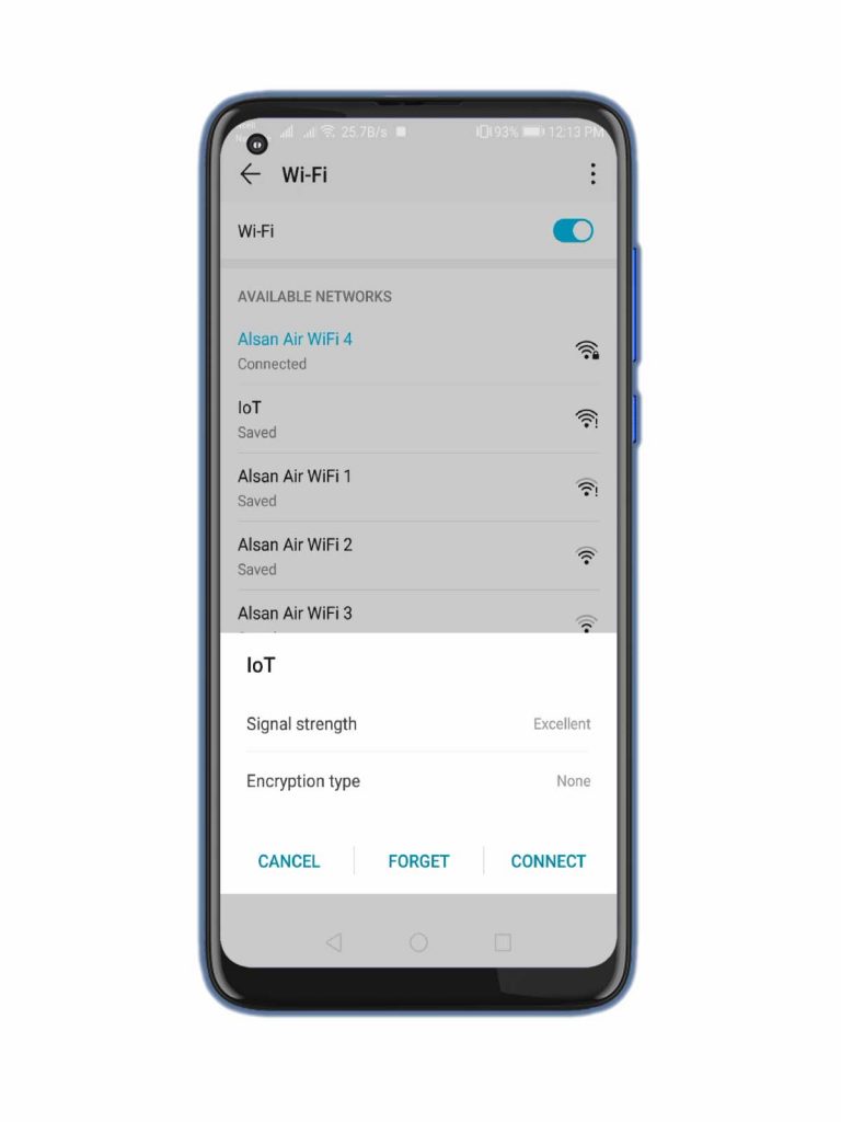
Firstly, connect to the WiFi Access Point that we have created with the name IoT a open network. because we haven’t added password in the password field in the code. But, Your may be different if you have changed it in the program.
Secondly, Go to the browser and type 192.168.4.1 IP address assigned to NodeMCU board.
Finally, You will see the field name SSID, password, and Authentication token. Just enter your credentials and then submit. You will see the message credentials received by the ESP Board.
As soon as credentials is received, It will be stored in EEPROM and AP mode is turned off. Hence, Your NodeMCU will be connected to your WiFi Network.
Now, Simply Open the Blynk app and You can see the device is online. Further, you can now turn on or off the users from anywhere in the world. usually, you can also monitor the device remotely, if there is an unauthorized person trying to access your door lock or not.
Also read: How can IoT help within the COVID-19 crisis
Video Tutorial on IoT based RFID smart door lock system using NodeMCU
This is the video that demonstrates how we made an IoT based RFID smart door lock system using NodeMCU ESP8266 Board.
Conclusion
Finally, we have successfully made an IoT based RFID smart door lock system using NodeMCU ESP8266, RFID MF-RC522, Servo Motor, a Buzzer, and Two LEDs. I hope you enjoyed reading this article. For more amazing content keep supporting us by sharing the post on social media.


how to install otablynk credentials library its showing an error
Error compiling for board nodemcu 1.0
Firstly Kudos to the Team, “Your smart lock system is a game-changer!”
HI! Why I have error compiling for board Node Mcu? Please help!
Use old version of library Blynk (1.0.0)