Overview
Hello and welcome to the Arduino Projects. In this article, I will teach you how to connect the joystick to the Arduino board. And we will use our knowledge from the previous article to connect four LEDs through the Arduino board as well. Then we will program the Arduino so that we can control the four LEDs using the joystick. Hence, today’s topic is all about the Arduino tutorial to control LEDs using Joystick.
What is Joystick?
The very first thing that comes to our mind while listening to the word “Joystick” is simply a game controller. Because everybody has seen it while playing video games. But, apart from gaming, it can wide range of applications in electronics. Actually, the joystick is the combination of two potentiometers for the X and Y Plane. It gives analog data to the Arduino by reading the voltage from the potentiometer. This analog value get changes as we move the joystick shaft.
Generally, it has five pinouts:
GND
5 Volt/VCC
VRX
VRY
SW

Components Required for this project
- Arduino UNO
- Joystick Module
- 4 LEDs
- 4 Resistor: 220-ohm
- Connecting wires
- Breadboard
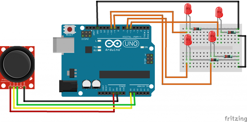
Circuit Diagram of this project
Interface LEDs to the Arduino
Firstly, let’s begin by attaching the Arduino GND pin to the corner of the breadboard using a jumper wire. Now we connect the second row of the breadboard to the last row of the breadboard as you can see in this circuit diagram. Using a second jumper wire. In this way, we have connected the second column of the breadboard to the GND pin of the Arduino Board.
Secondly, we will connect one leg of the 220-ohm resistor to the ground. Similarly, the other leg will be somewhere on the board(in a suitable place). Now we’ll take our LED and all you people know that LED has two legs. The shorter one is the cathode and the long leg is the anode. As always, the cathode is negative and the anode is positive. Hence, we will connect the cathode the short leg to the ground through the resistor. So, the resistors connect to the ground and then it’s connected to the cathode leg of the LED. Now we will repeat this process for the other three LEDs. Okay, now we’ve connected the four LEDs. The cathode Leg of each LED connected to the ground through the 220-ohm resistor.
Finally, we will start connecting the anode legs of each LED to the Arduino board. As shown in the circuit diagram.
- First LED Anode to the Pin 5 on the digital side of the Arduino.
- The second LED Anode to Pin 6 on the digital side of the Arduino.
- Third LED Anode to Pin 5 on the digital side of the Arduino.
- The fourth LED Anode to Pin 5 on the digital side of the Arduino.
Interface Joystick with the Arduino
Basically, Joystick has five pins Ground, 5Volt, VRX, VRY, and SW -we’re gonna just ignore that. So let’s connect these pins with the Arduino.
- GND pin to the GND pin of Arduino
- +5 volt pin to the 5volt pin of Arduino
- VRX pin to the A0 pin of Arduino
- VRY pin to the A1 pin of Arduino
Finally, we have finished the wiring and we’re ready to upload the code.
Program Source Code
Explanation
Let’s begin by defining or declaring variables that represent our LEDs. So we have LED one, two, three, and four and they’re connected to pin 5, 6, 9, and 10 respectively.
int led1 = 5;
int led2 = 6;
int led3 = 9;
int led4 = 10;
We also have to define the joystick in the VRX and VRY. VRX is connected to A0. And so we’re going to create the variable until a joystick_ x give it the value from A0 pin. Similarly, the other variable is joystick_y and going to give it the value to A1.
// define joystick pins
int joystick_x = A0;
int joystick_y = A1;
Next, we declared two variables joystick_ xvalue and joysticks_yvalue. These two variables will store the X and Y read incoming from the joystick respectively.
//read values from the analog pin
int joystick_xvalue = 0;
int joystick_yvalue = 0;
Then we have the setup section. In the setup section, we have to define the LEDs as a digital output. So we use the pinMode function. And when you set the LEDs as digital output pins, we use the same function to define the joystick_x as an input pin A0 and the joystick_y as an input pin A1.
void setup() {
  // put your setup code here, to run once:
  pinMode(led1, OUTPUT);
  pinMode(led2, OUTPUT);
  pinMode(led3, OUTPUT);
  pinMode(led4, OUTPUT);
  pinMode(joystick_x, INPUT);
  pinMode(joystick_y, INPUT);

}
Then you have the loop section. I start by assigning the values 0 to joystick_x value and joystick_y values. Every time we loop they’re gonna be assigned the value zero and then we’ll get to reading to see where the joystick is at?
void loop() {
  // put your main code here, to run repeatedly:

  joystick_xvalue = 0;
  joystick_yvalue = 0;

  //read values from joystick_x
  joystick_xvalue = analogRead(joystick_x);
  joystick_xvalue = map (joystick_xvalue, 0, 1023, -90, 90);

  //read values from joystick_y
  joystick_yvalue = analogRead(joystick_y);
  joystick_yvalue = map (joystick_yvalue, 0, 1023, -90, 90);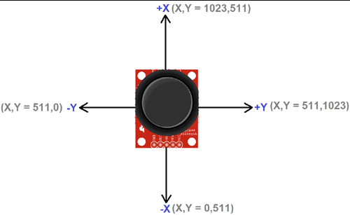
Finally, I have added some of the if statements to control LEDs using Joystick.
 if(joystick_xvalue < -5){
    digitalWrite(led1, HIGH);
    digitalWrite(led2, LOW);
    digitalWrite(led3, LOW);
    digitalWrite(led4, LOW);
  }
  else if(joystick_xvalue > 5){
    digitalWrite(led1, LOW);
    digitalWrite(led2, HIGH);
    digitalWrite(led3, LOW);
    digitalWrite(led4, LOW);
  }
  else if(joystick_yvalue < -5){
    digitalWrite(led1, LOW);
    digitalWrite(led2, LOW);
    digitalWrite(led3, HIGH);
    digitalWrite(led4, LOW);
  }
  else if(joystick_yvalue > 5){
    digitalWrite(led1, LOW);
    digitalWrite(led2, LOW);
    digitalWrite(led3, LOW);
    digitalWrite(led4, HIGH);
  }
  else{
    digitalWrite(led1, LOW);
    digitalWrite(led2, LOW);
    digitalWrite(led3, LOW);
    digitalWrite(led4, LOW);
  }
Full Source Code
int led1 = 5;
int led2 = 6;
int led3 = 9;
int led4 = 10;

// define joystick pins
int joystick_x = A0;
int joystick_y = A1;

//read values from the analog pin
int joystick_xvalue = 0;
int joystick_yvalue = 0;

void setup() {
  // put your setup code here, to run once:
  pinMode(led1, OUTPUT);
  pinMode(led2, OUTPUT);
  pinMode(led3, OUTPUT);
  pinMode(led4, OUTPUT);
  pinMode(joystick_x, INPUT);
  pinMode(joystick_y, INPUT);

}

void loop() {
  // put your main code here, to run repeatedly:

  joystick_xvalue = 0;
  joystick_yvalue = 0;

  //read values from joystick_x
  joystick_xvalue = analogRead(joystick_x);
  joystick_xvalue = map (joystick_xvalue, 0, 1023, -90, 90);

  //read values from joystick_y
  joystick_yvalue = analogRead(joystick_y);
  joystick_yvalue = map (joystick_yvalue, 0, 1023, -90, 90);

  if(joystick_xvalue < -5){
    digitalWrite(led1, HIGH);
    digitalWrite(led2, LOW);
    digitalWrite(led3, LOW);
    digitalWrite(led4, LOW);
  }
  else if(joystick_xvalue > 5){
    digitalWrite(led1, LOW);
    digitalWrite(led2, HIGH);
    digitalWrite(led3, LOW);
    digitalWrite(led4, LOW);
  }
  else if(joystick_yvalue < -5){
    digitalWrite(led1, LOW);
    digitalWrite(led2, LOW);
    digitalWrite(led3, HIGH);
    digitalWrite(led4, LOW);
  }
  else if(joystick_yvalue > 5){
    digitalWrite(led1, LOW);
    digitalWrite(led2, LOW);
    digitalWrite(led3, LOW);
    digitalWrite(led4, HIGH);
  }
  else{
    digitalWrite(led1, LOW);
    digitalWrite(led2, LOW);
    digitalWrite(led3, LOW);
    digitalWrite(led4, LOW);
  }

  delay(15);
}
Video Tutorials
Conclusion
Finally, we have completed the Arduino Tutorial to Control LEDs using Joystick. Now, you can control the four LEDs using the Joystick module Interfaced with Arduino Board. We hope you found this project useful! Drop a comment below if you have any doubts or queries. We’ll do our best to answer your questions.