In this article, we’re going to do a water level sensor Arduino tutorial. We’ll go through the entire process of wiring the sensor, and it’s working principle. We will provide you a Program Code examples to get you started with these projects. Actually, This sensor can be used as a water leak detection sensor as well.
- Hardware Overview
- Working Principle of Water Level Sensor
- Pinout of Water Level Sensor
- Components Required for this Project
- Interface the Water Level Sensor with Arduino
- Arduino water level sensor with LCD Display
- Program Code for (Serial Console)
- Calibration Method
- Arduino Water level Code (LCD Screen)
- Video Tutorial
- Uses of The Water Level Sensor
- Conclusion:
Hardware Overview
Basically, this water level sensor comes with only 3 pins. Namely, Ground, +5Volt, and Signal Pin. Hence it is very easy to interfere with the Arduino board. Here the signal pin is an analog output so we will connect it to any analog pin on the Arduino board. This analog water level sensor board has several copper traces on it. Five of them are power traces and five are sense traces. These copper traces are not connected but, they will be bridged by water when submerged in water.
Note: As we all know power water is non-conductive. But, Actually, the minerals and impurity present in the water make it conductive. This point is very important to understand because your sensor may be more or less sensitive based on the type of water you have used. Usually, you need to change the value in the code to get accurate readings. Ultimately, we’re just studying the resistance of the impurities in your water. Current can easily pass when more of the traces are bridged.
While reading the Water level sensor output with an analog input pin on Arduino. It will provide results between 0 and 500 only with the typical water that we get in public places.
Working Principle of Water Level Sensor
The working principle of the Water Level Sensor is very straightforward. Basically, the series of parallel conductors seen on the sensor acts as a variable resistor (Similar to the potentiometer). The resistance varies with the increase or decreases in the water level. Hence the change in the resistance is inversely proportional to the distance from the top of the sensor to the surface of the water.
- The resistance is inversely proportional to the height of the water.
- More the sensor immersed in water results in better conductivity and will result in lower resistance.
- Lesser the sensor immersed in water will result in higher resistance due to poor conductivity.
- Usually, this sensor provides output voltage according to the resistance, so by measuring it, we can determine the water level.
Pinout of Water Level Sensor
The Water Level sensor is super easy to connect because it has only three pinouts.
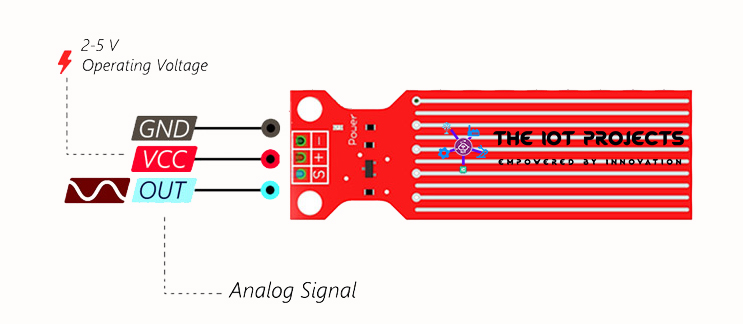
- S (Signal) pin is an analog output pin and will always be connected to the analog inputs pin in Arduino.
- + (VCC) pin is the power supply pin for the sensor. supplies power for the sensor. The recommended power of the water level sensor is between 3.3V – 5V. Note: analog output will vary depending on the voltage provided to the sensor.
- (GND) pin is for the ground connection.
Components Required for this Project
Here is a quick list of the components that are required to get started with this Arduino and Water level sensor project:
- Arduino Uno or Arduino Mega 2560
- Water Level Sensor (Leak Detection Sensor)
- Breadboard and Wires
- LCD Character Display (optional)
- 10K Potentiometer (optional)
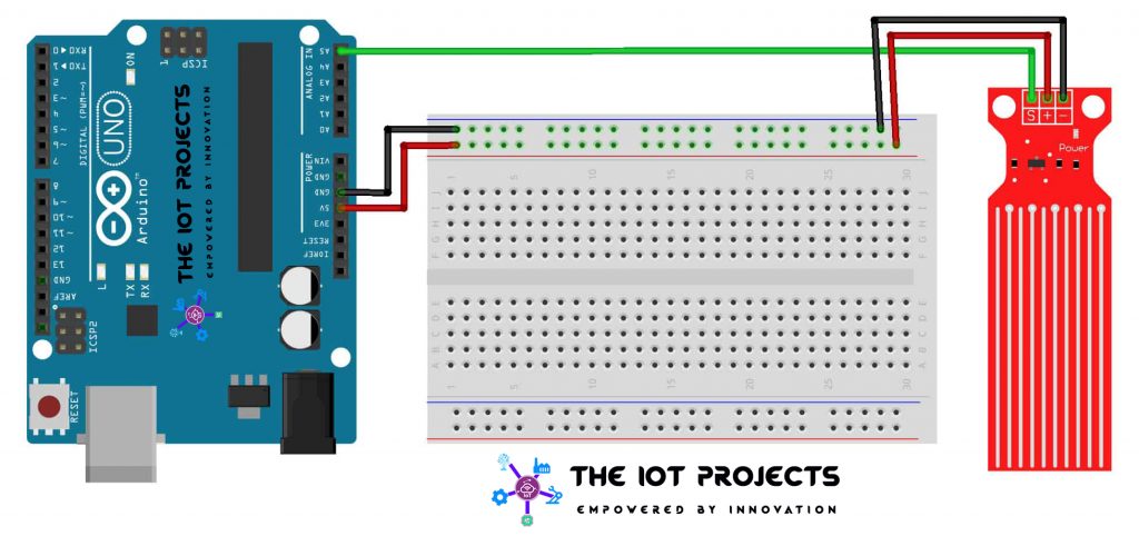
Interface the Water Level Sensor with Arduino
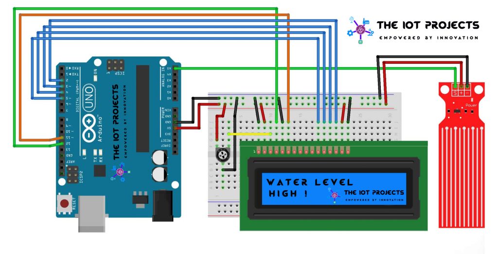
Interfacing the water level sensor is incredibly simple. We’ll use the following Circuit diagram to wire it up. And use it with the serial console, to get accurate readings out of your water level sensor. Hence, it is recommended to calibrate the sensor for the particular type of water that you plan to monitor.
Connections for Water Level Sensor and Arduino
- Signal pin to Arduino A5
- +5V pin to Arduino 5V
- (-)GND to Arduino GND
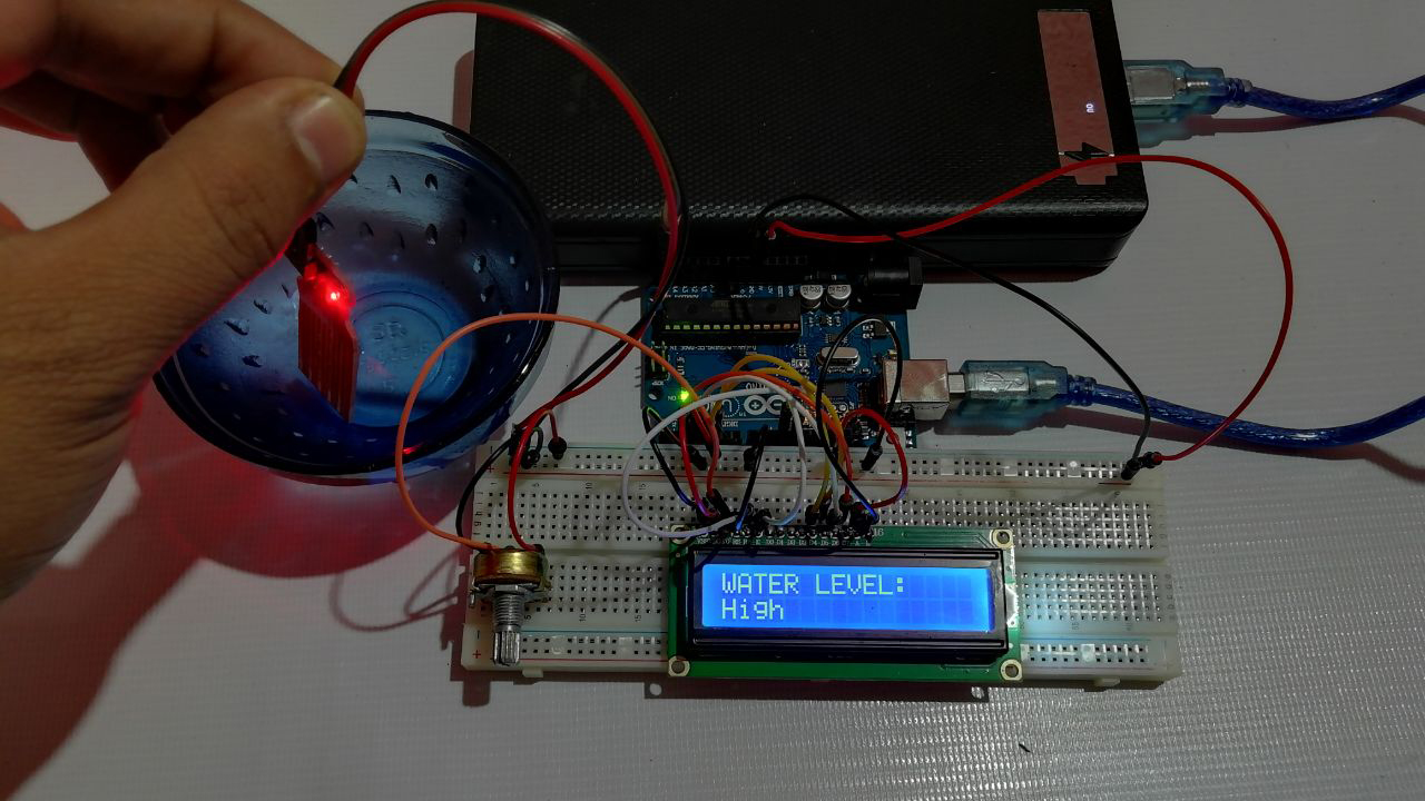
Arduino water level sensor with LCD Display
Finally, if you want to make it more advanced then add an LCD screen to display the output. Actually, you can follow the LCD connecting to Arduino Instructions to make it more advanced. So, here is the complete circuit diagram to Interface Arduino Water Level Sensor with an LCD.
Interface LCD to Arduino UNO
- VSS pin to ground
- VDD pin to 5V
- Vo to Center Pin of Potentiometer
- RS pin to digital pin 12
- R/W pin to ground
- Enable pin to digital pin 11
- D4 pin to digital pin 5
- D5 pin to digital pin 4
- D6 pin to digital pin 3
- D7 pin to digital pin 2
- Potentiometer Ends to +5V and ground
Program Code for (Serial Console)
This code is for those who don’t have LCD or Don’t want to display characters on this project. This code will print the output on the Serial Console. Basically, this is a great piece of code that helps you to learn to use a water level sensor with Arduino. Here are the things to note about this code.
You can delay time according to your needs. To check the data faster than around 100ms you have to turn off the serial output.
You may need to adjust the numbers. Because, it depends upon the impurities (minerals) present in your water. The sensor may be more or less sensitive to certain waters. Remember, pure water is non-conductive, its the minerals that make this work. The numbers I used to work well in my water. You can follow the calibration method to get perfect data to adjust this code numbers.
int resval = 0;  // holds the value
int respin = A5; // sensor pin used

void setup() {

  // start the serial console
  Serial.begin(9600);
}

void loop() {

  resval = analogRead(respin); //Read data from analog pin and store it to resval variable
 if (resval <= 100) {
    lcd.print("Empty ");
  } else if (resval > 100 && resval <= 155) {
    lcd.print("Low ");
  } else if (resval > 155 && resval <= 170) {
    lcd.print("Medium ");
  } else if (resval > 170) {
    lcd.print("High ");
  }
  delay(1000);
}
Calibration Method
To get accurate readings out of your water level sensor. It is recommended to calibrate the sensor for the particular type of water that you plan to monitor.
Actually, you can use the code provided below for calibration. Using the circuit diagram above, note the outputs from the serial Monitor when the sensor is completely dry -vs- partially submerged in the water -vs- completely submerged.
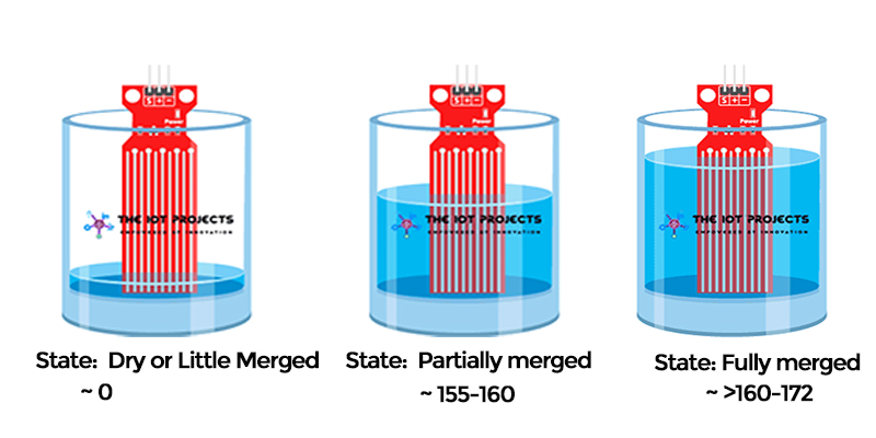
For example, using the same circuit above, and program code below. You will see the values like this in the serial monitor. For me, when the senor is dry (0) and when it is partially merged in the water (~420) and when it is completely merged (~520).
int resval = 0;  // holds the value
int respin = A5; // sensor pin used

void setup() {

  // start the serial console
  Serial.begin(9600);
}

void loop() {

  resval = analogRead(respin); //Read data from analog pin and store it to resval variable
Serial.println(resval);
  delay(1000);
}
Arduino Water level Code (LCD Screen)
This is the LCD version of the program code. Basically, it adds a loop to print to the LCD and move the cursor back on each cycle.
// include the library code:
#include <LiquidCrystal.h>
//initialise the library with the numbers of the interface pins
LiquidCrystal lcd(12, 11, 5, 4, 3, 2);

int resval = 0;  // holds the value
int respin = A5; // sensor pin used

void setup() {

  // set up the LCD's number of columns and rows:
  lcd.begin(16, 2);


}

void loop() {
  // Print a message to the LCD.
  lcd.print("WATER LEVEL: ");
  // set the cursor to column 0, line 1
  lcd.setCursor(0, 1);

  resval = analogRead(respin); //Read data from analog pin and store it to resval variable
  if (resval <= 100) {
    lcd.print("Empty ");
  } else if (resval > 100 && resval <= 155) {
    lcd.print("Low ");
  } else if (resval > 155 && resval <= 170) {
    lcd.print("Medium ");
  } else if (resval > 170) {
    lcd.print("High ");
  }
  delay(1000);
  lcd.clear();
}
Video Tutorial
Uses of The Water Level Sensor
Usually, we can use the water level sensor for many projects. It is actually more versatile than you think. So, here are some useful project ideas using this sensor.
- Can be used in water tanks to control water levels
- Water leakage detection
- Automatically turn ON/OFF pumps
- Can be used in factories, commercial complexes, apartments, home,
- Fuel tank level gauging
- Oil tank level control
- Rain Monitoring System
- and many more.
Conclusion:
Finally, we have completed the Water Level Sensor Arduino Tutorial. Now, your LCD screen (or serial console) should be showing the water level. We hope you found this project useful! Leave a comment below if you have any doubts or queries. We’ll do our best to answer your questions.


How can we measure deepest water body levels (like reservoirs, wells etc)?