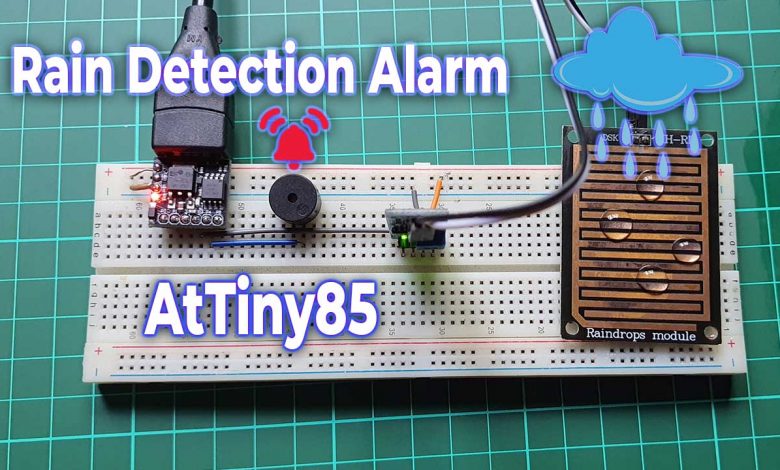
In this tutorial, we will make a rain detection alarm system using a rain sensor and AtTiny85 microcontroller. This small project has a wide range of applications. It can be used in weather stations, agriculture, farming, irrigation system projects, etc. You can also use this project in your home automation system to automatically close windows when rain is detected. We can also use this system on automobile wipers as we can find on expensive cars like tesla.
Overview: AtTiny85 based Rain Detection System
In this project, we will connect the rain sensor to the Digispark Attiny85. From the Analog pin of the rain sensor, we get some value which is then compared with a predefined value. If the Analog value is lesser than the predefined value it will turn on Buzzer. You can also add a relay and attach a motor to this project to automatically close windows.
For example, If you are away from home and you forget to close the window. Weather nowadays is unpredictable so it starts raining. The sensor detects raindrops and sends values to the microcontroller. Now it compares with a predefined value to check if it was raining. If a statement is true the relay is turned ON and closes windows automatically. Additionally, if there are fabrics outside, this system can be used to move them automatically inside the house. Depending on your knowledge you can use this project in your various applications.
Also Read:
Components Required
So let’s get started making a Rain Detection Alarm using AtTiny85 and a Rain sensor. To make this system more compact, I am using Digispark AtTiny85. Following are the lists of all the components that are required for building this project.
| S.N | Components Name | Quantity | |
|---|---|---|---|
| 1 | DigiSpark Attiny85 Board | 1 | https://amzn.to/3CNtfOZ |
| 2 | Rain Sensor | 1 | https://amzn.to/3VCa6Z7 |
| 3 | Buzzer | 1 | https://amzn.to/3eJ43kN |
| 4 | Jumper Wires | 5 | https://amzn.to/3MKjju6 |
| 5 | Breadboard | 1 | https://amzn.to/3eJiEMW |
Overview: Rain Sensor
The rain-detecting pad is primarily made up of copper traces. The variable resistor is made up of these traces. Hence the resistance varies when water drops are on the surface. As we know lower the resistance higher is the connectivity. Therefore, more water on the surface implies lower resistance. Similarly, Fewer water drops mean lower conductivity, which equals higher resistance. As a result, this resistance provides the voltage, which helps in the prediction of rain.
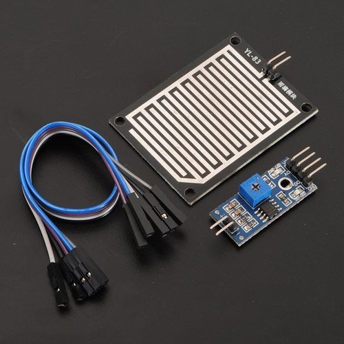
This module comes with LM393 High Precision Comparator. Which also converts the analog value into a digital value. The sensitivity of the digital value can be changed with the Potentiometer here.
In this module, you can see 6 PINs. These two Positive and Negative pins should be connected to the rain sensor pad. The other four pins are described below.
- VCC – This pin must be connected between 3.3v – 5v.
- GND – This should attach to the cathode terminal.
- AO – This pin can be used to read rainfall analog values.
- DO – This pin can be used to read digital values for rainfall.
AtTiny85 Pinouts
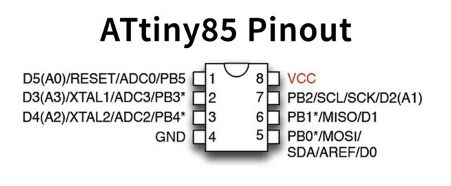
For a detailed description of pinout, dimension features, and specifications download the datasheet of ATTiny85
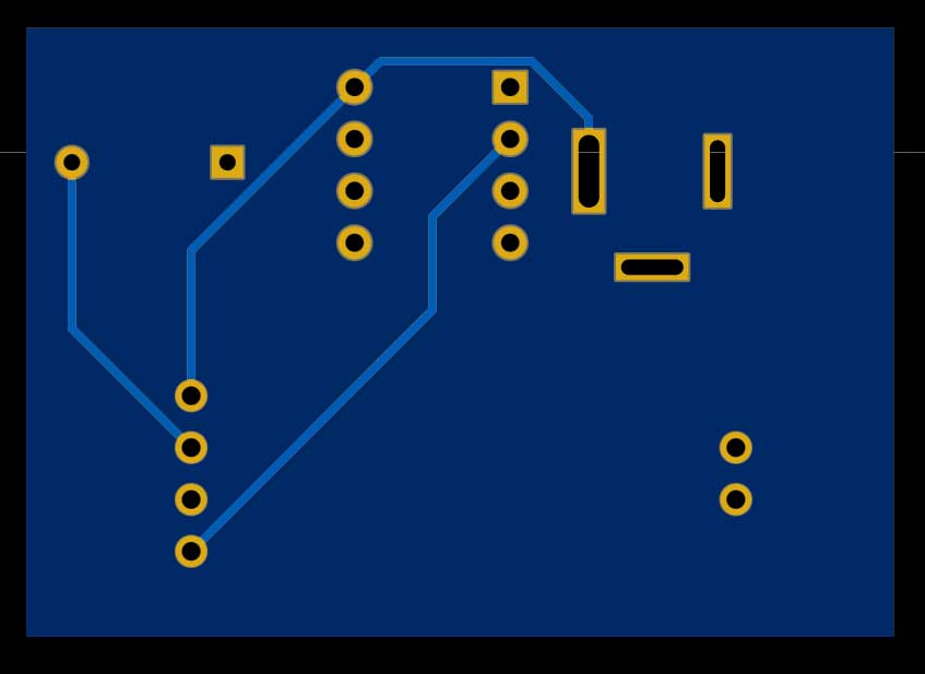
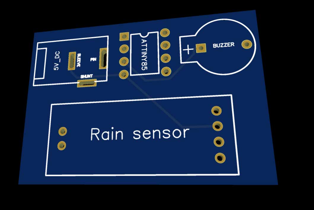
Rain Detection Alarm Circuit
Now. let’s interface Rain sensors, and Buzzer, with Digispark Attiny85.
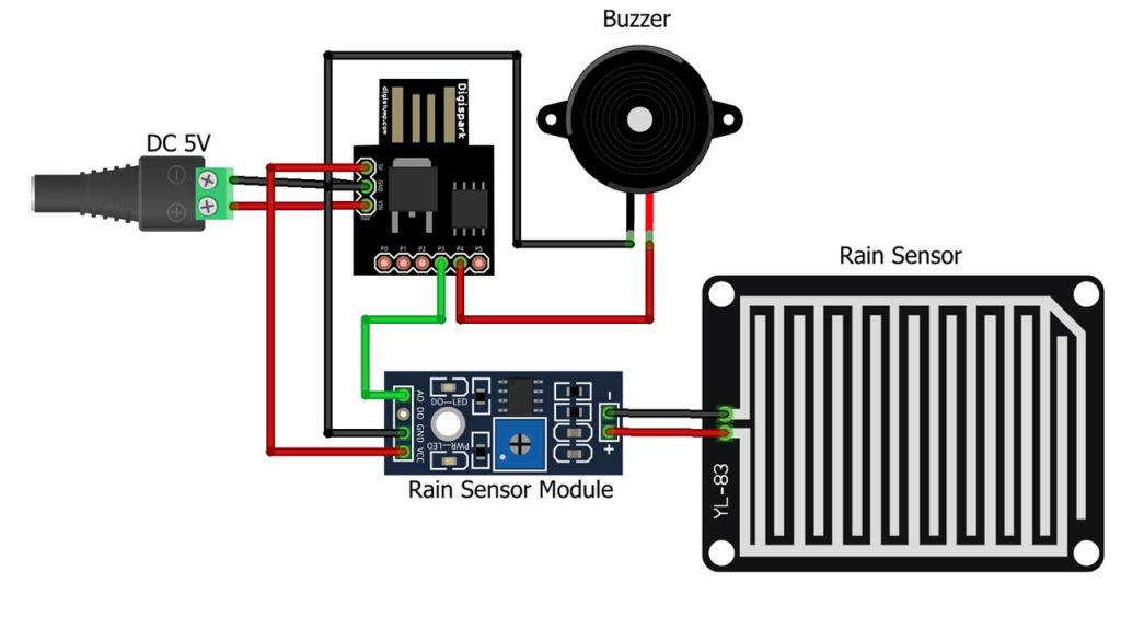
The circuit connection is fairly simple. Connect the Ground pin of the rain sensor, and buzzer to the GND pin of Attiny85. Now, connect the VCC pin of the Rain sensor to the 5 Volt pin. Similarly, A0 pin to P3 pin of Attiny85. Lastly, connect the buzzer positive pin to the P4 pin of Digispark Attiny85. You can follow the circuit diagram and table below to assemble the circuit.
| Rain Sensor | Attiny85 |
| VCC | 5V |
| GND | GND |
| A0 | P3 |
| Buzzer | Attiny85 |
| Positive | P4 |
| GND | GND |
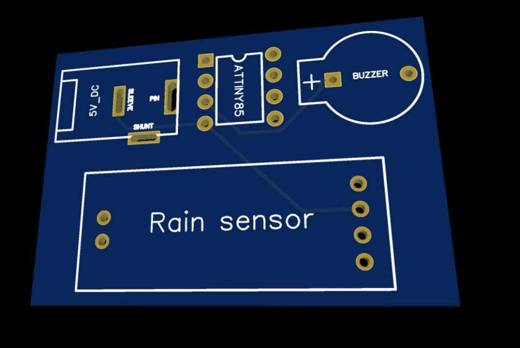
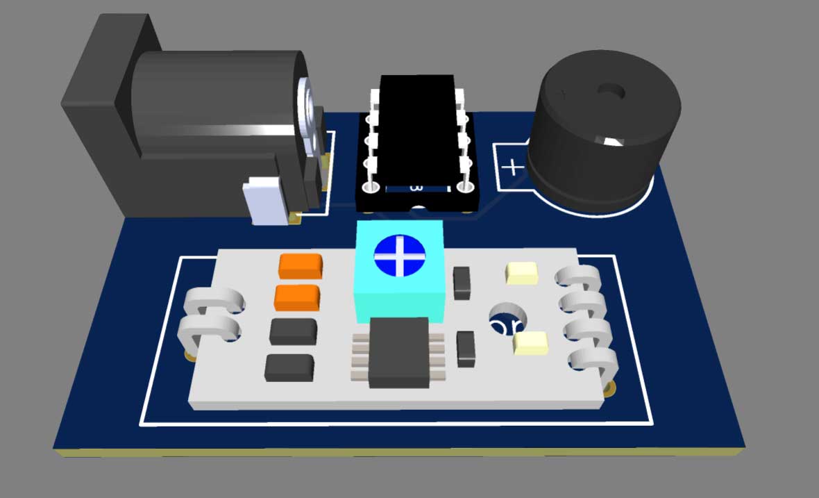
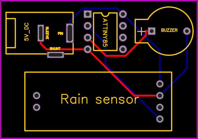
Ordering Custom PCB Online
Do you want professional PCBs like this one that looks so good? then use the services of PCBWay.com
Because PCBWay is a one-stop solution for all your PCB needs like PCB prototyping, SMD stencils, PCB assembly, 3D printing, etc. Currently, PCBWay 5th PCB Design Contest is going on. So, if you are interested you can apply from here. Recently, they have moved to a new factory and offer you up to 20% discount on 4-layer PCBs and 6-layer PCBs.

So, get your first prototype PCB ready from pcbway.com, the Gerber file link is provided below.
- Just click on the PCB Instant quote tab.
- Then click on Quick Order PCB.
- Now Upload your Gerber file
- Select your preferred shipping method
- Place your order.
Program code
Here I will explain each and every step of the program code. It will help you to understand and modify it according to your requirements. First, we defined the variable “Buzzer” for the buzzer, and “Sensor” for the Rain sensor, with their interfaced pin with Attiny85.
int Buzzer = 4; //Buzzer P4
int Sensor = 3;  // Rain sensor connected to P3
In a void setup, we have defined the pinMode function for Buzzer.
void setup() {
  pinMode(Buzzer, OUTPUT);
}
Here, in a loop, the program reads the analog data from the rain sensor. Then the value is checked by an IF condition and if it is less than 380, the Buzzer is turned ON. Else the code is designed to turn OFF the Buzzer.
void loop() {
  int value = analogRead(Sensor);//read value from P3 pin
  if (value < 380) {   //check condition
    digitalWrite(Buzzer, HIGH);
  } else {
    digitalWrite(Buzzer, LOW);
  }
}
Rain Detection Alarm Final Program code
This is the final program code for the Rain Detection Alarm using AtTiny85. Copy this code and paste it into your Arduino IDE.
// Rain Detector using Attiny85
// Using Digispark ATTINY85
int Buzzer = 4; //Buzzer P4
int Sensor = 3;  // Rain sensor connected to P3
void setup() {
  pinMode(Buzzer, OUTPUT);
}
void loop() {
  int value = analogRead(Sensor);//read value from P3 pin
  if (value < 380) {   //check condition
    digitalWrite(Buzzer, HIGH);
  } else {
    digitalWrite(Buzzer, LOW);
  }
}
Uploading code & testing project:
Before uploading the code, make sure you have set up your Arduino IDE for the Digispark Attiny85 board.
Now copy the program code provided for the Rain Detection Alarm System using AtTiny85 from above. Select “Digispark (Default-16.5Mhz)” Board from Tools Menu. Also, select the programmer as “Micronucleus” and choose its COM port.
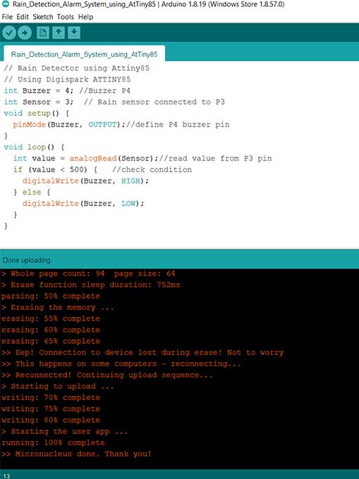
Finally, press the upload button after compiling the code, connect your Digispark Attiny85 board within 60 seconds. Wait for “Micronucleus done. Thank you!” Message for the successful upload of the program.
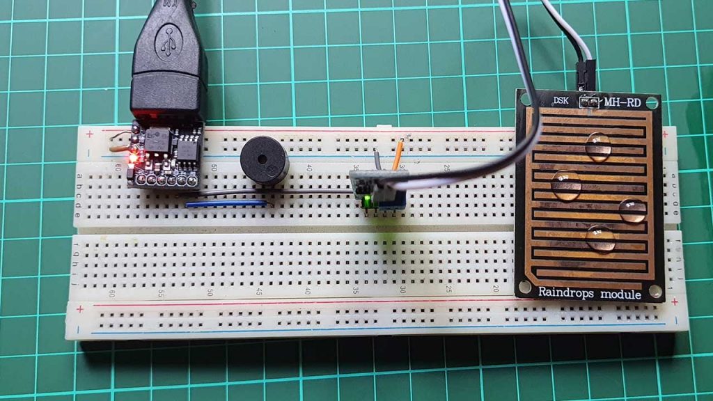
Now it’s time to test the Rain Detection Alarm System using the AtTiny85 project. Gently pour some water droplets on the rain sensor and you will start getting feedback from the buzzer.
Conclusion
So, that’s all for this Rain Detector Project using Attiny85. This is a very useful project and has a wide range of applications. If you like this tutorial, then share this project with your friends. Need help? Comment down below.