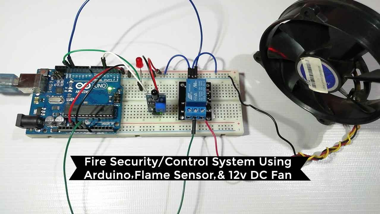
Today we will learn to make Fire Security System using Arduino & Flame Sensor. Actually this system will be an automated system. i.e. once we deploy the system it works automatically. So, let’s make a Fire security/control system using Arduino UNO, Flame sensor, and 12 volt DC Fan. So let’s get started without any delay.
Components required
Here are the components required for the Fire Security System using Arduino.
- Arduino UNO
- 12volt DC fan
- Relay Module
- Flame Sensor
- LED
- Breadboard
- Few jumper wires
Circuit diagram of fire control system
Now it’s time to interfere with all the components to the Arduino UNO board.
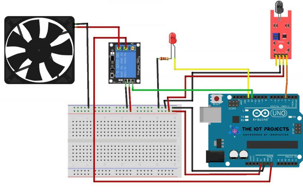
- First of all, connect the 5volt to the Positive rail on the breadboard.
- Then connect GND Pin to the negative rail of the breadboard.
- To interfere with the flame sensor Connect Vcc and GND to Vcc and GND on the breadboard.
- Now Connect the D0 pin(signal pin of the flame sensor) to pin 3 of Arduino.
- Similarly, interface single channel relay GND and Vcc pin to GND and Vcc. Then, Input Pin to Arduino Pins no 12.
- Now let’s connect the positive terminal of LED to pin 13 of Arduino and Negative Terminal to GND.
- Finally, connect 12v DC fan Vcc to the common of the relay. In normally open, connect the positive terminal of the fan. Here relay works as a switch.
- Finally, the Negative Terminal of DC fan to the GND pin on the breadboard.
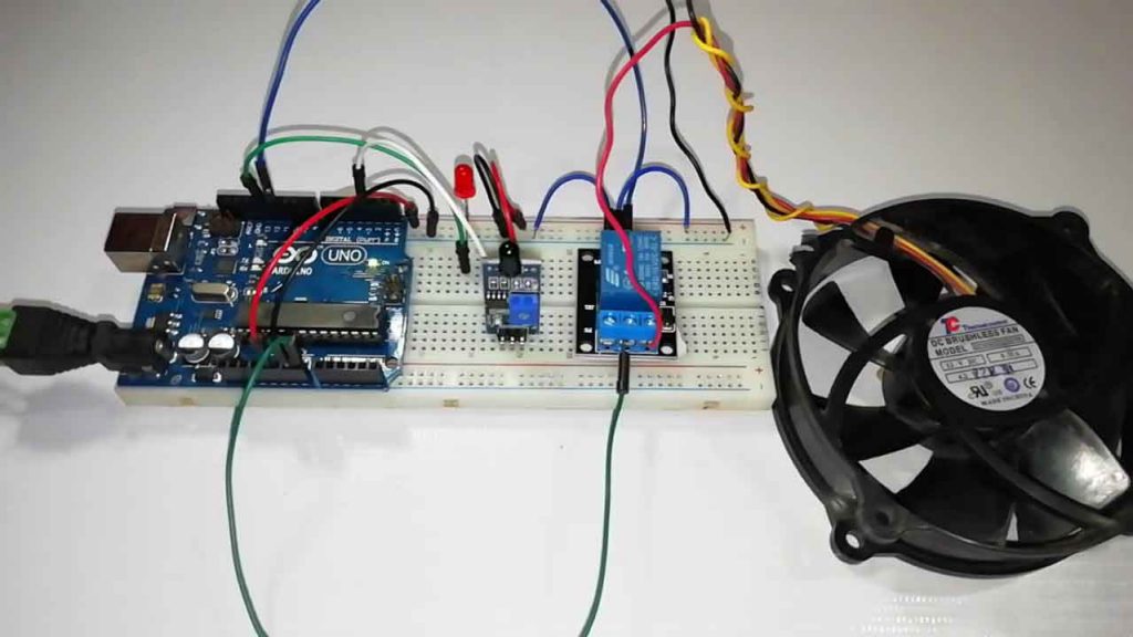
Actually, we have successfully assembled the circuit. Now let’s get into the programming part. The programming code is provided below.
Program Code Explanation
The program code for Fire Security System using Arduino & Flame Sensor is very easy and simple to understand. Anyone with a basic knowledge can code the program for this system. Here, LED, Relay, and flame sensor pins are defined according to our circuit diagram.
int LED = 13;
int RELAY = 12;
int Flame_sensor = 3;
The serial monitor begins at a baud rate of 9600 to debug the program.
void setup()
{
  Serial.begin(9600);
The pinMode function for LED and Relay is defined as output and for the flame sensor, it is defined as input.
pinMode(LED, OUTPUT);
  pinMode(RELAY, OUTPUT);
  digitalWrite(RELAY, HIGH);
  pinMode(Flame_sensor, INPUT);
In the void loop, If flame_detected==0 then it will execute some commands like Flame or Fire detected, and immediate action is taken. Here we can see the status on the serial monitor. Where LED is turned ON and the DC fan is also turned ON.
void loop()
{
  Flame_detected = digitalRead(Flame_sensor);
  Serial.println(Flame_detected);
  //delay(100);
  if (Flame_detected == 0)
  {
    Serial.println("Flame detected...! take action immediately.");
    digitalWrite(LED, HIGH);
    digitalWrite(RELAY, LOW);
    delay(500);
  }
If the above statement goes false It simply displays No flame detected and no action is taken.
else
  {
    Serial.println("No Flame detected. stay cool");
    digitalWrite(LED, LOW);
    digitalWrite(RELAY, HIGH);
  }
}
Isn’t the programming code is super easy to understand? However, if you still have any queries regarding this program code. You can ask me in the comment section below.
Fire Security System Arduino Program Code
This is the full program code for Fire Security System using Arduino & Flame Sensor project. just copy the below code and paste it in your Arduino IDE Program.
int LED = 13;
int RELAY = 12;
int Flame_sensor = 3;
int Flame_detected;
void setup()
{
  Serial.begin(9600);
  pinMode(LED, OUTPUT);
  pinMode(RELAY, OUTPUT);
  digitalWrite(RELAY, HIGH);
  pinMode(Flame_sensor, INPUT);
}
void loop()
{
  Flame_detected = digitalRead(Flame_sensor);
  Serial.println(Flame_detected);
  //delay(100);
  if (Flame_detected == 0)
  {
    Serial.println("Flame detected...! take action immediately.");
    digitalWrite(LED, HIGH);
    digitalWrite(RELAY, LOW);
    delay(500);
  }
  else
  {
    Serial.println("No Flame detected. stay cool");
    digitalWrite(LED, LOW);
    digitalWrite(RELAY, HIGH);
  }
}
Uploading Code
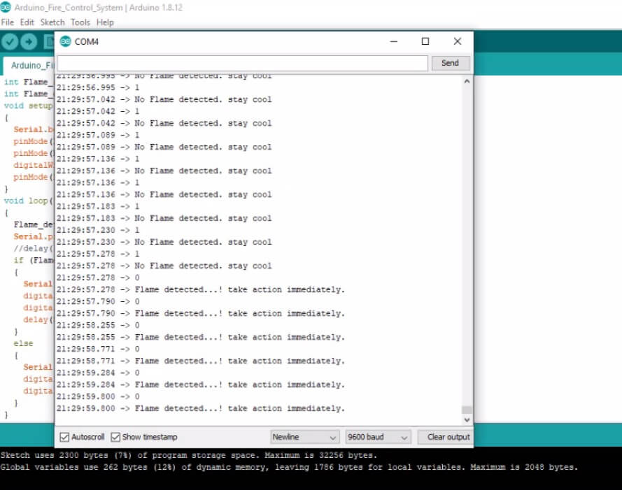
Now go to the Tools menu and select the Arduino UNO board and its COM Port. Now, click on upload to upload the code to the Arduino board.
After successful upload, open your serial monitor at the baud rate of 9600 to see the status.
Here we need some more speed on the fan, so connect the 12v adapter and change the common Pin connected to Vcc to Vin pin of Arduino.
Now it works perfectly. Let’s see some demonstrations.
Video Demonstration of Arduino Fire Security system
Wrapping up
So that’s all for today. We have successfully made an Arduino based fire control system. I hope this tutorial was helpful to you.
Recommended Projects:
- IoT based Silent Intruder Alarm using Arduino
- Dual Axis Solar Tracker Arduino Project Using LDR & Servo Motors
- Electronic Voting Machine Using Arduino & LCD Display
- Temperature Controlled Home Automation using Arduino
- Water Level Sensor Arduino Tutorial
- Interface LDR Photo Resistor to Arduino and Control LEDs
- DIY Mobile Phone using GSM Module & Arduino with Nextion Display
- IoT Based RFID Attendance System using ESP32
- Home Automation with MIT App Inventor and ESP8266
- Arduino Tutorial to Control LEDs using Joystick
- How 555 IC works in Astable Operation & Monostable Operation
- Top 10 Coolest IoT Devices of 2020
- Password Security Lock System Using Arduino & Keypad


thanks a lot brother, but i want to add alarm with fan , csn it possible ?
Can We Use Mq 2 sensor And 12 v dc motor