IoT based Fire Detector & Automatic Extinguisher using NodeMCU
IoT Fire Detector Using NodeMCU ESP8266 & Blynk
- Overview: IoT Fire Detector & Extinguisher
- Requirements for IoT Fire Detector and extinguisher system
- Circuit Diagram
- PCBWay 4th PCB Design Contest
- IoT based Fire Detector App designed on Blynk
- Program Code Explanation
- IoT Fire Detector & Automatic Extinguisher using NodeMCU Program Code
- Uploading Code
- Video Demonstration of IoT based Fire Detector & Automatic Extinguisher using NodeMCU
- Wrapping up
Overview: IoT Fire Detector & Extinguisher
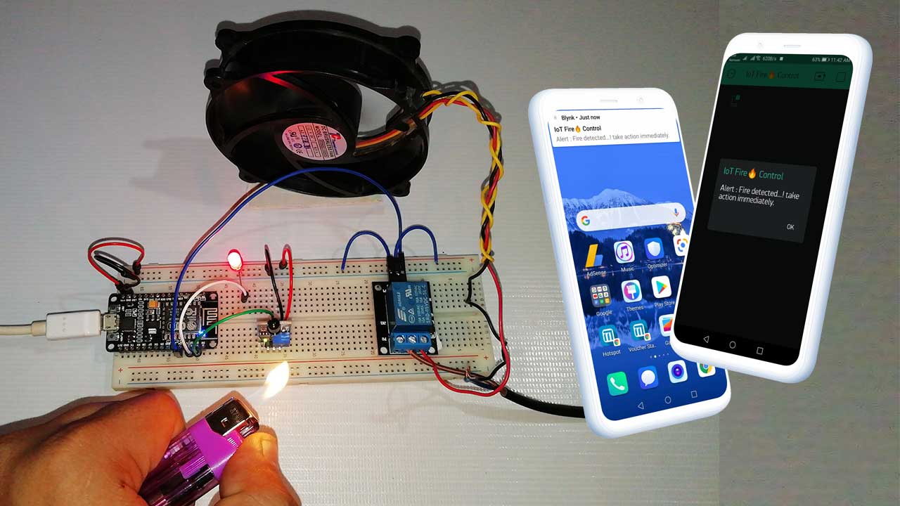
Nowadays, Fire detecting and Alerting system are very common in banks, offices, homes, etc. They usually detect fire and alert people with a siren. But, what happens, when nobody is there to listen to the Alarm? Like when nobody is at home or office. So, to inform the authority about fire incidents and automatically extinguish the fire. We have made this IoT Fire Detector & Automatic Extinguisher using the NodeMCU project. This project can be further modified to notify the fire control department automatically.
This IoT-based project detects the nearby flame using an Infrared Flame Sensor and then NodeMCU Tiggers the relay to extinguish the fire automatically. It also informs the authority using IoT Blynk Application. With the help of this project, you can easily understand the concept of a fire detector and alert system.
Requirements for IoT Fire Detector and extinguisher system
The following are the components required for making IoT based fire detector and automatic extinguisher system using NodeMCU:
| S.N | Components Name | Quantity | |
|---|---|---|---|
| 1 | NodeMCU ESP8266 12-E Development Board | 1 | https://amzn.to/3kiLhQ3 |
| 2 | A 5V Relay Module | 1 | https://amzn.to/388Wn4g |
| 3 | Infrared Flame Sensor | 1 | https://amzn.to/3kjJeuT |
| 4 | A LED | 1 | https://amzn.to/3mtrnEI |
| 5 | 12 volt DC Fan | https://amzn.to/3sGjlJz | |
| 6 | Few jumpers wires | 15 | https://amzn.to/3klh0A4 |
| 7 | 12-volt adaptor | 1 | https://amzn.to/3zr4ky1 |
| 8 | Breadboard | 1 | https://amzn.to/3mt0O2c |
Circuit Diagram
Now let’s start assembling all the components for the IoT-based Fire detector and automatic extinguisher system using NodeMCU(ESP8266) and flame sensor.
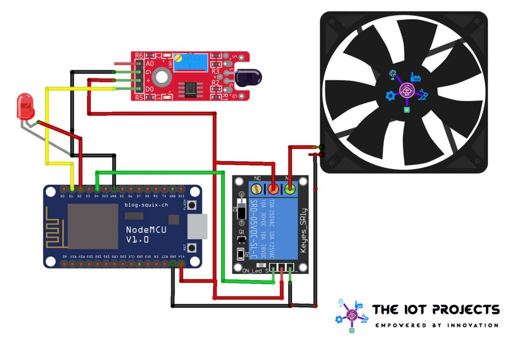
- First of all, connect the Vin pin to the positive rail on the breadboard.
- Then connect GND Pin to the negative rail of the breadboard.
- To interfere with the flame sensor Connect Vcc and GND to Vcc and GND on the breadboard.
- Now Connect the D0 pin(signal pin of the flame sensor) to the D1 pin of NodeMCU (ESP8266).
- Now let’s connect the Negative terminal of LED to the GND Pin of NodeMCU and the Positive Terminal to the D2 pin.
- Similarly, interface single channel relay GND and Vcc pin to GND and Vcc. Then, Input the Pin to NodeMCU D4 Pin.
- Now, connect the 12v DC fan positive terminal to the normally open (NO) Pin, and connect the positive terminal 12V adaptor to the common pin of the relay.
- Finally, the Negative Terminal of the DC fan to the 12v adaptor Negative Terminal.
Note: Here, the relay module works as a switch. we have successfully assembled the circuit. Now design the PCB and take part in PCBWay 4th PCB Design contest to win exiting prize of $6000.
PCBWay 4th PCB Design Contest
The PCBWay introduced their 4th PCB Design contest on their website.

- In this contest, there are two main themes and one free theme.
- In an IoT theme, you can make Home automation, wearable projects, embedded electronics, Internet connectivity, or other forms of hardware that communicate and interact with others using the Internet.
- You can make Robots, smart cars, drones, or other automated projects with a robot theme in this contest.
- If your project is not related to IoT or Robotics themes, then you can choose the free theme to submit your project.
You can submit your project between 9th, Aug 2021 to 30th, Nov 2021. Your project will be reviewed and the result will be announced on 13th DEC 2021. Your project must be plagiarism free otherwise you will be disqualified.
- These are the prizes that are waiting for you. So do not delay to submit your cool project within the described timeframe.

- Not only that, If you take part in this contest. You will get ESP32 Development board as a participation reward.

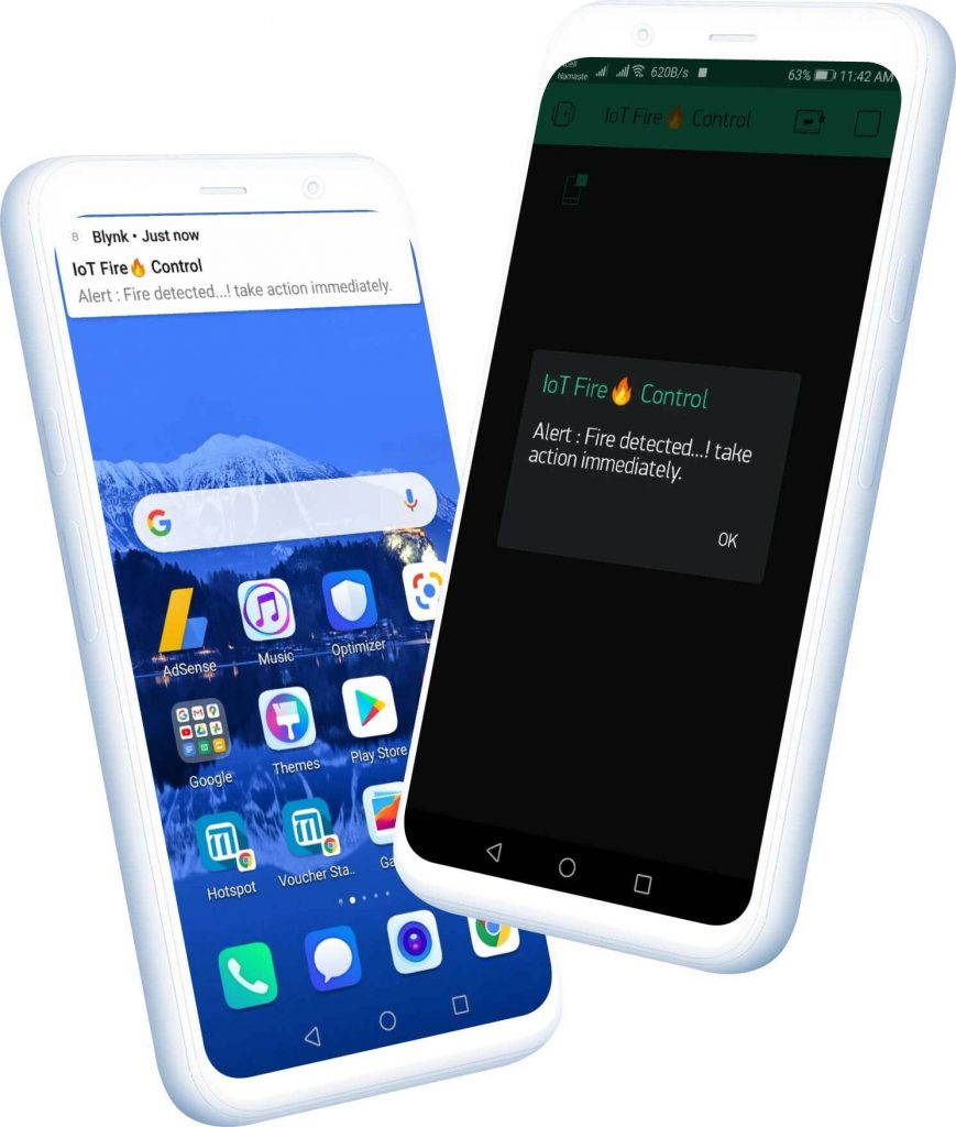
IoT based Fire Detector App designed on Blynk
I have done many projects related to IoT with the Blynk application and designed many apps before. In this session, I am designing IoT based Fire Alert Notifier and an automatic extinguisher App. So, Make sure you download and install the Blynk app from Playstore/Appstore.
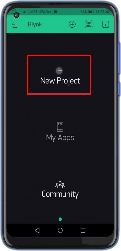
- First of all, open the blynk application.
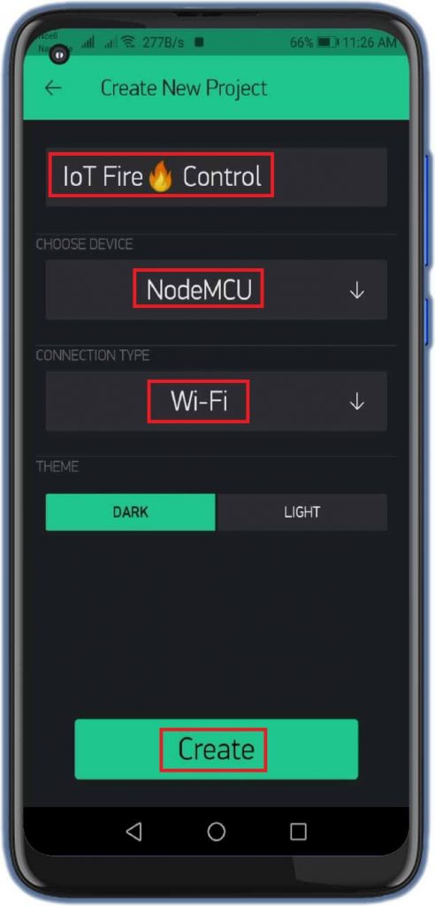
- Click on the create a new project and enter the project name as “IoT Fire Control“. Instead, you can type any name. You can change the name later.
- Click on Choice Tools and select NodeMCU ESP8266.
- Make sure the connection type is set to WIFI.
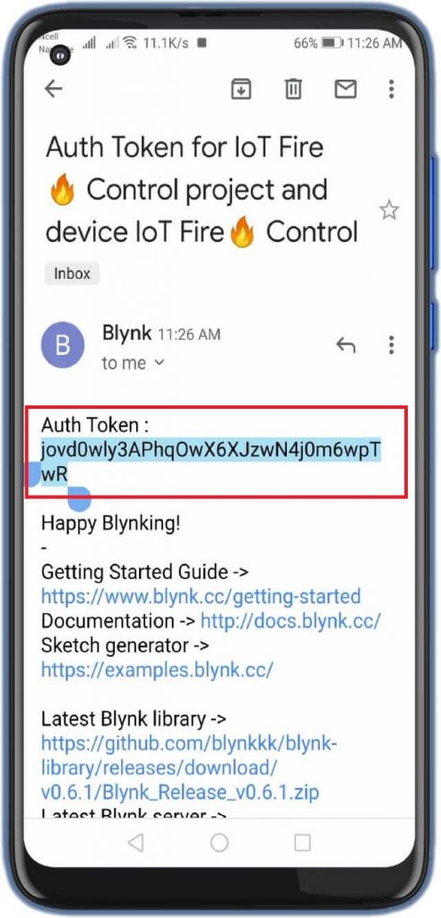
- Finally, click on the create button, and a verification token will be sent to your email ID, which will be used in the Program CODE.
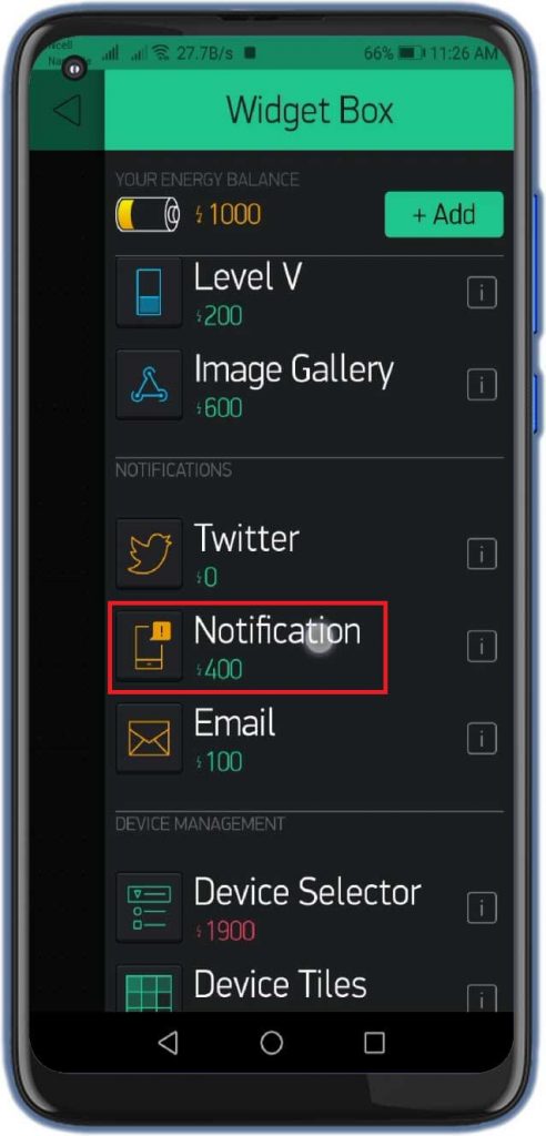
- Click anywhere on the screen, and search for the Notification Widget. Now Your designed IoT Fire Control application is ready to use.

Program Code Explanation
The program code for IoT Fire Detector & Automatic Extinguisher using NodeMCU is very easy and simple to understand. Anyone with a piece of basic knowledge can code the program for this system.
First of all, I started adding the libraries required for a Fire Detector & Automatic Extinguisher using ESP8266. The download link is provided below.
#define BLYNK_PRINT Serial
#include <ESP8266WiFi.h>
#include <BlynkSimpleEsp8266.h>
Here, integer variable LED, Relay, and flame sensor pins are defined according to our circuit diagram. The flame_detected integer variable is defined to read the value from the flame sensor.
int LED = D2;
int RELAY = D4;
int Flame_sensor = D1;
int Flame_detected;
Replace the following Blynk authentication token, WiFi SSID, and Password credentials with yours. This is the authentication token which was sent via email while building the Blynk IoT App. This authentication token will be mailed to your registered email ID.
char auth[] = "jovd0wly3APhqOwX6XJzwN4j0m6wpTwR"; //Auth code sent via Email
char ssid[] = "Alsan";
char pass[] = "12345678"
Custom function notifyOnFire() is created to read data, execute commands to trigger relay and notify the user through the Blynk IoT platform.
void notifyOnFire()Here Flame_Detected read the data from the flame sensor and Prints its value in the serial monitor. If its value is =0 then, Information is printed on the serial monitor as “Flame detected…! take action immediately”. At the same time, it triggers a notification on Blynk App, a Red LED is turned on as an indication, and Relay is turned ON to run a fan at a very high speed to extinguish the fire.
Flame_detected = digitalRead(Flame_sensor);
Serial.println(Flame_detected);
//delay(100);
if (Flame_detected == 0) {
Serial.println("Flame detected...! take action immediately.");
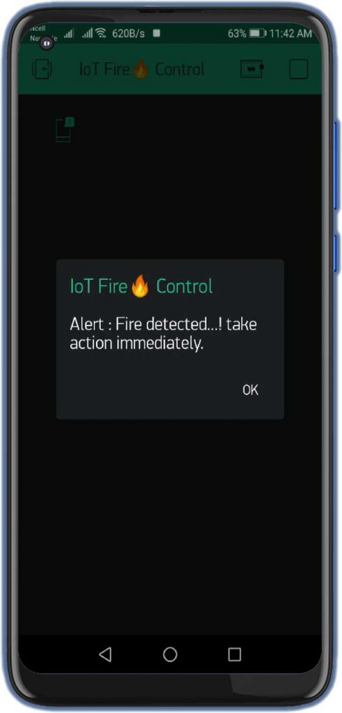
Blynk.notify("Alert : Fire detected...! take action immediately.");
digitalWrite(LED, HIGH);
digitalWrite(RELAY, LOW);
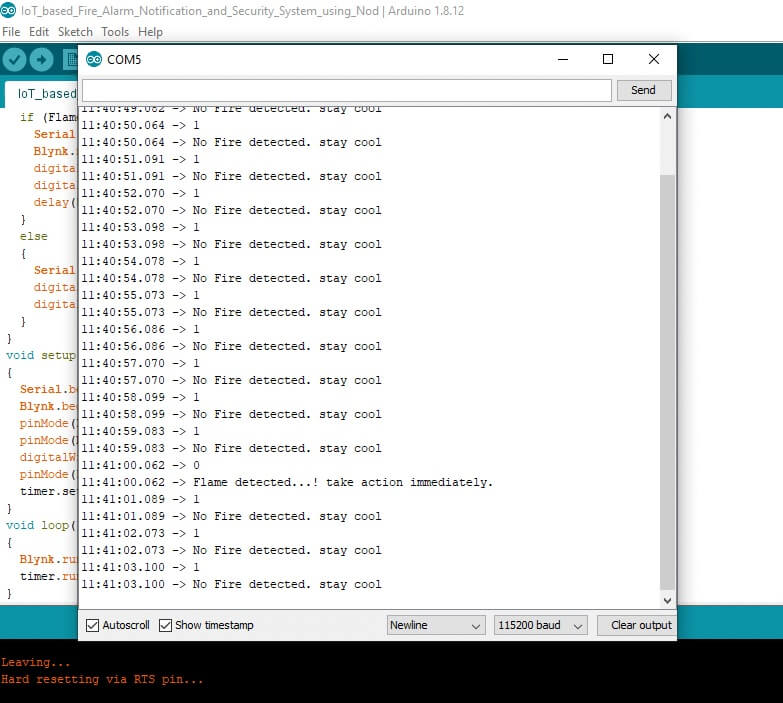
delay(500);In Else Condition it simply Prints “No Fire detected. stay cool” on the serial monitor and Relay and LED remains in the OFF state.
else
  {
    Serial.println("No Fire detected. stay cool");
    digitalWrite(LED, LOW);
    digitalWrite(RELAY, HIGH);
  }
Basically, on the setup part, Serial Monitor is initiated at the baud rate of 115200 with serial.begin function. Blynk WiFi authentication is initiated with Blynk.begin, and pinMode function is initialized as OUTPUT for LED and Relay. Similarly, for a flame sensor, the Input_Pullup argument is used. and finally timer interval for function notifyOnFire is defined as 1000L
void setup()
{
  Serial.begin(115200);
  Blynk.begin(auth, ssid, pass);
  pinMode(LED, OUTPUT);
  pinMode(RELAY, OUTPUT);
  digitalWrite(RELAY, HIGH);
  pinMode(Flame_sensor, INPUT_PULLUP);
  timer.setInterval(1000L, notifyOnFire);
}
On a Loop, part two function Blynk.run() and timer.run are executed.
void loop()
{
  Blynk.run();
  timer.run();
}
Isn’t the programming code is super easy to understand? However, if you still have any queries regarding this program code. You can ask me in the comment section below.
IoT Fire Detector & Automatic Extinguisher using NodeMCU Program Code
This is the full program code for IoT Fire Detector & Automatic Extinguisher using the NodeMCU project. just copy the below code and paste it in your Arduino IDE Program.
//Welcome to The IoT Projects
//IoT Based Fire Alarm Notification and control system using ESP8266
#define BLYNK_PRINT Serial
#include <ESP8266WiFi.h>
#include <BlynkSimpleEsp8266.h>


int LED = D2;
int RELAY = D4;
int Flame_sensor = D1;
int Flame_detected;

BlynkTimer timer;
char auth[] = "jovd0wly3APhqOwX6XJzwN4j0m6wpTwR"; //Auth code sent via Email
char ssid[] = "Alsan";
char pass[] = "12345678";

void notifyOnFire()
{
  Flame_detected = digitalRead(Flame_sensor);
  Serial.println(Flame_detected);
  //delay(100);
  if (Flame_detected == 0) {
    Serial.println("Flame detected...! take action immediately.");
    Blynk.notify("Alert : Fire detected...! take action immediately.");
    digitalWrite(LED, HIGH);
    digitalWrite(RELAY, LOW);
    delay(500);
  }
  else
  {
    Serial.println("No Fire detected. stay cool");
    digitalWrite(LED, LOW);
    digitalWrite(RELAY, HIGH);
  }
}
void setup()
{
  Serial.begin(115200);
  Blynk.begin(auth, ssid, pass);
  pinMode(LED, OUTPUT);
  pinMode(RELAY, OUTPUT);
  digitalWrite(RELAY, HIGH);
  pinMode(Flame_sensor, INPUT_PULLUP);
  timer.setInterval(1000L, notifyOnFire);
}
void loop()
{
  Blynk.run();
  timer.run();
}
Uploading Code
Now go to the Tools menu and select the NodeMCU ESP8266 12-E Development board and its COM Port. Now, click on upload to upload the code to the NodeMCU.
After successful upload, open your serial monitor at the baud rate of 115200 to see the status.
Video Demonstration of IoT based Fire Detector & Automatic Extinguisher using NodeMCU
Watch the video below which demonstrate IoT-based Fire Detector & Automatic Extinguisher using NodeMCU. If you like this video please subscribe to this channel. Your one subscription can make our day.
Wrapping up
So that’s all for today. We have successfully made an IoT based Fire Detector & Automatic Extinguisher using NodeMCU. I hope this tutorial was helpful to you.
Recommended projects
- Fire Security System using Arduino & Flame Sensor
- Contactless Smart Doorbell Using ESP8266 & Blynk
- Secure HTTPS Requests to URL Using NodeMCU ESP8266
- IoT based Silent Intruder Alarm using Arduino
- RFID Based Attendance System Using NodeMCU
- Connect RFID to PHP & MySQL Database with NodeMcu ESP8266
- IoT Based RFID Attendance System using ESP32
- IoT Based LED Control using Google Firebase & ESP8266
- BME280 Based Mini Weather Station using ESP8266/ESP32
- Home Automation with MIT App Inventor and ESP8266
- IoT Based Flood Monitoring System Using NodeMCU
- Internet Clock Using NodeMCU and without RTC Module
- IoT Based Patient Health Monitoring System Using ESP8266/ESP32
- Web Controlled Smart Notice Board using NodeMCU
- IoT vs IIoT and its protocols
- Top 10 Coolest IoT Devices of 2020


why you are used 1000L for timer!?? timer.setInterval(1000L, notifyOnFire)
Plz .. give a block diagram for this circuit diagram of fire detector and automatic extinguisher using nodeMcu
i u get the report of this project send me below