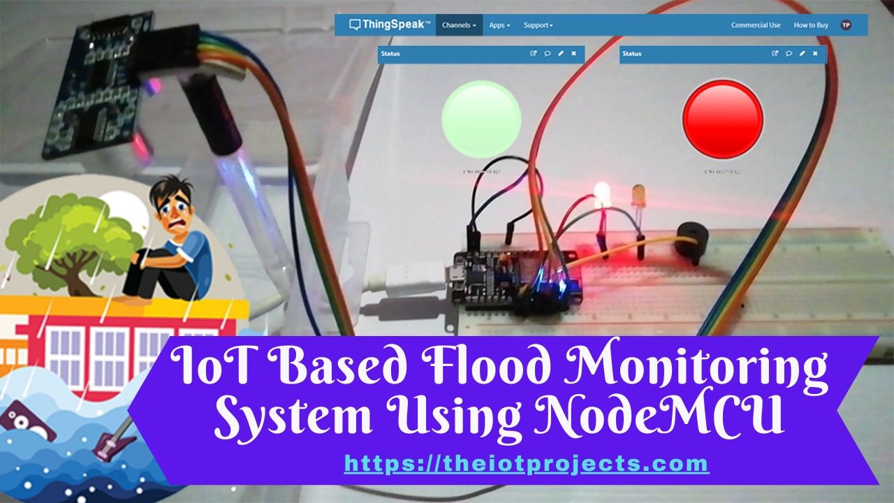
Today in this project we are going to make IoT Based Flood Monitoring System Using NodeMCU, Ultrasonic HC-SR04 Sensor & Thingspeak IoT Platform. As we all know that Flood is one of the major well Known Natural disasters. It causes a huge amount of loss to our environment and living beings as well. So in these cases, it is very important to get emergency alerts of the water level situation in different conditions in the river bed.
The purpose of this project is to sense the water level in river beds and check if they are in normal condition. If they reach beyond the limit, then it alerts people through LED signals with buzzer sound as well as internet applications. Here we are using the Ultrasonic HC-SR04 sensor to sense the river level and NodeMCU ESP8266 Microcontroller for data processing. The processed data will be uploaded to the ThingSpeak IoT Cloud Platform. Using which river levels can be monitored graphically from anywhere in the world.
- Required Components of Flood Monitoring System
- How this Flood Monitoring System Works?
- Ultrasonic HC-SR04 Sensor
- Schematic of IoT Based Flood Monitoring System
- Flood Monitoring System Using NodeMCU -Video Demonstration
- Set up a ThingSpeak account for Flood Monitoring & Alerting System
- Setting up Arduino IDE for NodeMCU Board
- Program Code explanation
- Program Sketch/Code
- Wrapping up
Required Components of Flood Monitoring System
These are the components required to make IoT Based Flood Monitoring System Using NodeMCU & ThingSpeak.
- NodeMCU ESP8266 Development Board
- Ultrasonic HC-SR04 Sensor
- Red and Green LEDs
- Buzzer
- Jumper wire
- Breadboard
- Power Supply
How this Flood Monitoring System Works?
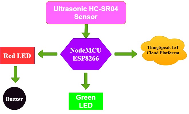
We have used ESP8266 NodeMCU to build many IoT projects before. The block diagram above shows the working of this IoT based flood monitoring system using the NodeMCU and IoT Platform. Here, the Ultrasonic sensor is used to detect river water levels. The raw data from the ultrasonic sensor is fed to the NodeMCU, where it is processed and sent to ThingSpeack for graphical monitoring and critical alerts. Here, the red LED and Buzzer is used to send an alert in a flooded condition. While Green LED is used for indicating Normal condition. are used to be alert in severe flood conditions, and green LEDs are used to indicate normal conditions.
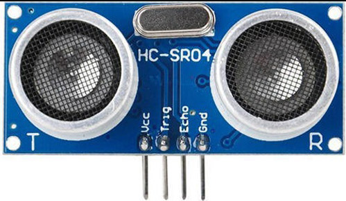
Ultrasonic HC-SR04 Sensor
Ultrasonic sensors work on the principle of ultrasound waves which are used to determine the distance for an object. An Ultrasonic sensor generates high-frequency sound waves. When this ultrasound hits the object, it reflects as the echo that the receiver sense. We can calculate the distance to the target object using the time required to reach the receiver for Echo.
Formula to calculate:
Distance= (Time x Speed of Sound in Air (340 m/s))/2
Ultrasonic distance sensors are of two ultrasonic transducers. One of them acts as a transmitter that converts the electrical pulse of the microcontroller into an ultrasonic sound pulse and is received by the receiver for transmitted pulses. If it receives them, then it produces an output pulse whose time period is used to determine the distance from the object.
Features:
Working voltage: 5V
Current working: 15mA
Working frequency: 40HZ
Measurement distance: 2cm - 4m
Measuring Angle: 15 Degree.
Trigging input pulse: 10uS
Learn more about ultrasonic sensors through its previous projects such as Read Ultrasonic Sensor data through webserver on a realtime chart.
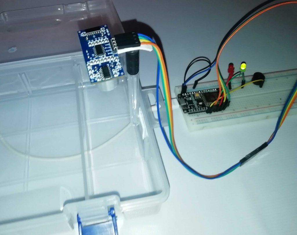
Schematic of IoT Based Flood Monitoring System
Interfacing NodeMCU ESP8266, Ultrasonic HC-SR04 Sensor, Buzzer, and LEDs (Red and Green) as shown in the following circuit diagram:
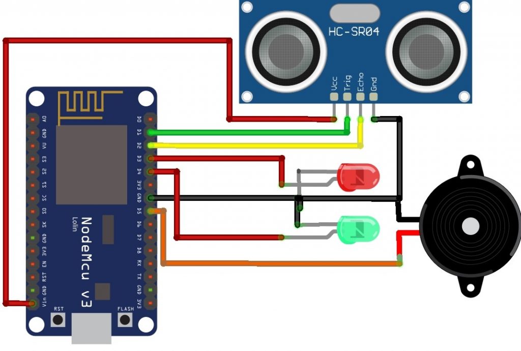
Interfacing HC-SR04 Sensor to NodeMCU
| Ultrasonic HC-SR04 | ESP8266 |
| Vcc Pin | Vin Pin |
| Trig Pin | D1 (GPIO 5) |
| Echo Pin | D2 (GPIO 4) |
| GND Pin | GND |
Connect Green and Red LEDs Negative Terminal to GND and Positive terminal to the D4 and D3 pin respectively. lastly, connect Buzzer GND to GND and Positive terminal to D5 pin of NodeMCU.
Flood Monitoring System Using NodeMCU -Video Demonstration
Set up a ThingSpeak account for Flood Monitoring & Alerting System
After the successful interface of the hardware parts according to the circuit diagram above. Now its time to set up the IoT platform, where data can be stored for online monitoring. Here we are using ThingSpeak to store data. ThingSpeak is a very popular IoT cloud platform that is used to store, monitor, and process data online.
Step 1: Sign up for ThingSpeak
First go to ThingSpeak and create a new free MathWorks account if you don’t already have a MathWorks account.
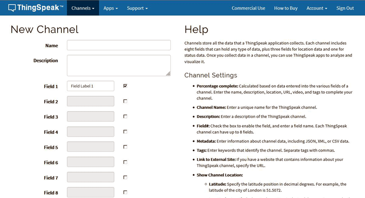
Step 2: Sign in to ThingSpeak
Sign in to ThingSpeak using your credentials and create “New Channel“. Now fill the project details like name, field names, etc. Here we need to create three field area names such as Flood Live Monitoring, and Flood Status. Then click “Save Channel”.
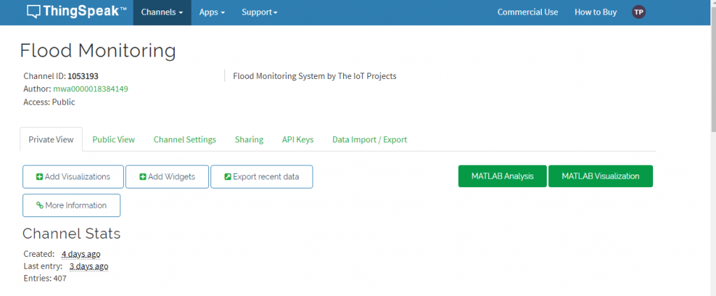
Step 3: Record the credentials
Select the created channel and record the following credentials.
Channel ID, which is at the top of the channel view.
API key, which can be found in the API Key tab of your channel view.
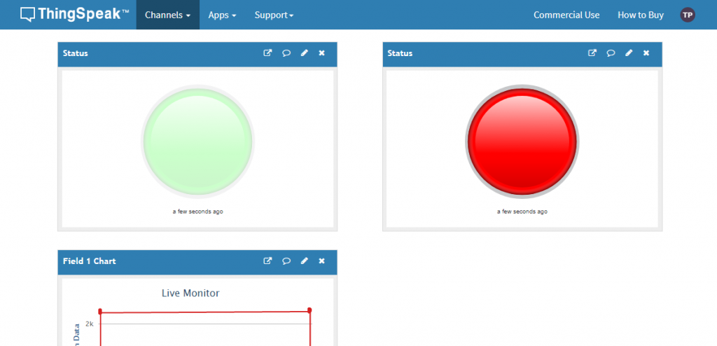
Step 4: Add widgets to your GUI
Click “Add Widgets” and add two appropriate Indicator widgets. In my case, I have taken an indicator of flooding. Choose the appropriate field names for each widget.
Setting up Arduino IDE for NodeMCU Board
After the successful completion of the hardware setup. Now its time to program ESP8266 NodeMCU.
To upload the code to NodeMCU using the Arduino IDE, follow the steps below:
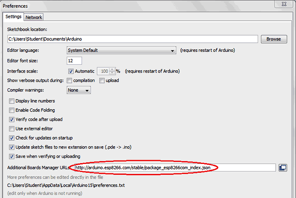
- Open the Ardino IDE, then go to File> Preferences> Settings.
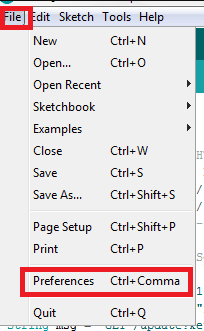
- Paste the URL: https://arduino.esp8266.com/stable/package_esp8266com_index.json in the ‘Additional Board Manager URL‘ field and click ‘Ok’.
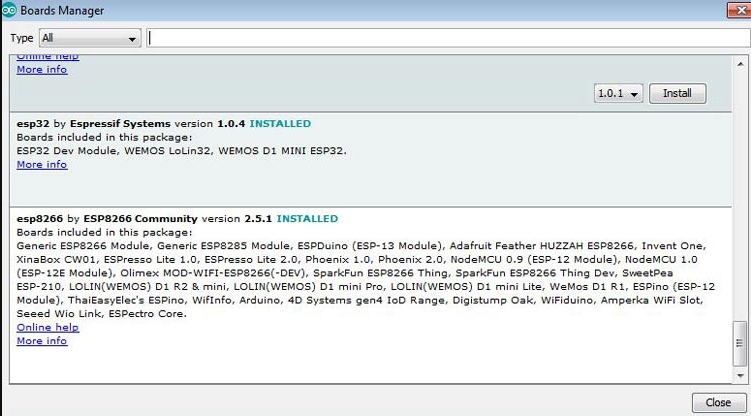
Now. Now go to Tools> Board> Board Manager. In the Boards Manager window, type ESP8266 in the search box, select the new version of the board and click Install.
After successful installation, go to Tools -> Board -> and select NodeMCU 1.0 (ESP-12E Module). Now you can program NodeMCU with Ardino IDE.
After the above setup for programming NodeMCU. You can upload the complete code to ESP8266 NodeMCU. The step-by-step explanation of the full code is provided below.
Program Code explanation
Begin the code by including all the necessary library files in the code for ESP8266 boards. The ThingSpeak.h library is used for the ThingSpeak platform. It can be added to the Arduino IDE using the following steps:
- In the Arduino IDE, choose Sketch/Include Library/Manage Libraries.
- Click the ThingSpeak Library from the list, and click the Install button.
#include "ThingSpeak.h"
#include <ESP8266WiFi.h>
Next, define the pins which are used for the Ultrasonic sensor, Buzzer and LEDs.
#define redled D3
#define grnled D4
#define BUZZER D5 //buzzer pin
Now, Enter the network credentials- i.e. SSID and password of your WiFi Network to connect the NodeMCU with the internet. Then the ThingSpeak account credentials: channel number, API Key, and Author Key. These all credentials were recorded while setting ThingSpeak IoT Platform. Hence, make sure, you have edited these credentials in place of these variables.
unsigned long ch_no = 1053193;//Replace with Thingspeak Channel number
const char * write_api = "1WGTOHK9622G57JI";//Replace with Thingspeak write API
char auth[] = "mwa0000018384149";
char ssid[] = "Alsan Air WiFi 4";
char pass[] = "11122235122@kap1";
The variables are defined for timing purposes.
unsigned long startMillis;
unsigned long currentMillis;
const unsigned long period = 10000;
WiFiClient  client;
long duration1;
int distance1;
Basically, to connect NodeMCU to the internet, we call WiFi.begin function. To Check for the successful network connection WiFi.status() is used. Finally, after a successful connection, we print a message on the Serial Monitor with the NodeMCU IP address.
  Serial.begin(115200);
  WiFi.begin(ssid, pass);
  while (WiFi.status() != WL_CONNECTED)
  {
    delay(500);
    Serial.print(".");
  }
  Serial.println("WiFi connected");
  Serial.println(WiFi.localIP());
Now we connect to the ThingSpeak IoT Platform using Provided credentials. For this, we need to use ThingSpeak.begin function.
ThingSpeak.begin(client);
For calculating the distance, an input pulse is given to the sensor through the trig pin of the HC-SR04 sensor. Here, a 2-microsecond pulse is given, then from the echo pin, the output pulse of the sensor is read. Finally, the distance is calculated in cm.
  digitalWrite(trigPin1, LOW);
  delayMicroseconds(2);
  digitalWrite(trigPin1, HIGH);
  delayMicroseconds(10);
  digitalWrite(trigPin1, LOW);
  duration1 = pulseIn(echoPin1, HIGH);
  distance1 = duration1 * 0.034 / 2;
Then, an if-else condition is defined for the LED indications and Buzzer state for both Normal and Flood conditions. Here as per my setup, I have taken 4 cm as reference. But, you can change it as per your requirements.
  if (distance1 <= 4)
  {
    digitalWrite(D3, HIGH);
    tone(BUZZER, 300);
    digitalWrite(D4, LOW);
    delay(1500);
    noTone(BUZZER);
  }
  else
  {
    digitalWrite(D4, HIGH);
    digitalWrite(D3, LOW);
  }
Finally, the river water level is uploaded to the ThingSpeak channel in interval of 10 seconds.
if (currentMillis - startMillis >= period)
  {
    ThingSpeak.setField(1, distance1);
    ThingSpeak.writeFields(ch_no, write_api);
    startMillis = currentMillis;
  }
Program Sketch/Code
#include "ThingSpeak.h"
#include <ESP8266WiFi.h>
const int trigPin1 = D1;
const int echoPin1 = D2;
#define redled D3
#define grnled D4
#define BUZZER D5 //buzzer pin
unsigned long ch_no = 1053193;//Replace with Thingspeak Channel number
const char * write_api = "1WGTOHK9622G57JI";//Replace with Thingspeak write API
char auth[] = "mwa0000018384149";
char ssid[] = "Alsan Air WiFi 4";
char pass[] = "11122235122@kap1";
unsigned long startMillis;
unsigned long currentMillis;
const unsigned long period = 10000;
WiFiClient  client;
long duration1;
int distance1;
void setup()
{
  pinMode(trigPin1, OUTPUT);
  pinMode(echoPin1, INPUT);
  pinMode(redled, OUTPUT);
  pinMode(grnled, OUTPUT);
  digitalWrite(redled, LOW);
  digitalWrite(grnled, LOW);
  Serial.begin(115200);
  WiFi.begin(ssid, pass);
  while (WiFi.status() != WL_CONNECTED)
  {
    delay(500);
    Serial.print(".");
  }
  Serial.println("WiFi connected");
  Serial.println(WiFi.localIP());
  ThingSpeak.begin(client);
  startMillis = millis();  //initial start time
}
void loop()
{
  digitalWrite(trigPin1, LOW);
  delayMicroseconds(2);
  digitalWrite(trigPin1, HIGH);
  delayMicroseconds(10);
  digitalWrite(trigPin1, LOW);
  duration1 = pulseIn(echoPin1, HIGH);
  distance1 = duration1 * 0.034 / 2;
  Serial.println(distance1);
  if (distance1 <= 4)
  {
    digitalWrite(D3, HIGH);
    tone(BUZZER, 300);
    digitalWrite(D4, LOW);
    delay(1500);
    noTone(BUZZER);
  }
  else
  {
    digitalWrite(D4, HIGH);
    digitalWrite(D3, LOW);
  }
  currentMillis = millis();
  if (currentMillis - startMillis >= period)
  {
    ThingSpeak.setField(1, distance1);
    ThingSpeak.writeFields(ch_no, write_api);
    startMillis = currentMillis;
  }
}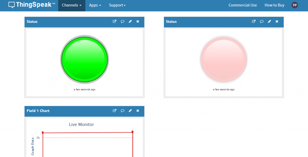
Basically, ThingSpeak will show a big green indicator while there is no flood. and in case of Flood a Red Indicator as shown below:
Wrapping up
This is just a basic model for an IoT Based Flood Monitoring System Using NodeMCU & ThingSpeak. We can improve this project for better performance. Hence, there is a lot of scope for improvising it. I hope you enjoyed the project and learned something new.


when verify the code ” ‘D3’ was not declared in this scope” error is appearing…& what is the char auth[] = “mwa0000018384149”, Can you help me?
This is Auther key of Thingspeak IoT Platform. Read or Watch coding part to know more
i am getting error “D1” was not declared in this scope.Can u please help me with this.
Does this require power supply as you have shown in components power supply but not on breadboard please clarify