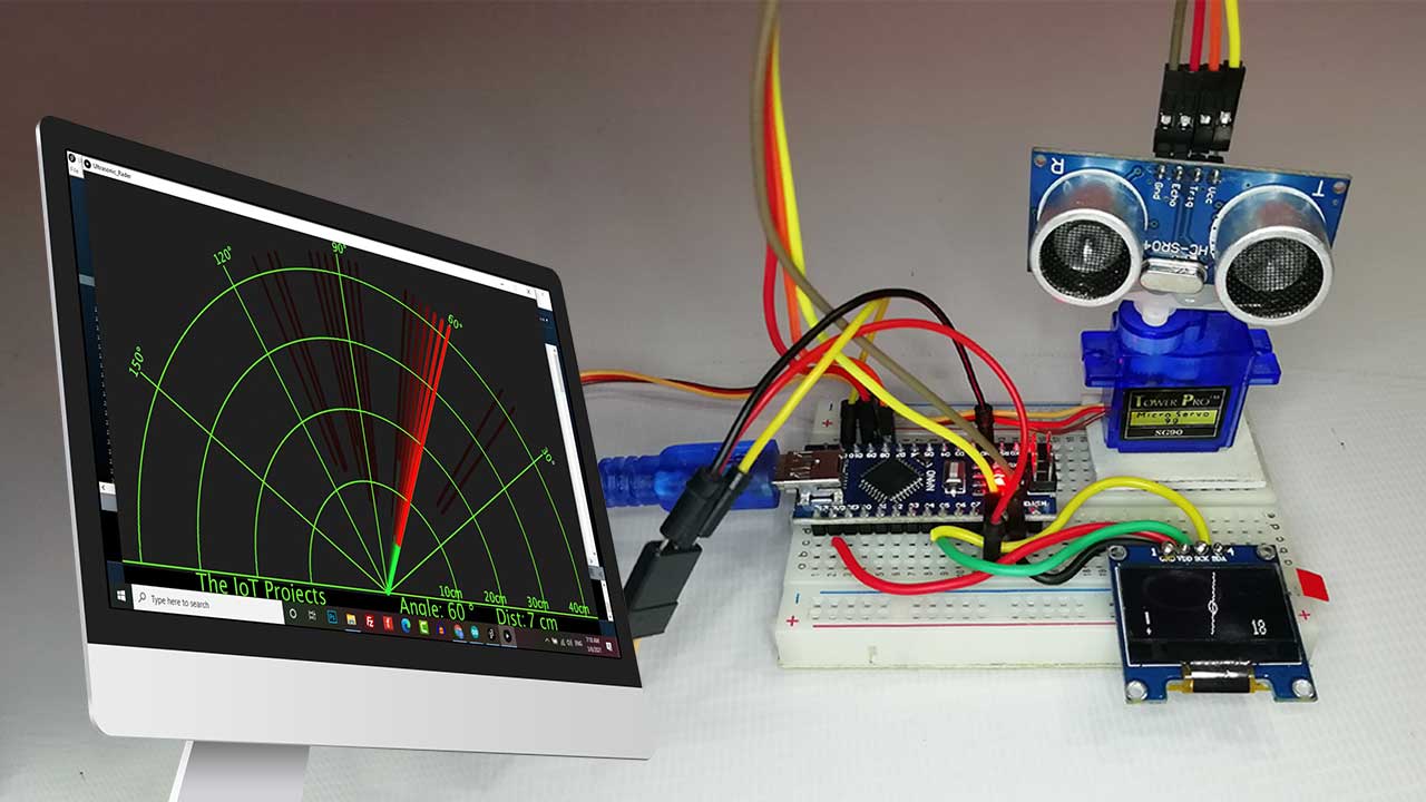
Today we will DIY Portable Radar using Arduino. This is a very interesting and useful project. It can detect any type of object in its range with the help of an ultrasonic sensor. The servo motor helps to rotate the ultrasonic sensor to cover almost all directions. This is a portable version of the Arduino Radar because we have a 0.96-inch OLED display to visualize the data. If any object detected by radar, it will display an alert symbol with a circle on a line and the object’s distance.
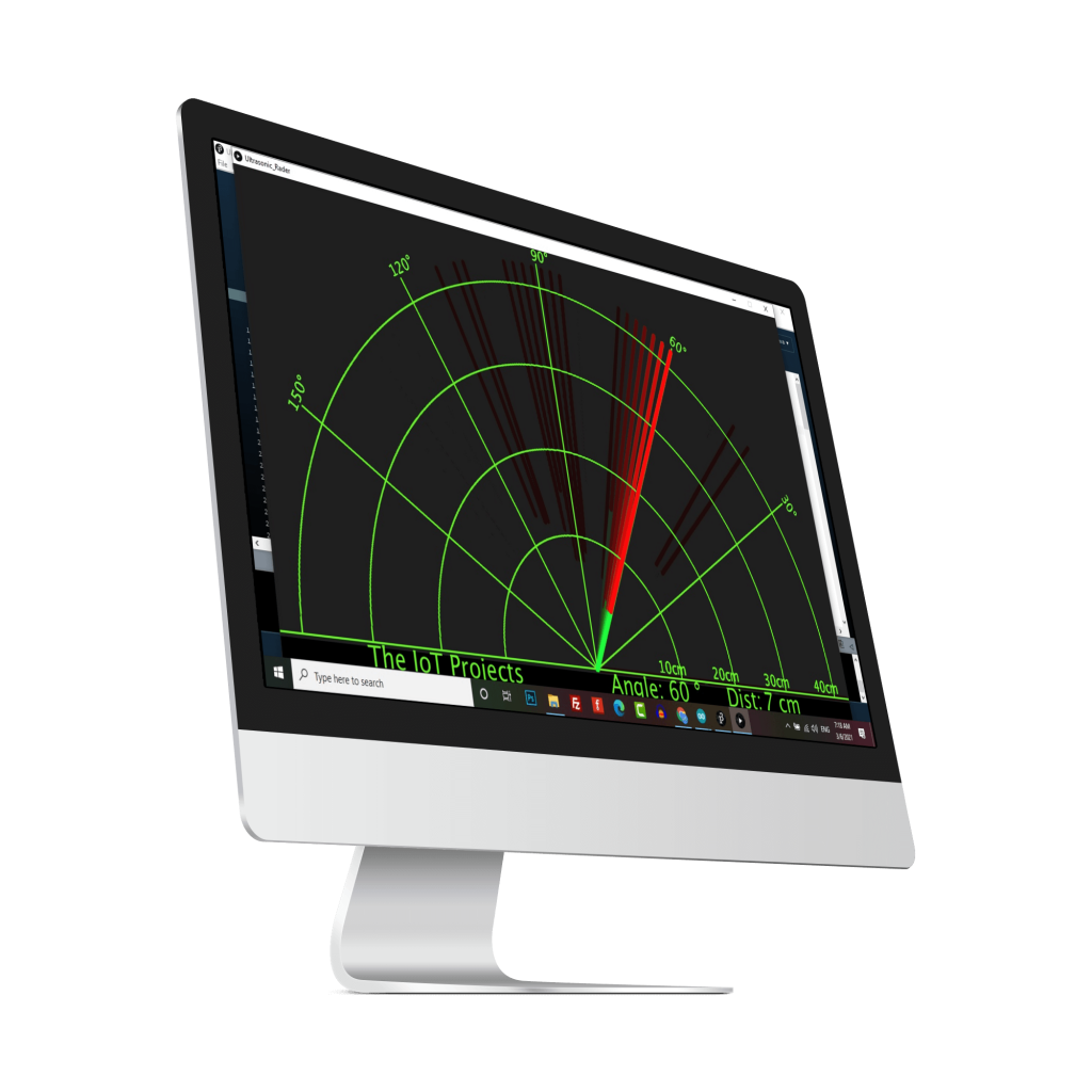
Apart from this, we can use processing IDE software that visualizes all the data on a PC. If any object detected by radar, it will show a red line in the Processing Software. The ultrasonic sensor is very useful in many electronic projects. We use it in distance measuring and object detection. So In this project, we have designed a portable Radar using Ultrasonic Sensor, Servo Motor, & OLED Display for Detection & Ranging.
Table of contents
What is Arduino Radar?
As I mentioned, Radar using Arduino is a popular project. Now let’s understand what actually is it. Arduino Radar is just like a Mini Radar it recognizes the object in its path and displays a circle affected area near the object. So, we call this radar that works on the Ultrasonic frequency. Basically, it consists of an ultrasonic sensor mounted over the servo motor and connected to a 0.96 inch OLED Display. It also has software that shows the output on the computer screen. The interface of this Processing software is pretty the same as the Radar interface.
How Does Portable Radar using Arduino Works?
The ultrasonic sensor in this portable Radar rotates with the servomotor and transmits the ultrasonic waves during this time. Hence, the moving line simulates an angle, and the circle on the same line simulates the distance of an object. Also, the red line affected area is shown in the processing software. If we place any object under the range of the ultrasonic sensor, it detects the object. Basically, the graph interface inside the software becomes red in the object area, while it displays the circle on OLED Display with its exact distance.
The ultrasonic sensor works as an object detector in this Arduino radar project. While OLED Display and processing software make the reaction according to the waves received.
Also Read: Distance Measurement using HC-SR04 Ultrasonic Sensor and Arduino
Actually, the Ultrasonic sensor has two terminals one is a transmitter, and another is the receiver. We know a trigger as the transmitter terminal and the receiver terminal known as the echo.
Here Arduino commands the servo motor to rotate continuously. And transmitter sends the signal parallelly to OLED Display and Processing software to visualize the data. The ultrasonic sensor provides Arduino a unique signal if anything came in its range. Arduino then notifies the display & software for the affected area. So, this project totally depends on Ultrasonic Sensor.
Components Required
The following are the lists of the required components to build Portable Radar using Arduino. You can purchase them from Amazon.
| S.N | Components Name | Description | Quantity | |
|---|---|---|---|---|
| 1 | Arduino Nano | Arduino Nano R3 | 1 | https://amzn.to/3swvBuO |
| 2 | Servo Motor | Micro Servo - SG90 | 1 | https://amzn.to/2NRXXAy |
| 3 | Ultrasonic Sensor | SC-SR04 Sensor | 1 | https://amzn.to/3kOg335 |
| 4 | OLED Display | 0.96 Inch OLED Display | 1 | https://amzn.to/3pGssa7 |
| 5 | Jumper Wires | Jumper Cables breadboard friendly | 15 | https://amzn.to/2JWSR44 |
| 6 | Breadboard | Mini Breadboard | 1 | https://amzn.to/2NP2UKL |
Circuit Diagram of Arduino Radar
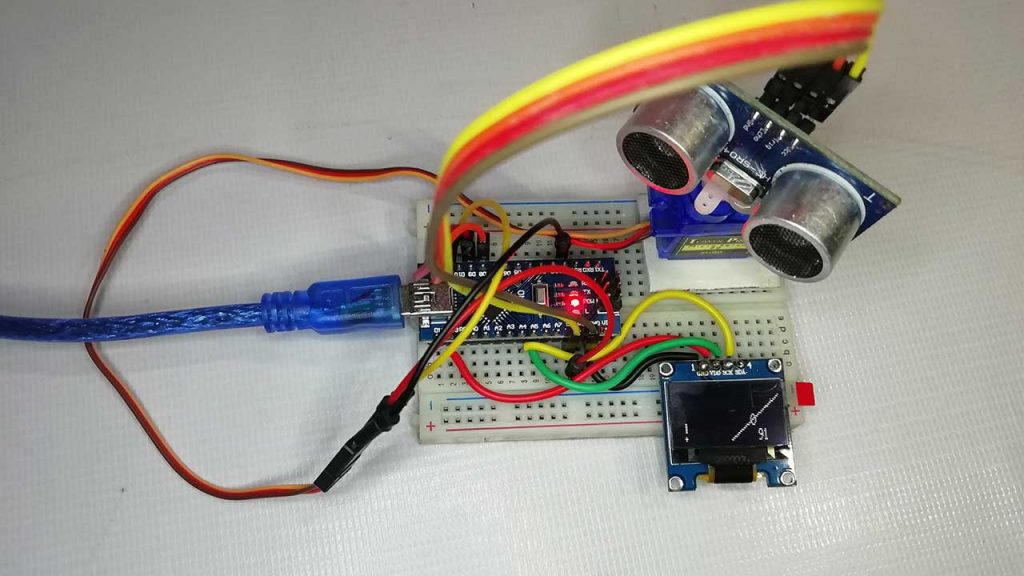
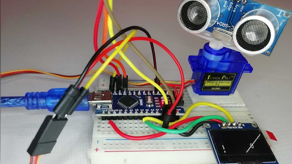
Now lets wire Ultrasonic Sensor, Servo and OLED Display with Arduino. The Connections are fairly simple. Connect the components as shown in the schematics below.
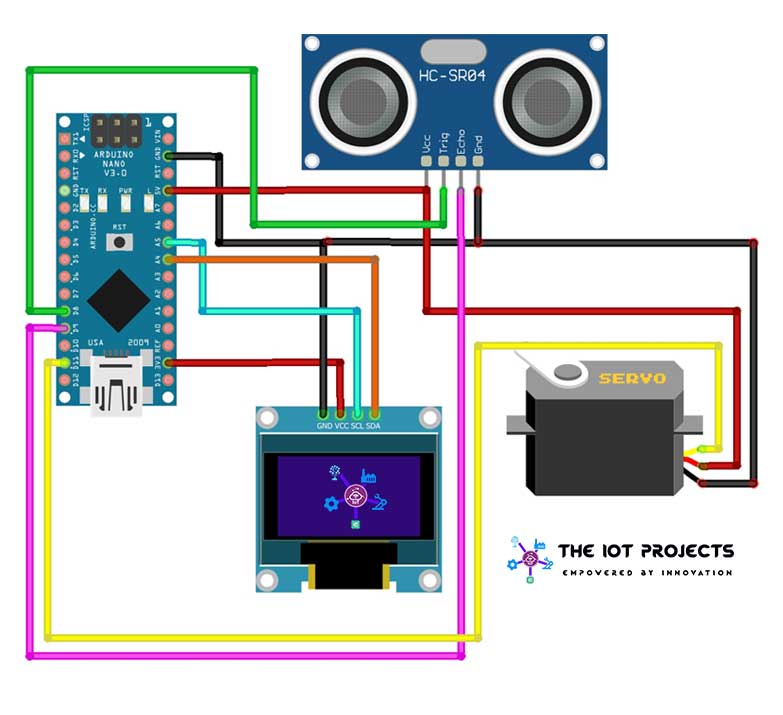
| S.N | Ultrasonic Sensor | Arduino |
| 1 | VCC | 5V |
| 2 | GND | GND |
| 3 | Trig | Pin 8 |
| 4 | ECHO | Pin 9 |
| S.N | Servo Motor | Arduino |
| 1 | VCC | 5V |
| 2 | GND | GND |
| 3 | Signal | Pin 11 |
| S.N | OLED Display | Arduino |
| 1 | GND | GND |
| 2 | VCC | 3.3V |
| 3 | SCL | A5 |
| 4 | SDA | A4 |
I have assembled the circuit on a breadboard. If you don’t want to assemble the circuit on a breadboard and want Custom PCB for the project, then here is the PCB for you. The PCB Board for the portable Arduino Radar is designed for you. You can simply download the Gerber file from the link below and order the PCB online from PCBWay

PCBWay offers Only $5 for 10 PCBs and a total of $30 dollars for 20 PCBs Assembly. Apart from this PCBWay offers $5 as a signup bonus. So, what are you waiting for? get your first prototype order for free.
Programming Arduino for Radar Project
To program the Arduino, Ultrasonic Sensor, OLED & Servo Motor with Arduino IDE, we need to install the the following libraries.
 #include <SPI.h>
 #include <Wire.h>
 #include <Adafruit_GFX.h>
 #include <Adafruit_SSD1306.h>
 #include <Servo.h>
Then we defined the Trig and Echo pin of Ultrasonic Sensor
 #define Trig 8
 #define Echo 9
We initialize the OLED Display with the I2C address of 0x3C
display.begin(SSD1306_SWITCHCAPVCC, 0x3C);Started the serial port for processing IDE.
Serial.begin(9600);Defined the servo attach pin.
Servo1.attach(11);Start the Display with Arduino Radar Welcome message.
   display.clearDisplay();
   display.setTextSize(1);
   display.setTextColor(WHITE);
   display.setCursor(20, 10);
   display.println("Arduino RADAR");
   display.display();
   delay(2000);
Defined Long variables.
long distance, duration, Distance;We Define the Loop variables
int i, j, k, l, m, n; Loop for moving the line from centre left to top left
for (i = 10; i >= 0; i -= 2)Map the servo values
int servomap = map(i, 0, 10, 60, 40); Get the distance sensor value by calling the function
Distance = Distance_value();Serial Print for processing IDE
     Serial.print(servomap); // Sends the current degree into the Serial Port
     Serial.print(","); // Sends addition character right next to the previous value needed later in the Processing IDE for indexing
     Serial.print(Distance); // Sends the distance value into the Serial Port
     Serial.print("."); // Sends addition character right next to the previous value needed later in the Processing IDE for indexing
if object is out of range (no circle will be displayed on the line
if (Distance > 40 )
 {
display.clearDisplay();
Servo1.write(servomap);
display.drawLine(64, 32, 0, i, WHITE );    //draw a line   display.display();
delay(100);
}
if object is in range, map funtion for draw circle at exact location of the object, draw line, draw object location circle, and object detection sign.
else if (Distance >= 0 && Distance <= 40)  //if object is in range
     {
       int xmap1 = map(Distance, 0, 40, 64, 0);    //map funtion for draw circle at exact location of the object
       int ymap1 = map(Distance, 0, 40, 32, i);
       display.clearDisplay();
       Servo1.write(servomap);
       display.drawLine(64, 32, 0, i, WHITE );    //draw line
       display.drawCircle(xmap1, ymap1, 3, WHITE);  //draw object location circle
       display.fillCircle(10, 30, 1, WHITE);    //object detection sign
       display.fillRoundRect(10, 20, 2, 8, 2, WHITE);  //object detection sign
       display.display();
       delay(100);
     }
This is the funtion to get the distance value and display it on the SSD1306 OLED Dispaly.
int Distance_value()
 {
   digitalWrite(Trig, LOW);
   delayMicroseconds(2);
   digitalWrite(Trig, HIGH);
   delayMicroseconds(10);
   digitalWrite(Trig, LOW);
   duration = pulseIn(Echo, HIGH);
   distance = (duration / 2) / 29.1;
   display.setTextSize(1);
   display.setTextColor(WHITE);
   display.setCursor(100, 25);
   display.println(distance);
   delay(15);
   display.display();
   return distance;
 }
Program Code for Arduino Radar
So, this is the final program code for Portable Arduino Radar. Copy the code provided below and upload it to your Arduino Board.
 #include <SPI.h>
 #include <Wire.h>
 #include <Adafruit_GFX.h>
 #include <Adafruit_SSD1306.h>
 #include <Servo.h>
 #define Trig 8
 #define Echo 9
 Adafruit_SSD1306 display(-1);
 Servo Servo1;
 void setup()
 {
   // initialize with the I2C addr 0x3C
   display.begin(SSD1306_SWITCHCAPVCC, 0x3C);
   pinMode(Trig, OUTPUT);
   pinMode(Echo, INPUT);
   Serial.begin(9600);
   Servo1.attach(11);
   delay(1000);
   Servo1.write(40);
   display.clearDisplay();
   display.setTextSize(1);
   display.setTextColor(WHITE);
   display.setCursor(20, 10);
   display.println("Arduino RADAR");
   display.display();
   delay(2000);
 }
 long distance, duration, Distance;
 void loop() {
 int i, j, k, l, m, n;  //Define Loop variables
 for (i = 10; i >= 0; i -= 2)         //loop for moving the line from centre left to top left
   {
     int servomap = map(i, 0, 10, 60, 40);   //map the servo values
     Distance = Distance_value();  //get the distance sensor value by calling the function
 // Serial Print for processing IDE
Serial.print(servomap); // Sends the current degree into the Serial Port Serial.print(","); // Sends addition character right next to the previous value needed later in the Processing IDE for indexing Serial.print(Distance); // Sends the distance value into the Serial Port Serial.print("."); // Sends addition character right next to the previous value needed later in the Processing IDE for indexing if (Distance > 40 )   //if object is out of range (no circle will be displayed on the line
{
display.clearDisplay();
Servo1.write(servomap);
display.drawLine(64, 32, 0, i, WHITE );    //draw a line   display.display();
delay(100);
}
else if (Distance >= 0 && Distance <= 40)  //if object is in range
{
 int xmap1 = map(Distance, 0, 40, 64, 0);    //map funtion for draw circle at exact location of the object
int ymap1 = map(Distance, 0, 40, 32, i);
display.clearDisplay();
Servo1.write(servomap);
display.drawLine(64, 32, 0, i, WHITE );    //draw line   display.drawCircle(xmap1, ymap1, 3, WHITE);  //draw object location circle
display.fillCircle(10, 30, 1, WHITE);    //object detection sign   display.fillRoundRect(10, 20, 2, 8, 2, WHITE);  //object detection sign
display.display();
delay(100);
}
 }
   for (j = 0; j <= 128; j += 4) //moving from left to right
   {
     int servomap = map(j, 0, 128, 61, 120);
     Distance = Distance_value();
 //Serial Print for Processing IDE
Serial.print(servomap); // Sends the current degree into the Serial Port Serial.print(","); // Sends addition character right next to the previous value needed later in the Processing IDE for indexing Serial.print(Distance); // Sends the distance value into the Serial Port Serial.print("."); // Sends addition character right next to the previous value needed later in the Processing IDE for indexing
if (Distance > 40 )
{
display.clearDisplay();
Servo1.write(servomap);
display.drawLine(64, 32, j, 0, WHITE );
display.display();
delay(100);
}
else if (Distance >= 0 && Distance <= 40)
{
int xmap2 = map(Distance, 0, 40, 64, j);
int ymap2 = map(Distance, 0, 40, 32, 0);
display.clearDisplay();
Servo1.write(servomap);
display.drawLine(64, 32, j, 0, WHITE );
display.drawCircle(xmap2, ymap2, 3, WHITE);
display.fillCircle(10, 30, 1, WHITE);
display.fillRoundRect(10, 20, 2, 8, 2, WHITE);
display.display();
delay(100);
}
 }
   for (k = 0; k <= 10 ; k += 2) //moving from top right to centre right
   {
     int servomap = map(k, 0, 10, 121, 140);
     Distance = Distance_value();
 //Serial Print for Processing IDE
Serial.print(servomap); // Sends the current degree into the Serial Port Serial.print(","); // Sends addition character right next to the previous value needed later in the Processing IDE for indexing Serial.print(Distance); // Sends the distance value into the Serial Port Serial.print("."); // Sends addition character right next to the previous value needed later in the Processing IDE for indexing
if (Distance > 40 ) {
display.clearDisplay();
Servo1.write(servomap);
display.drawLine(64, 32, 128, k, WHITE );
display.display();
delay(100);
}
else if (Distance >= 0 && Distance <= 40)
{
int xmap3 = map(Distance, 0, 40, 64, 128);
int ymap3 = map(Distance, 0, 40, 32, k);
 display.clearDisplay();
Servo1.write(servomap);
display.drawLine(64, 32, 128, k, WHITE );
display.drawCircle(xmap3, ymap3, 3, WHITE);
display.fillCircle(10, 30, 1, WHITE);
display.fillRoundRect(10, 20, 2, 8, 2, WHITE);
display.display();
delay(100);
}
 }
   for (l = 10; l >= 0 ; l -= 2) //reserve loops
   {
     int servomap = map(l, 10, 0, 140, 120);
     Distance = Distance_value();
 //Serial Print for Processing IDE
Serial.print(servomap); // Sends the current degree into the Serial Port Serial.print(","); // Sends addition character right next to the previous value needed later in the Processing IDE for indexing Serial.print(Distance); // Sends the distance value into the Serial Port Serial.print("."); // Sends addition character right next to the previous value needed later in the Processing IDE for indexing
if (Distance > 40 ) {
display.clearDisplay();
Servo1.write(servomap);
display.drawLine(64, 32, 128, l, WHITE );
display.display();
delay(100);
}
else if (Distance >= 0 && Distance <= 40)
{
int xmap3 = map(Distance, 0, 40, 64, 128);
 int ymap3 = map(Distance, 0, 40, 32, l);
display.clearDisplay();
Servo1.write(servomap);
display.drawLine(64, 32, 128, l, WHITE );
 display.drawCircle(xmap3, ymap3, 3, WHITE);
display.fillCircle(10, 30, 1, WHITE);
display.fillRoundRect(10, 20, 2, 8, 2, WHITE);
display.display();
delay(100);
}
 }
   for (m = 128; m >= 0; m -= 4)
   {
     int servomap = map(m, 128, 0, 121, 60);
     Distance = Distance_value();
 //Serial Print for Processing IDE
Serial.print(servomap); // Sends the current degree into the Serial Port Serial.print(","); // Sends addition character right next to the previous value needed later in the Processing IDE for indexing Serial.print(Distance); // Sends the distance value into the Serial Port Serial.print("."); // Sends addition character right next to the previous value needed later in the Processing IDE for indexing
if (Distance > 40 ) {
display.clearDisplay();
Servo1.write(servomap);
display.drawLine(64, 32, m, 0, WHITE );
display.display();
delay(100);
}
else if (Distance >= 0 && Distance <= 40)
{
int xmap2 = map(Distance, 0, 40, 64, m);
int ymap2 = map(Distance, 0, 40, 32, 0);
display.clearDisplay();
Servo1.write(servomap);
display.drawLine(64, 32, m, 0, WHITE );
display.drawCircle(xmap2, ymap2, 3, WHITE);
display.fillCircle(10, 30, 1, WHITE);
display.fillRoundRect(10, 20, 2, 8, 2, WHITE);
 display.display();   delay(100); }
 }
   for (n = 0; n <= 10; n += 2)
   {
     int servomap = map(n, 0, 10, 61, 40);
     Distance = Distance_value();
 //Serial Print for Processing IDE
Serial.print(servomap); // Sends the current degree into the Serial Port Serial.print(","); // Sends addition character right next to the previous value needed later in the Processing IDE for indexing Serial.print(Distance); // Sends the distance value into the Serial Port Serial.print("."); // Sends addition character right next to the previous value needed later in the Processing IDE for indexing
if (Distance > 40 )
{
display.clearDisplay();
Servo1.write(servomap);
display.drawLine(64, 32, 0, n, WHITE );
display.display();
delay(100);
}
else if (Distance >= 0 && Distance <= 40)
 {
int xmap1 = map(Distance, 0, 40, 64, 0);
int ymap1 = map(Distance, 0, 40, 32, n);
display.clearDisplay();
Servo1.write(servomap);
display.drawLine(64, 32, 0, n, WHITE );
display.drawCircle(xmap1, ymap1, 3, WHITE);
display.fillCircle(10, 30, 1, WHITE);
display.fillRoundRect(10, 20, 2, 8, 2, WHITE);
display.display();
delay(100);
}
 }
 }
 int Distance_value()  //funtion to get the distance value
 {
   digitalWrite(Trig, LOW);
   delayMicroseconds(2);
   digitalWrite(Trig, HIGH);
   delayMicroseconds(10);
   digitalWrite(Trig, LOW);
   duration = pulseIn(Echo, HIGH);
   distance = (duration / 2) / 29.1;
   display.setTextSize(1);
   display.setTextColor(WHITE);
   display.setCursor(100, 25);
   display.println(distance);  //display distance value on oled display
   delay(15);
   display.display();
   return distance; //return the distance value
 }
Processing IDE & Code
Now you have to download a processing software from the link provided below:
Here we are sharing the Processing IDE code which you have to upload to the software.
Note:- You need to mention the port in the processing software code given below. This is the port at which your Arduino is connected.
import processing.serial.; // imports library for serial communication
import java.awt.event.KeyEvent; // imports library for reading the data from the serial port
import java.io.IOException;
Serial myPort; // defines Object Serial
// defubes variables
 String angle="";
String distance="";
String data="";
String noObject;
float pixsDistance;
int iAngle, iDistance;
int index1=0;
int index2=0;
PFont orcFont;
void setup() {
size (1280, 720); // CHANGE THIS TO YOUR SCREEN RESOLUTION
   smooth();
   myPort = new Serial(this,"COM7", 9600); // starts the serial communication
   myPort.bufferUntil('.'); // reads the data from the serial port up to the character '.'. So actually it reads this: angle,distance.
  }
  void draw() {
   fill(98,245,31);
   // simulating motion blur and slow fade of the moving line
   noStroke();
   fill(0,4);
   rect(0, 0, width, height-height0.065);
   fill(98,245,31); // green color
   // calls the functions for drawing the radar
   drawRadar();
   drawLine();
   drawObject();
   drawText();
  }
  void serialEvent (Serial myPort) { // starts reading data from the Serial Port
   // reads the data from the Serial Port up to the character '.' and puts it into the String variable "data".
   data = myPort.readStringUntil('.');
   data = data.substring(0,data.length()-1);
   index1 = data.indexOf(","); // find the character ',' and puts it into the variable "index1"
   angle= data.substring(0, index1); // read the data from position "0" to position of the variable index1 or thats the value of the angle the Arduino Board sent into the Serial Port
   distance= data.substring(index1+1, data.length()); // read the data from position "index1" to the end of the data pr thats the value of the distance
   // converts the String variables into Integer
   iAngle = int(angle);
   iDistance = int(distance);
  }
  void drawRadar() {
   pushMatrix();
   translate(width/2,height-height0.074); // moves the starting coordinats to new location     noFill();     strokeWeight(2);     stroke(98,245,31);     // draws the arc lines     arc(0,0,(width-width0.0625),(width-width0.0625),PI,TWO_PI);     arc(0,0,(width-width0.27),(width-width0.27),PI,TWO_PI);     arc(0,0,(width-width0.479),(width-width0.479),PI,TWO_PI);     arc(0,0,(width-width0.687),(width-width0.687),PI,TWO_PI);     // draws the angle lines     line(-width/2,0,width/2,0);     line(0,0,(-width/2)cos(radians(30)),(-width/2)sin(radians(30)));     line(0,0,(-width/2)cos(radians(60)),(-width/2)sin(radians(60)));     line(0,0,(-width/2)cos(radians(90)),(-width/2)sin(radians(90)));     line(0,0,(-width/2)cos(radians(120)),(-width/2)sin(radians(120)));     line(0,0,(-width/2)cos(radians(150)),(-width/2)sin(radians(150)));     line((-width/2)cos(radians(30)),0,width/2,0);
   popMatrix();
  }
  void drawObject() {
   pushMatrix();
   translate(width/2,height-height0.074); // moves the starting coordinats to new location     strokeWeight(9);     stroke(255,10,10); // red color     pixsDistance = iDistance((height-height0.1666)0.025); // covers the distance from the sensor from cm to pixels
   // limiting the range to 40 cms
   if(iDistance<40){
    // draws the object according to the angle and the distance
   line(pixsDistancecos(radians(iAngle)),-pixsDistancesin(radians(iAngle)),(width-width0.505)cos(radians(iAngle)),-(width-width0.505)sin(radians(iAngle)));
   }
   popMatrix();
  }
  void drawLine() {
   pushMatrix();
   strokeWeight(9);
   stroke(30,250,60);
   translate(width/2,height-height0.074); // moves the starting coordinats to new location     line(0,0,(height-height0.12)cos(radians(iAngle)),-(height-height0.12)sin(radians(iAngle))); // draws the line according to the angle     popMatrix();    }    void drawText() { // draws the texts on the screen     pushMatrix();     if(iDistance>40) {     noObject = "Out of Range";     }     else {     noObject = "In Range";     }     fill(0,0,0);     noStroke();     rect(0, height-height0.0648, width, height);
   fill(98,245,31);
   textSize(25);
   text("10cm",width-width0.3854,height-height0.0833);
   text("20cm",width-width0.281,height-height0.0833);
   text("30cm",width-width0.177,height-height0.0833);
   text("40cm",width-width0.0729,height-height0.0833);
   textSize(40);
   text("The IoT Projects ", width-width0.875, height-height0.0277);
   text("Angle: " + iAngle +" °", width-width0.48, height-height0.0277);
   text("Dist: ", width-width0.26, height-height0.0277);
   if(iDistance<40) {
   text("    " + iDistance +" cm", width-width0.225, height-height0.0277);
   }
   textSize(25);
   fill(98,245,60);
   translate((width-width0.4994)+width/2cos(radians(30)),(height-height0.0907)-width/2sin(radians(30)));
   rotate(-radians(-60));
   text("30°",0,0);
   resetMatrix();
   translate((width-width0.503)+width/2cos(radians(60)),(height-height0.0888)-width/2sin(radians(60)));
   rotate(-radians(-30));
   text("60°",0,0);
   resetMatrix();
   translate((width-width0.507)+width/2cos(radians(90)),(height-height0.0833)-width/2sin(radians(90)));
   rotate(radians(0));
   text("90°",0,0);
   resetMatrix();
   translate(width-width0.513+width/2cos(radians(120)),(height-height0.07129)-width/2sin(radians(120)));
   rotate(radians(-30));
   text("120°",0,0);
   resetMatrix();
   translate((width-width0.5104)+width/2cos(radians(150)),(height-height0.0574)-width/2sin(radians(150)));
   rotate(radians(-60));
   text("150°",0,0);
   popMatrix();
  }
Now click on RUN to start the processing IDE For Arduino Radar visualization.
Demonstration of Arduino Radar Project
The video demonstration of Portable Radar using Arduino, ultrasonic sensor, servo motor, and OLED Display is embedded below. If you like the video don’t forget to hit that like button.
Wrapping Up
So, that’s all for Portable Radar Project using Arduino. I wish you all the best for the project. if you stuck anywhere you can ask me in the comment section below.


Hi,
Thanks for the tutorial. I have some problems with the Processing IDE code as when I copy and paste it, for line 26:
rect(0, 0, width, height-height0.065);
I get the following message
The variable “height0” does not exist
Unexpected token: .065
Please advise.