Home Automation with ESP8266 Web Server & Relay Module Control Appliances from Local Network
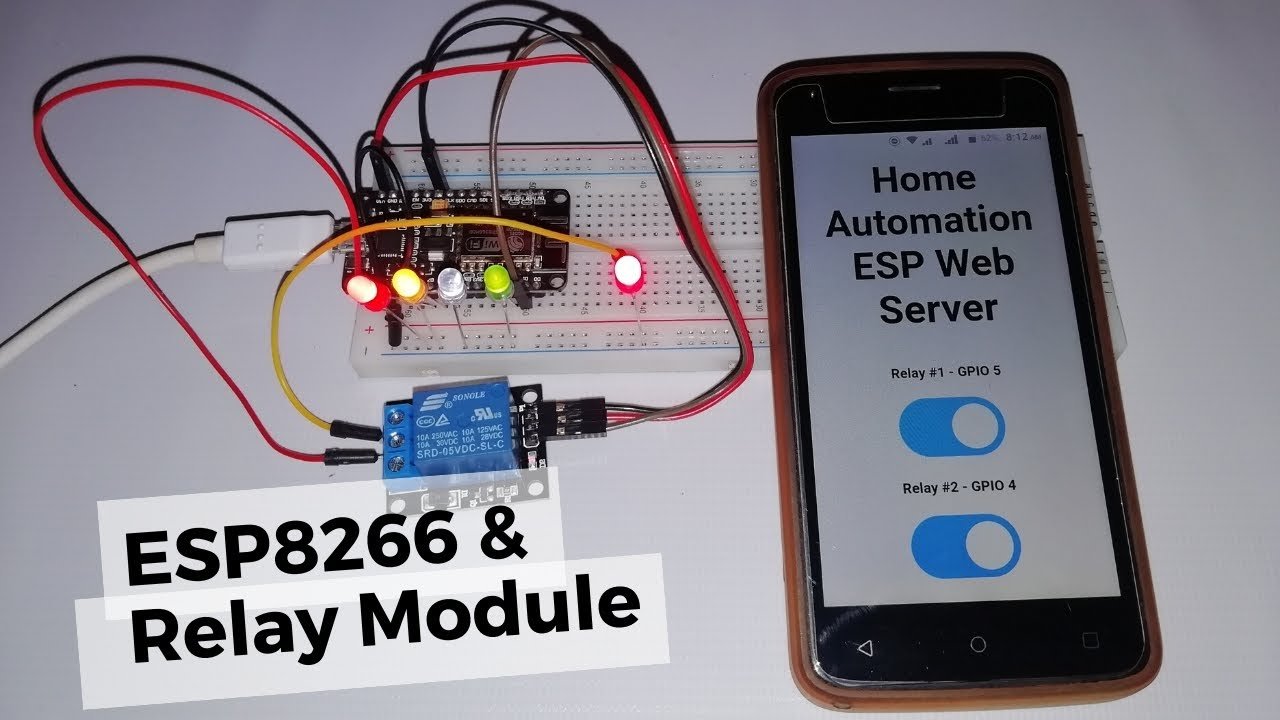
Today we will build Home Automation with ESP8266 Web Server & Relay Module Control Home Appliances from Local Network. Using relays with the ESP8266 is the best way to remotely control AC home appliances. This tutorial describes how to control the relay module with ESP8266 NodeMCU. Basically, We will build a web server to see how the relay module works, how to connect relay to the ESP8266, and control a relay (or as many relays as you want) remotely.
- Video Demonstration-Home Automation with ESP8266 Web Server
- Introduction to Relays
- ESP8266 Safest Pins to Use with Relays
- Circuit Diagram-Home Automation with ESP8266, Relay Module
- Arduino Sketch – Home Automation with ESP8266 Web Server & Relay Module.
- Control Multiple Relays with ESP8266 NodeMCU Web Server
- Interfacing 2 Channel Relay to ESP8266 NodeMCU
- Demonstration
- Wrapping Up
Video Demonstration-Home Automation with ESP8266 Web Server
Watch the video tutorial below or continue reading for written instructions, Schematic Diagram, and Source Codes.
We have few more interesting Projects based on ESP8266
Introduction to Relays
A relay is an electrically operated switch. Usually, like any other switch, it can be turned on or off, with or without current. It can be controlled through low voltages such as 3.3V provided by ESP8266 GPIOs and helps to control high voltages. Such as 12v, 24V, or mains voltage ( 220V or 240V).
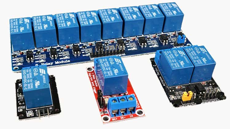
Types of Relays
In the market or Online shopping sites, different relay modules with different numbers of channels are found. You can find relay modules with one, two, four, eight, and sixteen channels. The number of channels determines the number of outputs we can control.
There are some relay modules whose electromagnets can be powered by 5V and with 3.3V. Basically, Both are usable with the ESP8266 – you can either use the Vin pin for 5V or the 3.3V pin.
Additionally, some come with a built-in optocoupler that adds an extra “layer” of protection, optically isolating the ESP8266 from the relay circuit.
Here we have some more Projects that you may like:
Relay Pinouts
For demonstration purposes, let’s see the pinout of a 2-channel relay module. However, the process of using a relay module with a different number of channels are similar.
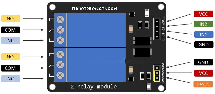
The two connectors (with three sockets each) on the left side of the relay module is for connecting high voltage. Other pins on the right side (low-voltage) for connecting to the ESP8266 GPIOs.
Mains Voltage Connections of Relay
The relay module shown in the below photo has two connectors, each of them has three sockets: common (COM), Normally Closed (NC), and Normally Open (NO).
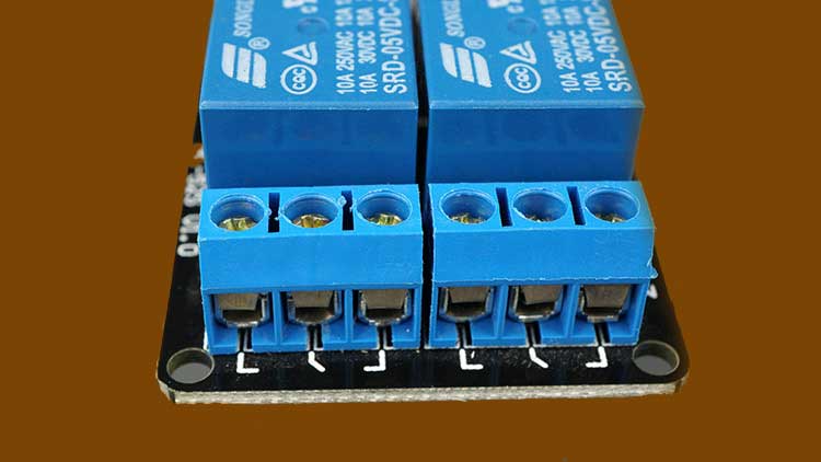
- COM: main voltage connection (current that you want to control).
- NC (Normally Closed): In normally closed configuration the relay is closed by default. The NC and COM pins are connected, which means the current is flowing until you send a signal from the ESP8266 to the relay module. To open the circuit and stop the flow of current.
- NO (Normally Open): In the normally open configuration there is no connection between the NO and COM pins. Hence, the circuit is broken until and unless you send a signal from the ESP8266 to close the circuit.
Relay Control Pins
Further, In the 2-Channel relay module, the low-voltage side has a set of four pins. Consists of VCC and GND to power up the module, and input 1 (IN1) and input 2 (IN2) to control the relays, respectively.
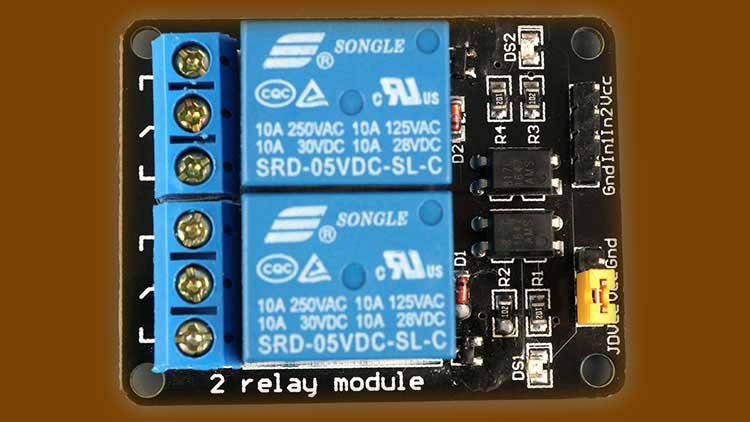
If you have one channel relay, you’ll have just one input pin. If you have 4-channels relay, you’ll have 4input pins, and so on.
The signal that we send to the IN pins, determines whether the relay is active or not. When the input goes below about 2V The relay is triggered. This means that you’ll see the following conditions:
- In Normally Closed configuration (NC):
- HIGH signal – current is flowing
- LOW signal – current is not flowing
- In Normally Open configuration (NO):
- HIGH signal – current is not flowing
- LOW signal – current is flowing
Note: we should use a normally closed configuration when the current is needed to be flowing most of the time. And you want to stop it occasionally.
Similarly, use a normally open configuration when current should flow occasionally. (For example: Turn on lamp or fan when required).
Power Supply Selection
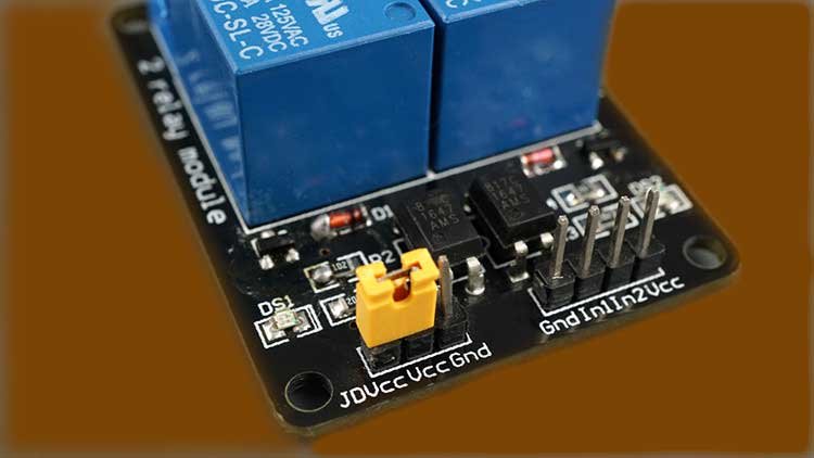
Now, the second set consists of GND, VCC, and JD-VCC pins. The JD-VCC pin is used for powering the electromagnet of the relay. In the above image, you can see a jumper cap connecting the VCC and JD-VCC pins. My relay has a yellow cap, but you may have a different color.
By default, the VCC and JD-VCC pins are connected by the cap. which means, the relay electromagnet is directly powered from the ESP8266 power pin. Hence they are not physically isolated.
Removing the Jumper cap, Nee independent power source to power up the relay electromagnet through JD-VCC pin. Actually, this configuration physically isolates relays from NodeMCU. It has built-in optocoupler to prevent ESP8266 damage in the case of electrical spikes.
ESP8266 Safest Pins to Use with Relays
Basically, when ESP8266 boots some of its pins output a 3.3V signal. So this may create a problem, if you connect relays or other peripherals to those GPIOs. Additionally, In order to boot ESP8266, some pins must be pulled either High or Low.
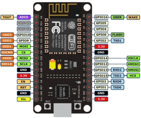
Hence, the safest ESP8266 pins to interface with relays are: GPIO 5, GPIO 4, GPIO 14, GPIO 12 and GPIO 13.
Circuit Diagram-Home Automation with ESP8266, Relay Module
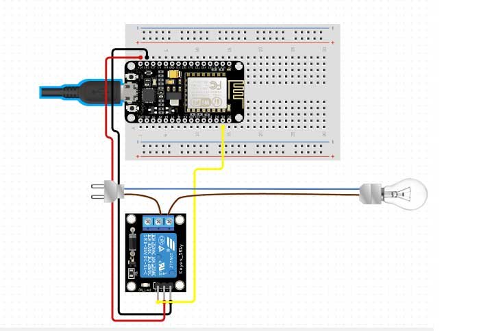
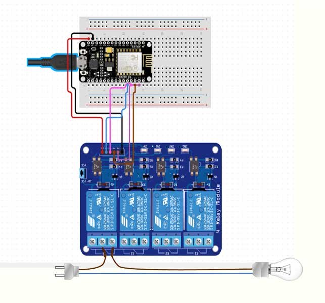
Connect the relay module to the ESP8266 as shown in the following schematic diagram. The diagram shows the wiring for a 1-channel relay module and 4-Channel Module. Wiring a different number of channels is similar.
Warning: in this example, we’re dealing with mains voltage. Misuse can result in serious injuries. If you’re unknown with mains voltage, ask someone who can help you out. While programming the ESP8266 or wiring your circuit, make sure you have disconnected everything from the main voltage.
Alternatively, you can use a 12V battery to control 12V appliances.
In this example, we’re controlling a bulb. We just want to light up the bulb occasionally, so it is better to use a normally open configuration.
We’re connecting the Input 1 pin to GPIO 5, you can use any other suitable GPIO.
Arduino Sketch – Home Automation with ESP8266 Web Server & Relay Module.
The code to control a relay with the ESP8266 is very simple and easy. In this example, as we’re using a NO configuration. Hence, we need to send a High signal to stop the current flow, and a Low signal to let the current flow.
Actually, this code will light up and OFF your bulb for 10 seconds. Which means the bulb will glow for 10 seconds and goes off for 10 seconds and respectively.
const int relay = 5;

void setup() {
  Serial.begin(115200);
  pinMode(relay, OUTPUT);
}

void loop() {
  // Normally Open configuration, send LOW signal to let current flow
  // (if you're usong Normally Closed configuration send HIGH signal)
  digitalWrite(relay, LOW);
  Serial.println("Current Flowing");
  delay(5000);

  // Normally Open configuration, send HIGH signal stop current flow
  // (if you're usong Normally Closed configuration send LOW signal)
  digitalWrite(relay, HIGH);
  Serial.println("Current not Flowing");
  delay(5000);
}
Program Code Explanation
Define the relay IN pin is connected to ESP8266.
const int relay = 5;In the setup(), we defined the relay as an output.
pinMode(relay, OUTPUT);In the loop(), we send a LOW signal to let the current flow and light up the bulb.
digitalWrite(relay, LOW);If you’re using a NC configuration, send a HIGH signal to light up the bulb. Then, wait 5 seconds.
delay(5000); Stop the current flow by sending a HIGH signal to the relay pin connected to ESP8266. If you’re using an NC configuration, send a LOW signal to stop the flow of current.
digitalWrite(relay, HIGH);Control Multiple Relays with ESP8266 NodeMCU Web Server
In this example, we’ve created a web server that allows you to control as many relays as you want through webserver. whether they are configured as NO or as NC. Basically, you just need to change a few lines of a sketch to define the number of relays you want to control. But, you need to change or define the pin assignment to the project.
To build the above shown web server, we use the ESPAsyncWebServer library.
Installing the ESPAsyncWebServer library
Follow these steps to install the ESPAsyncWebServer library:
- Download the ESPAsyncWebServer library. It is basically a zip file.
- Unzip the .zip folder
- Rename your folder from
ESPAsyncWebServer-masterto ESPAsyncWebServer. - Move the ESPAsyncWebServer folder to your Arduino IDE installation libraries folder.
Alternatively, Open your Arduino IDE, Go to Sketch > Include Library > Add.ZIP library… and select the library you’ve just downloaded.
This is the easiest any simple method to add Libraries to your Arduino IDE.
Installing the ESPAsyncTCP Library for ESP8266
The ESPAsyncWebServer library needs the ESPAsyncTCP library to work. Follow the same library installation process to install this library.
After installing all the required libraries, Now, copy the below code to your Arduino IDE.
// Import required libraries
#include "ESP8266WiFi.h"
#include "ESPAsyncWebServer.h"

// Set to true to define Relay as Normally Open (NO)
#define RELAY_NO    true

// Set number of relays
#define NUM_RELAYS  5

// Assign each GPIO to a relay
int relayGPIOs[NUM_RELAYS] = {5, 4, 14, 12, 13};

// Replace with your network credentials
const char* ssid = "REPLACE_WITH_YOUR_SSID";
const char* password = "REPLACE_WITH_YOUR_PASSWORD";

const char* PARAM_INPUT_1 = "relay";
const char* PARAM_INPUT_2 = "state";

// Create AsyncWebServer object on port 80
AsyncWebServer server(80);

const char index_html[] PROGMEM = R"rawliteral(
<!DOCTYPE HTML><html>
<head>
  <meta name="viewport" content="width=device-width, initial-scale=1">
  <style>
    html {font-family: Arial; display: inline-block; text-align: center;}
    h2 {font-size: 3.0rem;}
    p {font-size: 3.0rem;}
    body {max-width: 600px; margin:0px auto; padding-bottom: 25px;}
    .switch {position: relative; display: inline-block; width: 120px; height: 68px}
    .switch input {display: none}
    .slider {position: absolute; top: 0; left: 0; right: 0; bottom: 0; background-color: #ccc; border-radius: 34px}
    .slider:before {position: absolute; content: ""; height: 52px; width: 52px; left: 8px; bottom: 8px; background-color: #fff; -webkit-transition: .4s; transition: .4s; border-radius: 68px}
    input:checked+.slider {background-color: #2196F3}
    input:checked+.slider:before {-webkit-transform: translateX(52px); -ms-transform: translateX(52px); transform: translateX(52px)}
  </style>
</head>
<body>
  <h2>Home Automation ESP8266 Web Server</h2>
  %BUTTONPLACEHOLDER%
<script>function toggleCheckbox(element) {
  var xhr = new XMLHttpRequest();
  if(element.checked){ xhr.open("GET", "/update?relay="+element.id+"&state=1", true); }
  else { xhr.open("GET", "/update?relay="+element.id+"&state=0", true); }
  xhr.send();
}</script>
</body>
</html>
)rawliteral";

// Replaces placeholder with button section in your web page
String processor(const String& var){
  //Serial.println(var);
  if(var == "BUTTONPLACEHOLDER"){
    String buttons ="";
    for(int i=1; i<=NUM_RELAYS; i++){
      String relayStateValue = relayState(i);
      buttons+= "<h4>Relay #" + String(i) + " - GPIO " + relayGPIOs[i-1] + "</h4><label class="switch"><input type="checkbox" onchange="toggleCheckbox(this)" id="" + String(i) + "" "+ relayStateValue +"><span class="slider"></span></label>";
    }
    return buttons;
  }
  return String();
}

String relayState(int numRelay){
  if(RELAY_NO){
    if(digitalRead(relayGPIOs[numRelay-1])){
      return "";
    }
    else {
      return "checked";
    }
  }
  else {
    if(digitalRead(relayGPIOs[numRelay-1])){
      return "checked";
    }
    else {
      return "";
    }
  }
  return "";
}

void setup(){
  // Serial port for debugging purposes
  Serial.begin(115200);

  // Set all relays to off when the program starts - if set to Normally Open (NO), the relay is off when you set the relay to HIGH
  for(int i=1; i<=NUM_RELAYS; i++){
    pinMode(relayGPIOs[i-1], OUTPUT);
    if(RELAY_NO){
      digitalWrite(relayGPIOs[i-1], HIGH);
    }
    else{
      digitalWrite(relayGPIOs[i-1], LOW);
    }
  }

  // Connect to Wi-Fi
  WiFi.begin(ssid, password);
  while (WiFi.status() != WL_CONNECTED) {
    delay(1000);
    Serial.println("Connecting to WiFi..");
  }

  // Print ESP8266 Local IP Address
  Serial.println(WiFi.localIP());

  // Route for root / web page
  server.on("/", HTTP_GET, [](AsyncWebServerRequest *request){
    request->send_P(200, "text/html", index_html, processor);
  });

  // Send a GET request to <ESP_IP>/update?relay=<inputMessage>&state=<inputMessage2>
  server.on("/update", HTTP_GET, [] (AsyncWebServerRequest *request) {
    String inputMessage;
    String inputParam;
    String inputMessage2;
    String inputParam2;
    // GET input1 value on <ESP_IP>/update?relay=<inputMessage>
    if (request->hasParam(PARAM_INPUT_1) & request->hasParam(PARAM_INPUT_2)) {
      inputMessage = request->getParam(PARAM_INPUT_1)->value();
      inputParam = PARAM_INPUT_1;
      inputMessage2 = request->getParam(PARAM_INPUT_2)->value();
      inputParam2 = PARAM_INPUT_2;
      if(RELAY_NO){
        Serial.print("NO ");
        digitalWrite(relayGPIOs[inputMessage.toInt()-1], !inputMessage2.toInt());
      }
      else{
        Serial.print("NC ");
        digitalWrite(relayGPIOs[inputMessage.toInt()-1], inputMessage2.toInt());
      }
    }
    else {
      inputMessage = "No message sent";
      inputParam = "none";
    }
    Serial.println(inputMessage + inputMessage2);
    request->send(200, "text/plain", "OK");
  });
  // Start server
  server.begin();
}

void loop() {

}
Define Relay Configuration
You can modify the following variables to define whether you are using relays in Normally Open or Normally Closed. Set the RELAY_NO variable to false for NC and True for NO Configuration. Where NO and NC stands for Normally Open and Normally Closed.
#define RELAY_NO trueConfigure Number of Relays (Channels)
NUM_RELAYS variable defines the number of relays or channels you are using. For this example code, we have set it to 5.
#define NUM_RELAYS 5Define Relays Pin Assignment
In the following variable type Array, you can define the ESP8266 GPIOs that are used for controlling the relays.
int relayGPIOs[NUM_RELAYS] = {5, 4, 14, 12, 13};Note: The number of relays set on the NUM_RELAYS variable should match the number of GPIOs assigned in the relay pins array.
Network Credentials
Replace with your WiFi Network Credentials in these variables.
const char* ssid     = "REPLACE_WITH_YOUR_SSID";
const char* password = "REPLACE_WITH_YOUR_PASSWORD";
Interfacing 2 Channel Relay to ESP8266 NodeMCU
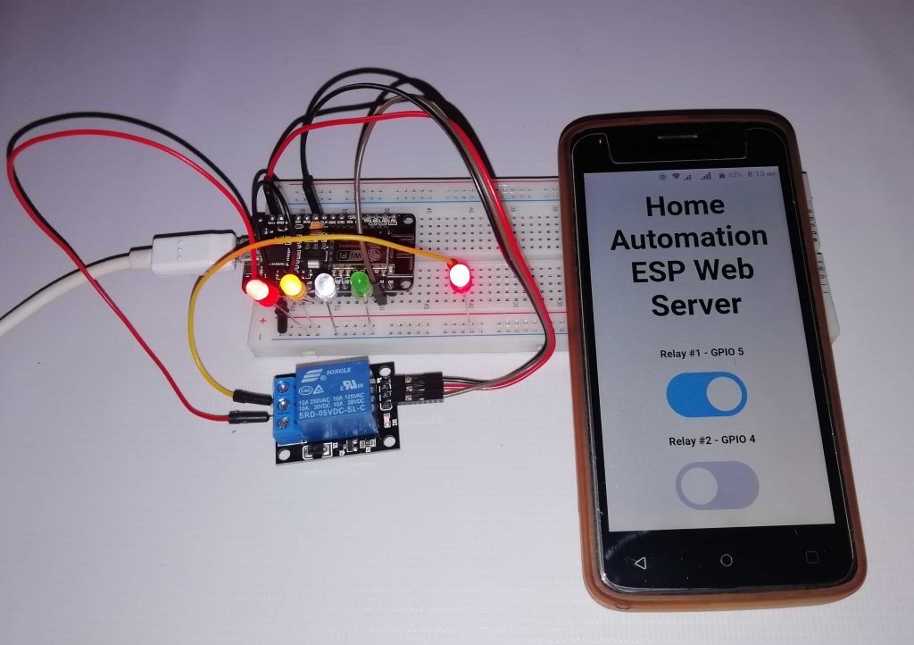
For demonstration purposes, we’re controlling 2-channels. Interface the ESP8266 NodeMCU board to the relay module as shown in the following schematic diagram.

Demonstration
- Now, after completing the coding part and made necessary changes. Its time to upload the code to your ESP8266 NodeMCU board using Arduino IDE.
- Open the Serial Monitor at a baud rate of 115200. Now, Press the ESP8266 RST button to get its IP address.
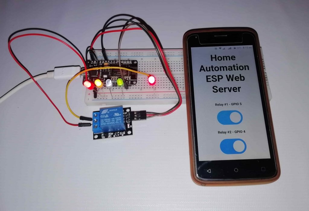
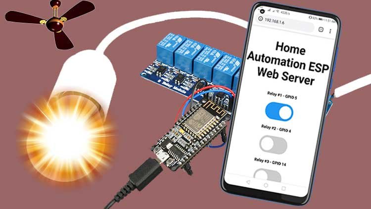
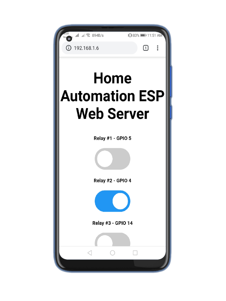
- Then, open a browser in your local network and type the ESP8266 IP address. You will now get access to the web server.
- Additionally, should get something as shown below with as many buttons as the number of relays defined in your program sketch.
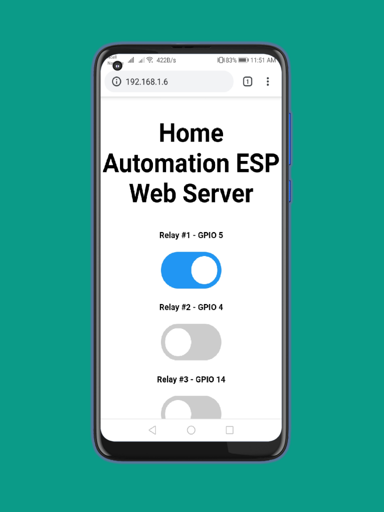
Note: Now, you can use the buttons to control your relays remotely using your smartphone, laptop, or PC in your Local Network.
For a final project, make sure you place your NodeMCU board and relay module inside a case to avoid any High voltage pins exposed.
Wrapping Up
I hope you have understood that it is a great idea to control home appliances using relays with the ESP8266. So, this was the Home Automation with ESP8266 Web Server & Relay Module Control Home Appliances from Local Network Projects. You can also read our other Guide to control RFID Module With NODEMCU.
Controlling a relay with the ESP8266 is very easy as controlling LEDs from Webserver, you just need to send HIGH and LOW signals as we do to control an LED.
I hope you love this awesome NodeMCU based smart home automation system. If you have any doubts or queries then do let me know in the comment section below.


I am trying to venture into this project. I am a retired Air Force officer having no much of software knoledge. Anyway let me see this. I might contact you in case of any hold up.