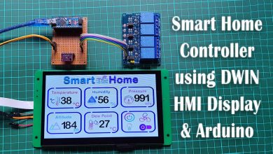
RGB LED Color Control using Arduino and Rotary Encoder
RGB LED Controller using Rotary Encoder & Arduino
Overview: RGB LED Color Controller
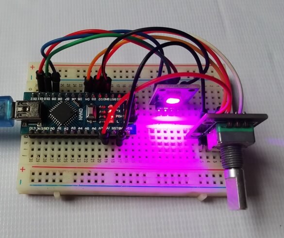
In this post, we are continuing to learn about RGB LED Color Control using Arduino and Rotary Encoder. We will rotate the Rotary Encoder to assign the value. The red, green, and blue colors will merge to display a brand new color based on that value. Here I’m using Single RGB Color LED that has Red and Green and Blue colors but you can use a long RGB LED strip as well. Besides, you can use any RGB Color LED to regulate colors using this program code.
Components Required
The following is the list of all the components required for controlling RGB LED color using a rotary encoder & Arduino. You can buy them from the Amazon links provided below:
| S.N | Components Name | Quantity | |
|---|---|---|---|
| 1 | Arduino NANO Board | 1 | https://amzn.to/3iZcNTe |
| 2 | 360 Degree Rotary Encoder | 1 | https://amzn.to/3z41MWb |
| 3 | 5MM RGB LED | 1 | https://amzn.to/2XFdLf9 |
| 4 | Male to Male Jumper Wires | 10 | https://amzn.to/3CZoG3y |
| 5 | Breadboard | 1 | https://amzn.to/3gg8KzV |
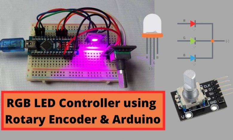
What is Rotary Encoder?
A rotary encoder is also called a shaft encoder. It is an electro-mechanical device that converts the position or motion of a shaft or axle to analog or digital output signals. There are two main kinds of rotary encoder:
- Absolute Encoder
- Incremental Encoder
The output of an absolute encoder shows the shaft position, making it an angle transducer. The output of an incremental encoder provides information about the shaft’s motion, which is usually processed elsewhere into information like position, speed, and distance.
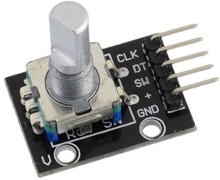
How Rotary Encoder Works?
The encoder features a disk with uniformly spaced contact areas that are attached to the common pin C and two other separate contact pins A and B, as highlighted below.
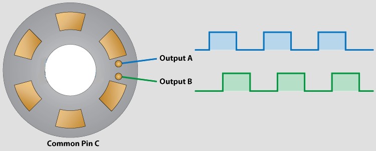
When the disk will start rotating step by step, pins A and B will start contacting the common pin and thus the two square wave output signals are going to be generated respectively.
Any of the two outputs are going to be used for determining the rotated position if we just count the pulses of the signal. However, if we would like to demonstrate the rotation direction as well, we’d like to consider both signals at identical times.
We can recognize that it displaced the 2 output signals at 90 degrees out of phase from each other. If the encoder is rotating clockwise the output, A will be prior to output B.
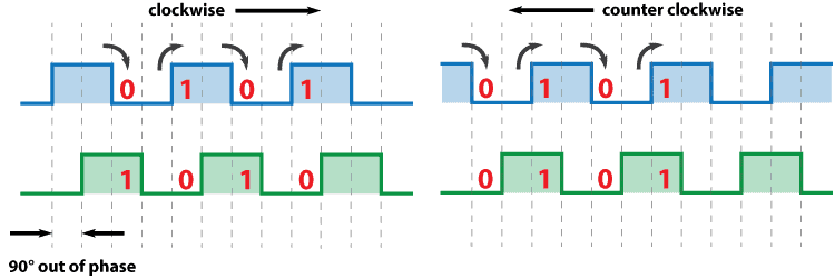
So if we count the steps every time the signal changes, from High to Low or from Low to High, we will notice at that point the two output signals have opposite values. Vice versa, if the encoder is rotating counter-clockwise, the output signals have equal values. So looking at this, we can easily program our controller to read the encoder position and the rotation direction.
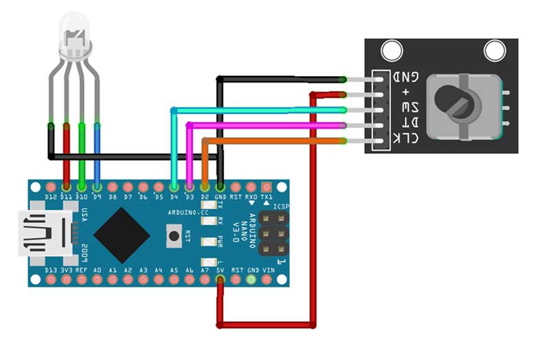
Circuit Diagram: RGB LED Color Control using Arduino & Rotary Encoder
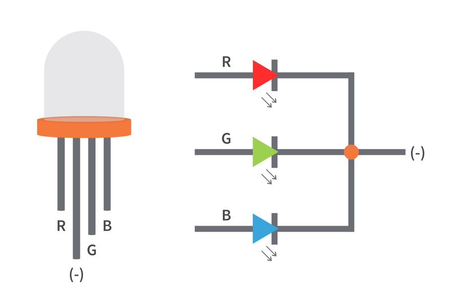
RGB LED Pinouts
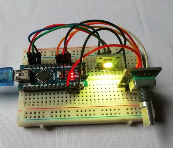
The circuit diagram below is a simple demonstration of the way to control RGB LED Color using Rotary Encoder and Arduino. You can assemble a similar circuit on a breadboard or Design and order a custom PCB from PCBWay.com
This is the PCB for the RGB LED Color Control using Arduino and Rotary Encoder.
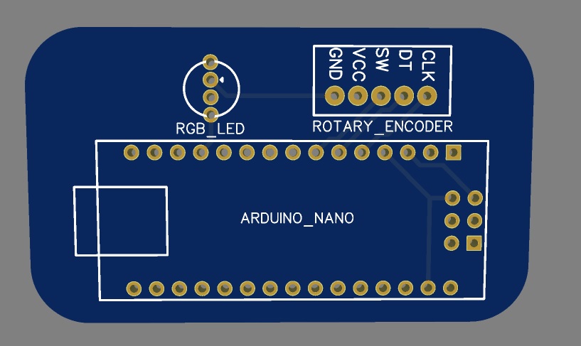
I provided the Gerber File for the PCB below. You can download the Gerber File & go for PCB ordering.
.Now you can visit the PCBWay official website by clicking here: https://www.pcbway.com/. So it will direct you to the PCBWay website.

You can now upload the Gerber File to the Website. Choose the color of your PCB, choose your quantity and place an order. You can trust PCBWay for PCB & PCBA Services because the PCB quality they provide is very good.
Source Code/Program:
The following is the final program source code for RGB LED Controller that has 8 different modes. To compile the code in Arduino IDE no extra library files are required. To upload the code, first select your Arduino Nano board and its COM port from the tools menu. Now click on the upload button.
//Program Source Code for RGB LED Color Controller using Arduino & Rotary Encoder

int encPin1 = 2; //Left turn of encoder to digital pin 2
int encPin2 = 3; //Right turn of encoder to digital pin 3
int SencPin = 4; //Push Encoder switch to digital pin 4
int ledPin = 13; // onboard LED for validation
int redPin = 9; // Red LED, connected to digital pin 9
int grnPin = 10; // Green LED, connected to digital pin 10
int bluPin = 11; // Blue LED, connected to digital pin 11
// Define Variables
int stateNum = 0; // current State number
int buttonState = 0; // current state of the button
int lastButtonState = 0; // previous state of the button
int redVal = 0; // Variables to store the values to send to the pins
int grnVal = 0;
int bluVal = 0;
int RGBVal = 0; //Value for RGB Blend
static boolean moving = false;
volatile int encVal = 0;
unsigned int lastEncVal = 1;
boolean enc1 = false;
boolean enc2 = false;

void setup()
{
//Define Inputs
pinMode(ledPin, OUTPUT);
pinMode(redPin, OUTPUT);
pinMode(grnPin, OUTPUT);
pinMode(bluPin, OUTPUT);
pinMode(encPin1, INPUT);
pinMode(encPin2, INPUT);
pinMode(SencPin, INPUT);
//Turn on resistors for encoder/switch
digitalWrite(encPin1, HIGH);
digitalWrite(encPin2, HIGH);
digitalWrite(SencPin, HIGH);
Serial.begin(9600); //Start Logging
//encoder interrupts
attachInterrupt(0, intrEncChange1, CHANGE);
attachInterrupt(1, intrEncChange2, CHANGE);
}

void intrEncChange1() //Read on interrupt Right turn - Fast +4
{
if(moving)
delay(1);
if(digitalRead(encPin1) == enc1)
return;
enc1 = !enc1;
if(enc1 && !enc2)
encVal += 4;
moving = false;
}

void intrEncChange2() //Read on interrupt Left turn - Slow -2
{
if(moving)
delay(1);
if(digitalRead(encPin2) == enc2)
return;
enc2 = !enc2;
if(enc2 && !enc1)
encVal -= 2;
moving = false;
}

void loop()
{
{
buttonState = digitalRead(SencPin); //Read Button state
if (buttonState != lastButtonState) //Compare to last state
{
if (buttonState == HIGH) //If button is pushed, incriment stateNum and blink onboard LED
{
stateNum++;
if (stateNum > 8) stateNum = 0; //Defines and loops Number of possible states
Serial.println("on");
Serial.print("State Number: ");
Serial.println(stateNum);
digitalWrite(ledPin, HIGH);
}
else
{
Serial.println("off");
digitalWrite(ledPin, LOW);
}

lastButtonState = buttonState;
} //update button state to loop
//delay(20); //Delay to avoid bounce
}
if (encVal > 255) encVal = 0; //Loop Values
if (encVal < 0) encVal = 255;
if (encVal != lastEncVal) //Compare to previous pot value
{
lastEncVal = encVal; //Update encVal to reflect new value
Serial.print("Encoder Value: ");
Serial.println(encVal);
digitalWrite(ledPin, HIGH); //Blink onboard LED
}
else
{
digitalWrite(ledPin, LOW);
//delay(100); //Delay to avoid bounce
}

//Begin States section

if (stateNum == 0) //All LEDs make white, off to brightest
{
Serial.println("0 White");
grnVal = 255 - encVal; //Common Anode LED means inverse values
bluVal = 255 - encVal;
redVal = 255 - encVal;
}
else if (stateNum == 1) //Blend Green to Blue
{
Serial.println("1 Green to Blue");
grnVal = encVal;
bluVal = 255 - encVal;
redVal = 255;
}
else if (stateNum == 2) //Blend Blue to Red
{
Serial.println("2 Blue to Red");
bluVal = encVal;
redVal = 255 - encVal;
grnVal = 255;
}
else if (stateNum == 3) //Blend Red to Green
{
Serial.println("3 Red to Green");
redVal = encVal;
grnVal = 255 - encVal;
bluVal = 255;
}
else if (stateNum == 4) //Blend RGB
{
Serial.println("4 Blend All R-G-B-R");
if (encVal < 86) // Lowest third of range (0-85)
{
RGBVal = (encVal * 3) ; // Normalize to 0-255

redVal = RGBVal; // Red from full to off
grnVal = 255 - RGBVal; // Green from off to full
bluVal = 255; // Blue off
}
else if (encVal < 171) // Middle third of range (86-170)
{
RGBVal = ( (encVal - 86) * 3); // Normalize to 0-255

redVal = 255; // Red off
grnVal = RGBVal; // Green from full to off
bluVal = 255 - RGBVal; // Blue from off to full
}
else // Upper third of range (171-255)
{
RGBVal = ( (encVal - 171) * 3); // Normalize to 0-255

redVal = 255 - RGBVal; // Red from off to full
grnVal = 255; // Green off
bluVal = RGBVal; // Blue from full to off
}
}
else if (stateNum == 5) //Red Dim
{
Serial.println("5 Red Dim");
redVal = 255 - encVal;
grnVal = 255;
bluVal = 255;
}
else if (stateNum == 6) //Green Dim
{
Serial.println("6 Green Dim");
redVal = 255;
grnVal = 255 - encVal;
bluVal = 255;
}
else if (stateNum == 7) //Blue Dim
{
Serial.println("7 Blue Dim");
redVal = 255;
grnVal = 255;
bluVal = 255 - encVal;
}
else if (stateNum == 8) //Purple Dim
{
Serial.println("8 Purple Dim");
redVal = 255 - encVal;
grnVal = 255;
bluVal = 255 - encVal;
}

//Send results to LEDs
analogWrite(redPin, redVal);
analogWrite(grnPin, grnVal);
analogWrite(bluPin, bluVal);
}
After successful upload of the program. open the serial monitor at the baud rate of 9600. You can see live data over there while rotating the encoder. There are 8 different modes for controlling your RGB LED color.
Video Tutorial
Conclusion
That’s all about RGB LED Color Control using Arduino and Rotary Encoder. So friends I hope you like this short and simple tutorial. Please share it with your friends. If you face any problems with this project feel free to comment down below.