Fingerprint Door Lock System using Arduino and Smartphone
Biometric Door Lock using Arduino
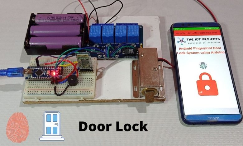
Overview: Arduino Fingerprint Door Lock
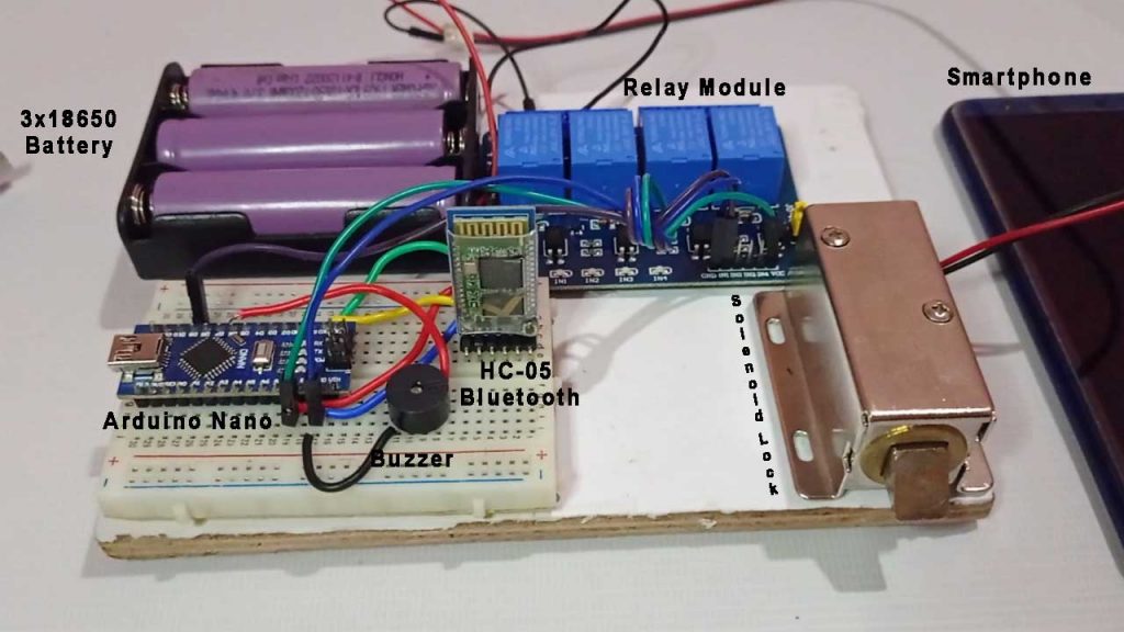
In this project, we are going to build a Fingerprint Door Lock using Arduino Nano with Bluetooth Module, Solenoid Lock, and Android SmartPhone. An Android application is designed, which scans and verifies the fingerprint and sends confirmation data to Arduino through Bluetooth serial communication. This system uses a built-in smartphone Fingerprint sensor to lock and unlock the door.
Nowadays, Electronically controlled door locks are popular. Traditional key-based mechanical door locks are slowly going out of the trend. People of today’s world need easy access to control their home appliances and add more security to your home. The IoT trend is gradually increasing, we can see different types of IoT-based smart door locks, RFID-based Master card door locks, and Password-based security door locks, etc.
Components Required
The Components required for Fingerprint Door Lock System using Arduino and Smartphone projects are as follows:
| S.N | Components Name | Quantity | |
|---|---|---|---|
| 1 | Arduino Nano | 1 | https://amzn.to/3hNy9B0 |
| 2 | HC-05 Bluetooth Module | 1 | https://amzn.to/3wnuzCX |
| 3 | Solenoid Lock | 1 | https://amzn.to/3hq3eMo |
| 4 | Single Channel Relay Module | 1 | https://amzn.to/3hoge4X |
| 5 | 3x18650 battery holder | 1 | https://amzn.to/3jSe7rE |
| 6 | 3.7V 18650 Rechargeable Battery | 3 | https://amzn.to/3jTLv1t |
| 7 | Buzzer | 1 | https://amzn.to/2OKdkvv |
| 8 | Jumper Wires | 10 | https://amzn.to/2JWSR44 |
| 9 | Breadboard | 1 | https://amzn.to/2NP2UKL |
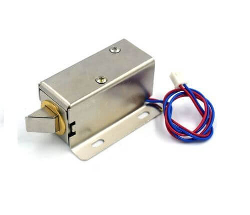
Solenoid Lock
In traditional door locks, there is a key to pull or push the latch, and we have to operate it manually. But on a solenoid lock, the latch can be operated automatically by applying some voltage. The solenoid lock contains a low-voltage solenoid that pulls the latch back to the door while an interrupt is activated (e.g. pushbutton, relay, etc.). The latch maintains its position until the interrupt is active. The operating voltage for the solenoid lock is 12V. You can also use 9V, but this results in slower operation. Solenoid door locks are mainly used to automate operations in remote areas without involving any human effort.
Circuit Diagram: Arduino Fingerprint Door Lock
The circuit diagram for Fingerprint Door Lock System using Arduino and Smartphone is given below:
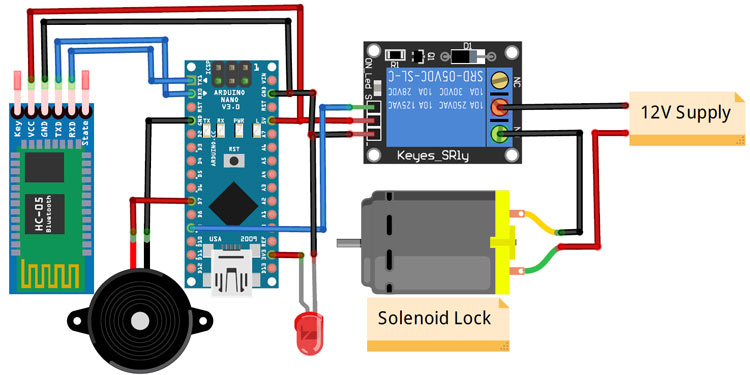
Circuit assembly for this project is very simple. Here we are only connecting a Bluetooth Module, a relay module, and a buzzer with Arduino Nano. The VCC and GND pins of the Bluetooth module are connected to 5V and GND of Nano while Tx and Rx pins are connected to Rx and Tx of Arduino Nano respectively. Similarly, the input pin of the relay is connected to the Digital pin 9 of Arduino Nano while VCC and Ground pins are connected to the 5V and GND pin of Arduino Nano. The positive pin of the buzzer is connected to Digital pin 7 of Arduino and the negative pin is connected to the GND of Arduino Nano.
PCB Designing & Ordering
You can simply assemble the circuit on a breadboard. But if you don’t want to assemble the circuit on a breadboard, you can follow this schematic and build your own PCB. You can download the Gerber file of my PCB Design from the link attached below. The PCB looks like the image shown below.

I have provided the Gerber File for Fingerprint Door Lock System using Arduino and Smartphone PCB below.
You can simply download the Gerber File and order your custom PCB from PCBWay.
Visit the PCBWay official website by clicking here: https://www.pcbway.com/. Simply upload your Gerber File to the Website and place an order. The reason behind most of the people trusting PCBWAY for PCB & PCBA Services is because of their quality. The PCB quality is superb and has a very high finish, as expected.
Also Read: RFID Based Solenoid Door lock using Arduino
Arduino Program Code Explanation
The complete code for Fingerprint Door Lock System using Arduino and Smartphone is given at the end of this program code explanation. The stepwise explanation of the code is given below.
The program code of Arduino Fingerprint Door Lock is very simple. Because the Arduino Nano and Bluetooth module communicate via serial communication. Since we are using Arduino’s hardware serial pins (Rx & Tx). So, we don’t need to include a library for Serial Communication.
The basic function of this code is to monitor the incoming serial data. Then compare it with pre-defined conditions, if the fingerprint is authorized, unlock the lock else keep it locked.
int value1;
#define relay 9
const int buzzer = 7;
So start the code by declaring a variable to hold the data received from the Bluetooth. Also, define the Arduino pins to which the Relay and buzzer are connected.
void setup()
{
    Serial.begin(9600);
    pinMode(relay, OUTPUT);
    pinMode(buzzer, OUTPUT);
    digitalWrite(relay, HIGH);
}
Inside the setup() function, start the serial communication with a baud rate of 9600 and also set the pinMode for the Relay and buzzer pins.
void loop()
{
  Serial.print("Reading");
  while(Serial.available()==0);
  value1 = Serial.read();
  Serial.print(value1);
  if (value1==1)
  {
    Serial.print("Unlocking");
    digitalWrite(relay, LOW);
    digitalWrite(buzzer, HIGH);
    delay(500);
    digitalWrite(buzzer, LOW);
    delay(3000);
    digitalWrite(relay, HIGH);
  }
  if (value1==0)
  {
      digitalWrite(relay, HIGH);
      digitalWrite(buzzer, HIGH);
      delay(2000);
      digitalWrite(buzzer, LOW);
      Serial.print("Locking");
  }
}
Similarly, inside the loop() function, check for the availability of data from the Bluetooth module, if data is available, then read the data and store it in a variable. After that, use an if statement to compare it and see if it is a 1 or 0. If the data is 1, then open the lock, else keep it locked.
Final Program Code: Fingerprint Door Lock System using Arduino and Smartphone
int value1;
#define relay 9
const int buzzer = 7;
void setup()
{
    Serial.begin(9600);
    pinMode(relay, OUTPUT);
    pinMode(buzzer, OUTPUT);
    digitalWrite(relay, HIGH);
}
void loop()
{
  Serial.print("Reading");
  while(Serial.available()==0);
  value1 = Serial.read();
  Serial.print(value1);
  if (value1==1)
  {
    Serial.print("Unlocking");
    digitalWrite(relay, LOW);
    digitalWrite(buzzer, HIGH);
    delay(500);
    digitalWrite(buzzer, LOW);
    delay(3000);
    digitalWrite(relay, HIGH);
  }
  if (value1==0)
  {
      digitalWrite(relay, HIGH);
      digitalWrite(buzzer, HIGH);
      delay(2000);
      digitalWrite(buzzer, LOW);
      Serial.print("Locking");
  }
}
After connecting the circuit diagram connect the Arduino to the laptop and upload the code (Remove the TX & RX pins, before uploading the code, Select your correct board and its COM port from the tools menu).
Android App for Arduino based Fingerprint Door Lock
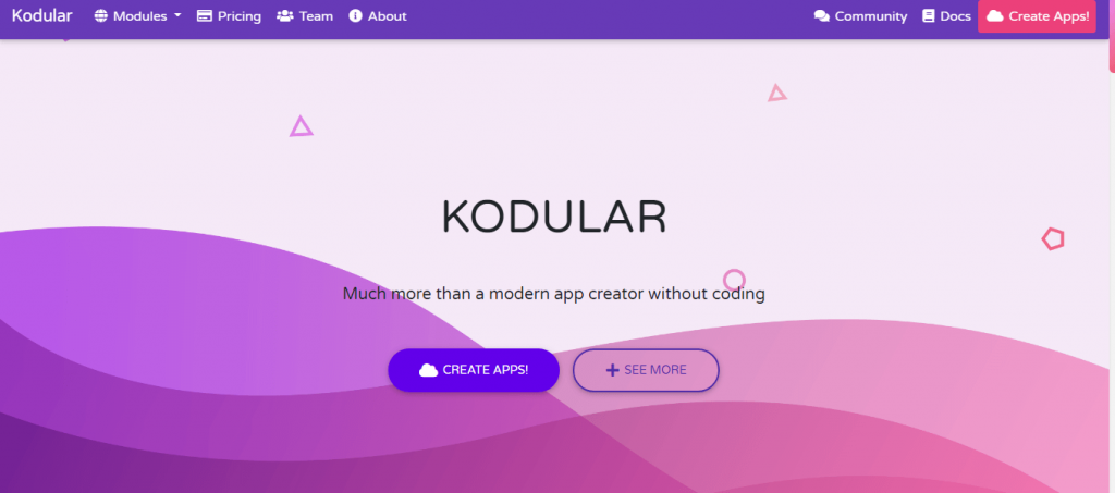
The app for this project was designed using the Kodular app inventor. Creating an app using Kodular is very simple. you can make an app by combining the blocks according to the flow chart of your project. To create an app with Kodular, navigate to Kodular.io and create an account and then click on the ‘Create Apps’ option.
Testing the Fingerprint Door Lock using Arduino Project
After downloading and installing the .apk and connecting the hardware as per the circuit diagram. Turn on the Bluetooth of your smartphone and then pair the HC05 Bluetooth module with your phone.
Now open the app and click on the Bluetooth icon, and connect with the Bluetooth module.
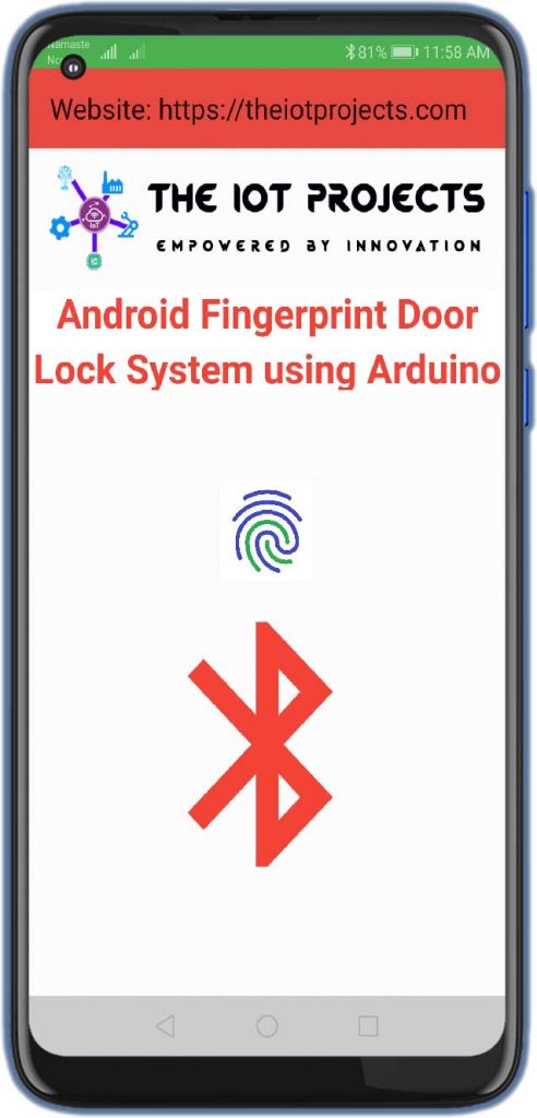
Once the Bluetooth module connects with the app, the Bluetooth icon changes into the Lock Icon.
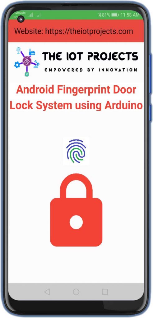
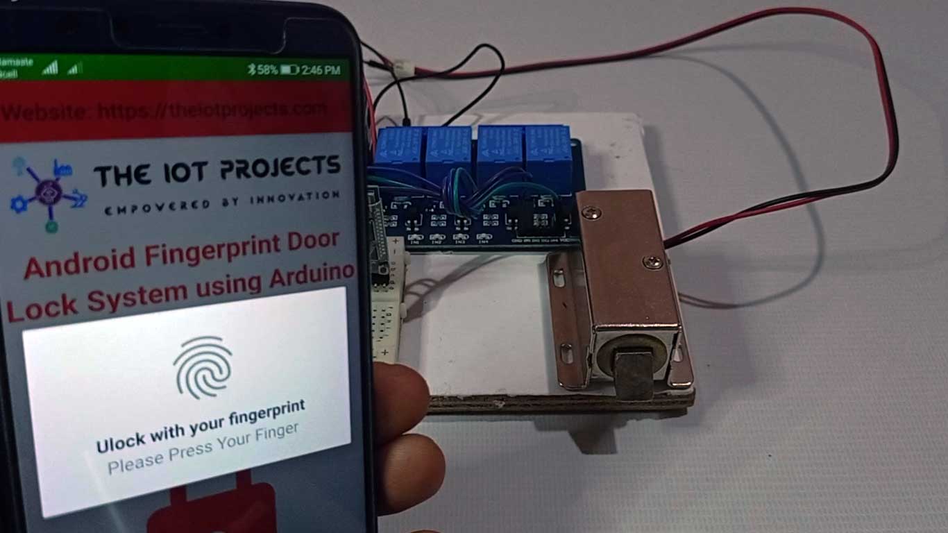
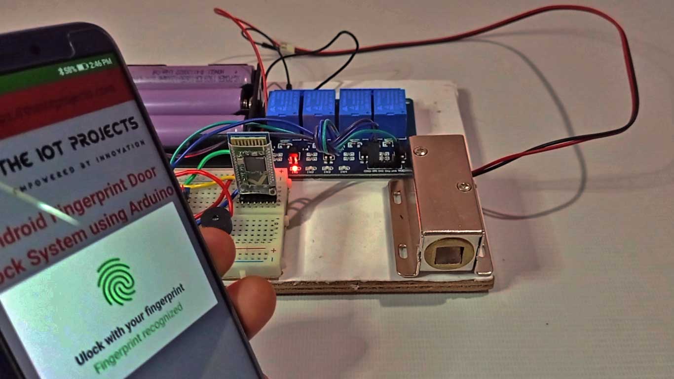
After that, touch the fingerprint button and it will ask you to scan your finger on the fingerprint sensor.
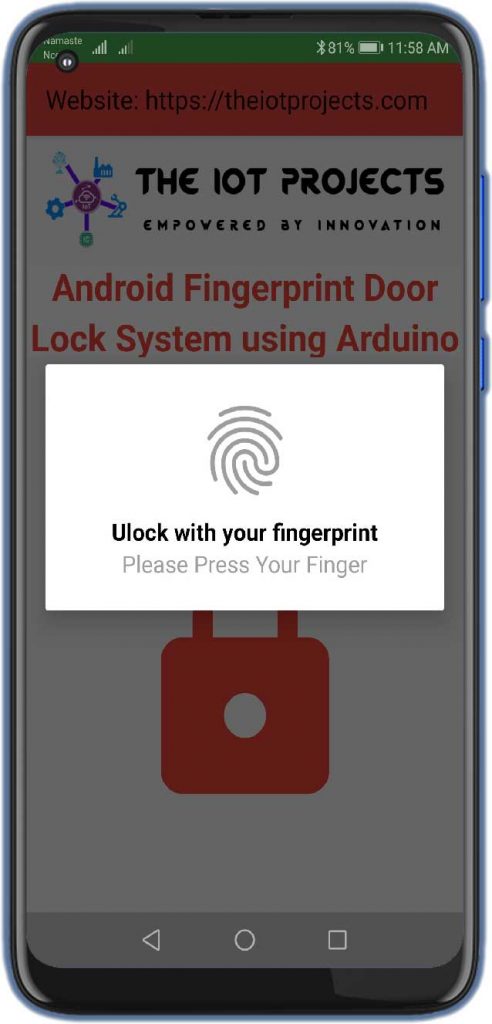
If the fingerprint is authentic, then it will open the door else the door will remain in a locked position.
This is how you can use your smartphone’s fingerprint sensor to control a solenoid door lock. A project demonstration and video tutorial is given below.
Conclusion
That’s all about Fingerprint Door Lock system using Arduino and Smartphone projects. I hope this project was helpful for you. If you have any doubts or queries, comment down below:

Fingerprint Door Lock System using Arduino and Smartphone
send full documentation of this project.
Gmail :
pavankumar190602@gmail.com.
I NEED FULL TUTORIAL PLIS, THANKS