Bidirectional Visitor Counter & Automatic Light Control using Arduino
Arduino Automatic Room Light Controller using Bidirectional Visitor Counter
Introduction
This project will help you to create a Bidirectional visitor counter and automatic light control system using an Arduino. This project is based on a pair of IR (infrared) sensors that detect an obstruction when there is an interrupt. Actually, the system can detect visitors from both directions. Basically, the number of visitors entering and also the number of visitors leaving.
This Arduino based Bidirectional Visitor Counter can calculate the number of individuals entering the project room, shopping center, office, entrance works. we can also use it at the gates of parking areas and other public places. The device calculates the total number of individuals entering through the gate and also the total number of individuals leaving through the same gate. At the same time, it calculates the total number of individuals currently in the room. When nobody is in the room, the total number of people is 0 (zero), then the light in the room is automatically turned “OFF“. When a single person is found inside the room, the lights again turn “ON“. We automated the lighting control system based on the presence of visitors.
Components Required
We can build the whole project using a single Arduino Nano board. Basically, we can use a 16×2 LCD to show the number of visitors. But to make it more compact I used a 0.96 ″ I2C OLED display. I have also integrated a 5V single channel relay to turn on light automatically when an individual is detected inside a room. The following is a list of the components you need to make a Bidirectional Visitor Counter & Automatic Light Control using Arduino. You can buy all the components online from Amazon.
| S.N | Components Name | Description | Quantity | |
|---|---|---|---|---|
| 1 | Arduino Nano | Arduino Nano R3 | 1 | https://amzn.to/3swvBuO |
| 2 | IR Sensor | IR Infrared Sensor Module | 2 | https://amzn.to/3dYWK5f |
| 3 | OLED Display | 0.96" I2C OLED Display | 1 | https://amzn.to/32WRubSv |
| 4 | Relay Module | 5V 1 Channel Relay Module | 1 | https://amzn.to/3gJNJyJ |
| 5 | Jumper Wires | Jumper Cables breadboard friendly | 20 | https://amzn.to/3vw9ZAt |
| 6 | Breadboard | Mini Breadboard | 1 | https://amzn.to/2NP2UKL |
IR Sensor for Visitor Counter
The key element of this project is the IR sensor, which acts as a human detector. When the IR sensor detects an obstruction, it calculates the individual and adds to the previous value. you can inspect some of our previous projects using IR sensors like IoT based Contactless Smart Doorbell Using IR Sensor & Blynk
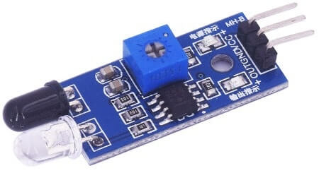
IR sensor module
The Infrared sensor module has excellent adaptability to ambient light. The sensor has an infrared transmitter and receiver. The infrared emitting tube emits a certain frequency that is reflected in the signal when faced with an obstacle. The receiver tube then received the reflected signal. Besides the IR transmitter and receiver, the circuit also has an Operational Amplifier, a variable resistor (trimmer pot), and an output LED.
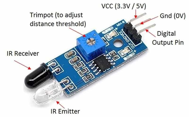
The (Infrared) IR sensor contains the following components.
1. IR LED transmitter
IR LEDs emit light, with an infrared frequency wavelength between 700nm – 1mm. It has an almost light-emission angle of 20-60 degrees and has a range of 5-10 centimeters. IR LED is white or transparent in color, so it can emit a maximum amount of light.
2. Photodiode receiver
The photodiode acts as an IR receiver as its communication when light is released. it looks like a photodiode LED, with a black coating on the outside. Blacklight absorbs maximum light.
3. LM358 Opamp
The LM358 is an operational amplifier (Op-Amp) used as a voltage comparator in IR sensors. The comparator circuit compares the threshold voltage set using the series resistor voltage of the prest and photodiode. When the series resistor voltage of the photodiode is higher than the drop threshold voltage, the Op-Amp output is higher. Similarly, when the series resistor voltage of the photodiode is less than the drop threshold voltage, the Op-Amp output is lower.
When the Op-Amp output is high, the LED turns ON at the output terminal. It represents an object, or an obstacle detected.
4. Variable Resistor
Here the variable resistor is preset. It is used to calibrate the object distance to be detected.
Circuit Diagram: Arduino Bidirectional Visitor Counter
Assembling the hardware part of the project is very simple. We just need to connect a pair of IR sensors, an OLED display, and a 5V relay module to the Arduino. The circuit diagram is given below.
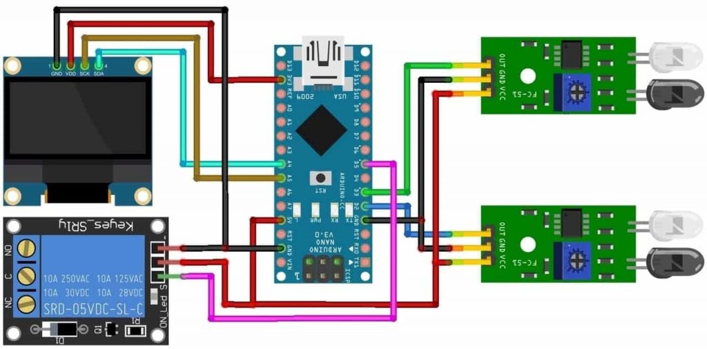
You can assemble the above circuit on the breadboard. Connect the I2C pin of the OLED display, i.e. the SDA and SCL to the Arduino A4 and A5, respectively. We require a 3.3V VCC for the OLED display. Also, connect a pair of IR sensors to the Arduino Digital Pin 2 and 3 respectively. Now, power the IR sensor either through 3..3V or by 5V. To control the relay using Arduino connect its input pin to digital pin 5. Also, provide a 5V power supply to the relay.
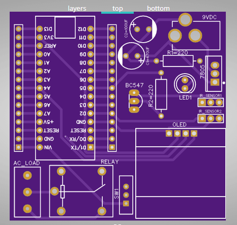
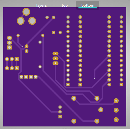
Schematic and PCB designing
If you do not want to assemble the circuit on a breadboard, I have designed a custom PCB for you. The Gerber file for a Bidirectional Visitor Counter & Automatic Light Control using Arduino PCB is given below. you can just download the Gerber file and order the PCBs from PCBWay.com.
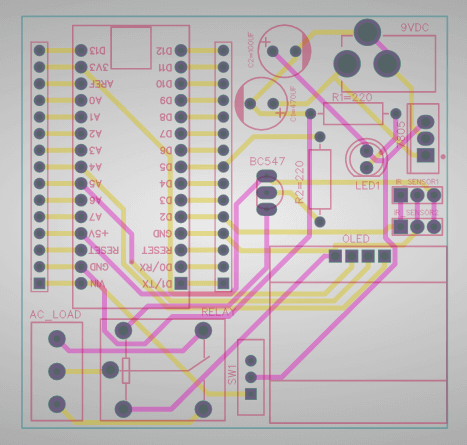
Download the Visitor Counter PCB Gerber File
Actually, you can now visit the PCBWay official website by clicking here: https://www.pcbway.com/. you’ll then be directed to the PCBWay website.
Now you can upload the Gerber file to the website and place an order. The PCB quality is superb. That’s why most people trust PCBWay for PCB and PCBA services.
We have more projects for you
- Interface LDR Photo Resistor to Arduino and Control LEDs
- IoT based Fire Detector & Automatic Extinguisher using NodeMCU
- Home Automation with ESP8266 Web Server & Relay Module Control Appliances from Local Network
Program Source Code: Bidirectional Visitor Counter
I have provided the source code for the Bidirectional Visitor Counter & Automatic Light Control using the Arduino system below. We require the code for SSD1306 and GFX OLED library collections. First, download the subsequent libraries and add them to the Arduino IDE.
Now you can copy the code and upload it to the Arduino board by selecting correct board and it’s COM Port.
#include <Wire.h>
#include <Adafruit_GFX.h>
#include <Adafruit_SSD1306.h>

#define SCREEN_WIDTH 128    // OLED display width, in pixels
#define SCREEN_HEIGHT 64    // OLED display height, in pixels
#define OLED_RESET -1       // Reset pin # (or -1 if sharing Arduino reset pin)
Adafruit_SSD1306 display(SCREEN_WIDTH, SCREEN_HEIGHT, &Wire, OLED_RESET);

#define inSensor 2
#define outSensor 3

int inStatus;
int outStatus;

int countin = 0;
int countout = 0;

int in;
int out;
int now;

#define relay 5

void setup()
{
  display.begin(SSD1306_SWITCHCAPVCC, 0x3C); //initialize with the I2C addr 0x3C (128x64)
  delay(2000);
  pinMode(inSensor, INPUT);
  pinMode(outSensor, INPUT);
  pinMode(relay, OUTPUT);
  digitalWrite(relay, HIGH);

  display.clearDisplay();
  display.setTextSize(2);
  display.setTextColor(WHITE);
  display.setCursor(20, 20);
  display.print("Visitor");
  display.setCursor(20, 40);
  display.print("Counter");
  display.display();
  delay(3000);
}

void loop()
{
  inStatus =  digitalRead(inSensor);
  outStatus = digitalRead(outSensor);
  if (inStatus == 0)
  {
    in = countin++;
  }

  if (outStatus == 0)
  {
    out = countout++;
  }

  now = in - out;

  if (now <= 0)
  {
    digitalWrite(relay, HIGH);
    display.clearDisplay();
    display.setTextSize(2);
    display.setTextColor(WHITE);
    display.setCursor(0, 15);
    display.print("No Visitor");
    display.setCursor(5, 40);
    display.print("Light Off");
    display.display();
    delay(500);
  }
  else
  {
    digitalWrite(relay, LOW);

    display.clearDisplay();
    display.setTextColor(WHITE);

    display.setTextSize(1);
    display.setCursor(15, 0);
    display.print("Current Visitor");
    display.setTextSize(2);
    display.setCursor(50, 15);
    display.print(now);

    display.setTextSize(1);
    display.setCursor(0, 40);
    display.print("IN: ");
    display.print(in);

    display.setTextSize(1);
    display.setCursor(70, 40);
    display.print("OUT: ");
    display.print(out);

    display.display();
    delay(500);
  }
}
Tests and Results
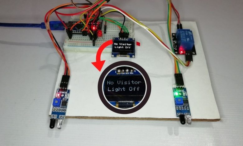
After uploading the visitor counter code to the Arduino board, the device is ready to use. The device has a pair of IR sensor modules. we should place one IR sensor at the entrance and also the other at the exit, i.e. inside the room door and outside the room door.
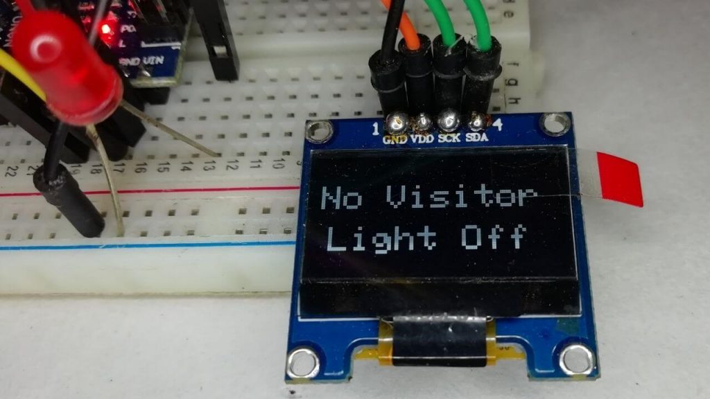
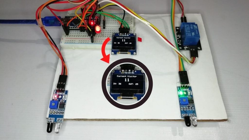
When there are no visitors within the room, the lights go off automatically, and also the OLED display shows that no visitors are within the room. When someone enters, the visitor is added, and therefore the OLED display displays the number of incoming visitors. and the light is activated automatically.
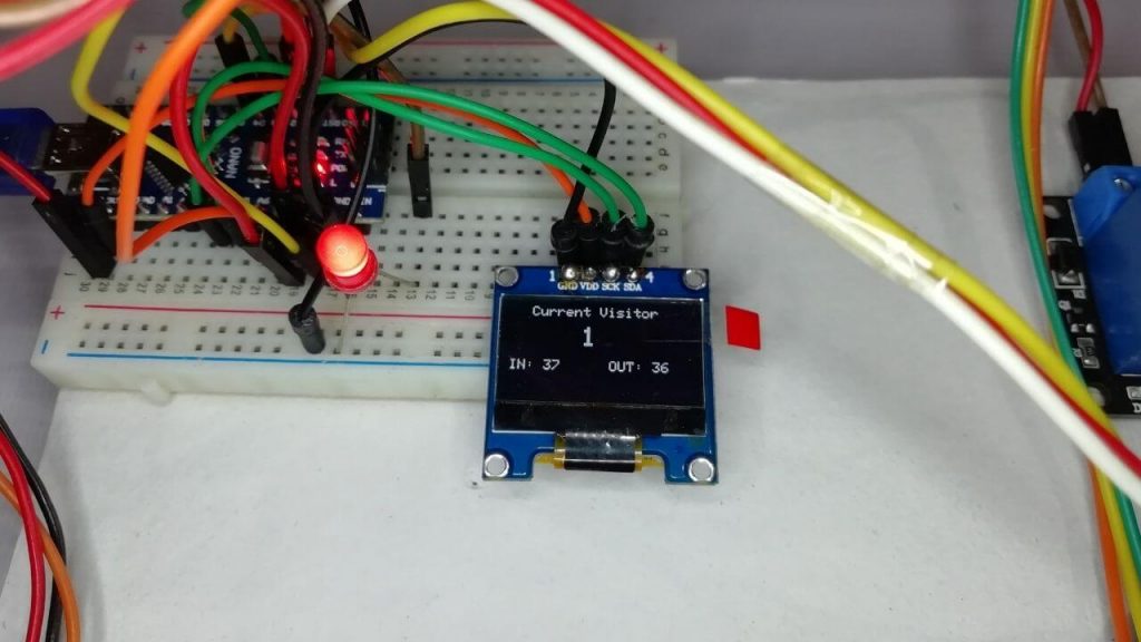
Basically, when an individual leaves the room or exits, the visitor is reduced. Thus the entire number of current visitors displayed in OLED is also reduced. The OLED display also displays the number of visitors visiting the room and also the number of visitors leaving.
This is how Bidirectional Visitor Counter works with Automatic Light Control system using Arduino. It is useful for project hall, school, office, function, etc.
Video Demonstration
Conclusion
So, that’s pretty much for this tutorial. I hope you enjoyed creating your Bidirectional Visitor Counter & Automatic Light Control using Arduino. If you did, don’t forget to share this article with your friends. Want help? let me know in the comment section below.


can i add servo motor as well,to modify the project
Yes you can