IoT based Temperature Control Fan using ESP8266 & Blynk
Temperature Controlled IoT Fan using ESP8266
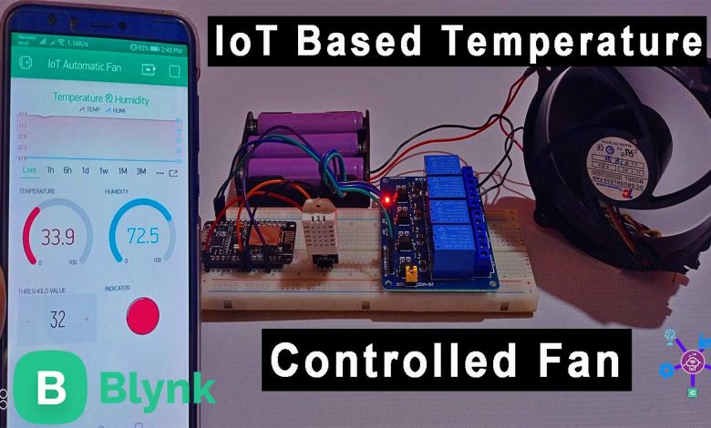
Overview: Temperature based Automatic IoT Fan
The main objective of this project is to build IoT based temperature control fan using NodeMCU ESP8266 & Blynk cloud for home automation. This device will be able to control your AC Home Appliances like AC, Fan, Heater, Cooler, or even light bulb, etc. Suppose you came from work, enter the room, and feel hot. After a while you want your cooler or fan to be “ON” automatically, and then “OFF” when the room temperature is back to normal. If you are searching for such a project, then you’re in the right place.
Nowadays, technology is advancing and houses are getting smarter. Modern houses are usually shifting from conventional switches to some kind of IoT-based centralized control system. In this project, we will use the ESP8266 NodeMCU development board, a DHT11/DHT22 Temperature, and Humidity Sensor, and a relay module to control your fan/cooler automatically based on your room temperature. We use the Blynk IoT app for monitoring the DHT11/DHT22 sensor temperature and humidity data and set temperature thresholds. When Temperature rises above the threshold temperature, the cooling fan connected to a relay will start automatically.
Working of Temperature-control Fan for Home Automation System
This temperature-based automatic fan control system comprises components like the ESP8266 board, Relay, and Temperature Sensor. The entire system depends on the Relay and DHT11/DHT22 sensor. As the temperature rises the relay will be turned “ON” and if the temperature drops below the threshold value, then Relay will be turned “OFF “. Hence, the appliances attached to the Relay will also turn ON and OFF accordingly.
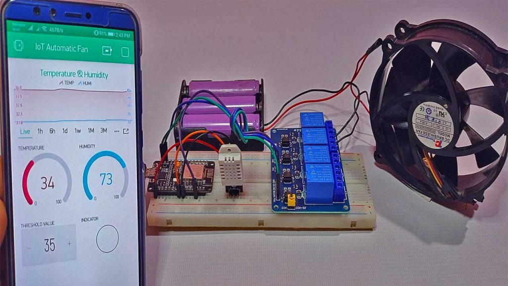
Here we have used a fan as an appliance for demonstration purposes. We can set the temperature threshold value as well as monitor the temperature and humidity of a room from the blynk app remotely. Therefore, the project hardware and smartphone both should be connected to the internet. Now, when the NodeMCU ESP8266 board receives the temperature threshold value, it compares with the DHT temperature value and starts triggering the relay accordingly.
Components Required
The components required for making an IoT-based Temperature control fan using NodeMCU and Blynk are provided below. You can go through the link to buy them from amazon.
| S.N | Components Name | Quantity | |
|---|---|---|---|
| 1 | NodeMCU ESP8266 12E Development Board | 1 | https://amzn.to/3zc4715 |
| 2 | DHT22 Temperature & Humidity Sensor | 1 | https://amzn.to/2UWUjJy |
| 3 | Single channel 5V Relay module | 1 | https://amzn.to/3hoge4X |
| 4 | 12V DC Fan | 1 | https://amzn.to/3ep4KvZ |
| 5 | 3x18650 battery holder | 1 | https://amzn.to/3jSe7rE |
| 6 | 3.7V 18650 Rechargeable Battery | 3 | https://amzn.to/3jTLv1t |
| 8 | Jumper Wires | 10 | https://amzn.to/2JWSR44 |
| 9 | Breadboard | 1 | https://amzn.to/2NP2UKL |
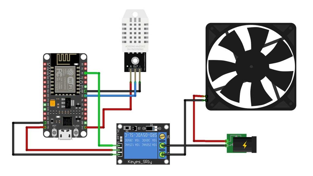
Circuit Diagram: IoT Automatic Fan Control System
The circuit diagram of IoT based Temperature Control Fan using ESP8266 & Blynk is very easy to understand. Actually, here we are controlling a Relay using ESP8266 and DHT11/DHT22 sensor for simple automation. You can easily assemble the circuit diagram following the circuit diagram and pins connection table will help you to interface all the components to the NodeMCU ESP8266.
| DHT11/DHT22 Sensor | NodeMCU ESP8266 PINS |
|---|---|
| VCC | 3.3V |
| GND | GND |
| Signal | D5 |
| 12V DC Fan | Relay output Pins |
| VCC | 12V adaptor +ve pin |
| GND | NO( Normally Open) |
| 5V Relay Module | NodeMCU Pins |
| VCC | 5V |
| GND | GND |
| Signal Pin | D2 |
PCB Designing for IoT Temperature control Fan
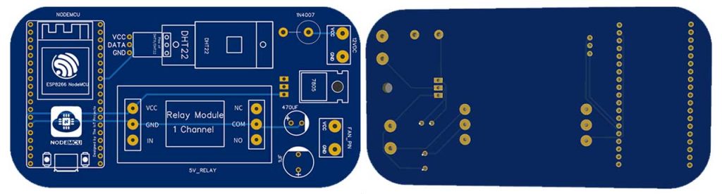
The PCB for IoT-based Temperature Control Fan using ESP8266 is designed in PCB making tool EasyEDA. Here, you can see the View of the PCB. The Gerber file for the PCB is given below. You can download the Gerber file and order the PCB online from PCBWay.
PCB Ordering & Assembly
Now you can visit https://www.PCBWay.com/ and order the PCB. It is one of the biggest PCB manufacturer companies in China. They offer very good quality PCB at a reasonable price.

Recently PCBWay started their CNC 3D Printing services. If you want to convert your project into a prototype/final product, then you can design and order CNC Machining parts online. There is a $25 SALE on custom metal & plastic parts. Grab this Custom Prototype Manufacturing Service now.
Setting up Blynk IoT Application
Now download this blink application from the play store/App store available for both Android and iOS. Sign up to the Blynk IoT cloud using your email address and password.
Now, click on the new project give your project a name. I am giving the “IoT Automatic Fan” select the NodeMCU board and then set the connection type as WiFi. Finally, click on create button.
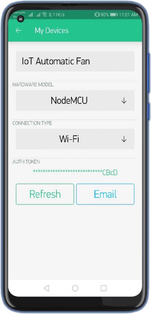
The Blynk Authentication token will be sent to your email address. We will need it later on in programming.
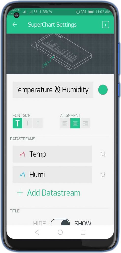
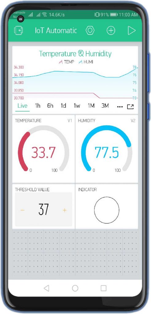
Tap on the plus (+) icon on your main screen and add the Superchart widget. Now, add two gauges then we will add Numeric Input widgets. We will also add one LED Widget for an indicator.
Click on the super chart widget and Give it a name. Also, add Temperature and Humidity Datastreams to Virtual pin V1 and V2 respectively. You can do further customization according to your need.
Now come back to the main dashboard to configure two Gauges. One will show you the Temperature values and others will show you the Humidity. For Temperature, We’ll select the virtual pin V1 and we’ll set the value from 0 to 100 you can also set the colors for this gauge.
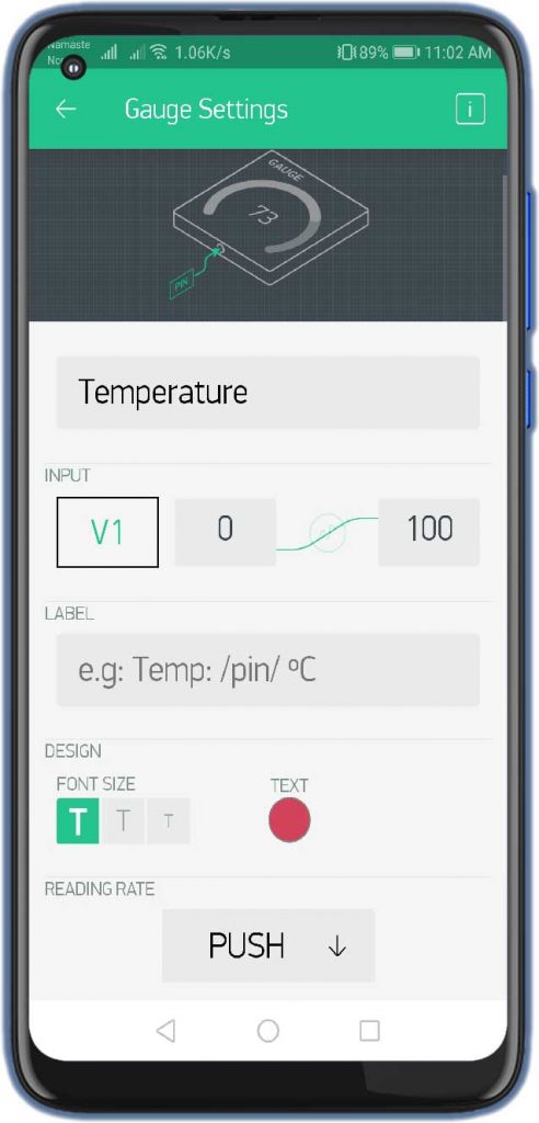
Now we’ll do for the Humidity level. we’ll select the virtual V2 pin and we’ll select the values from 0 to 100.

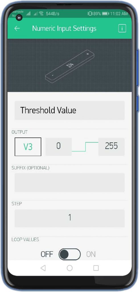
For Threshold Value, we will use virtual pin V3 and V0 pin for LED indicator respectively.
That’s it with the application setup for IoT Based temperature control fan Using ESP8266 & Blynk. Your final app looks like the below screenshot.
Source/Program Code
The Complete Arduino Code for Temperature Control Fan using ESP8266 & Blynk is provided at the end of this programming code explanation Here we have explained how the code is working.
#include <ESP8266WiFi.h>
#include <BlynkSimpleEsp8266.h>
#include "DHT.h"
#define DHTPIN D5     // Digital pin connected to the DHT sensor

// Uncomment whatever type you're using!
//#define DHTTYPE DHT11   // DHT 11
#define DHTTYPE DHT22   // DHT 22  (AM2302), AM2321
//#define DHTTYPE DHT21   // DHT 21 (AM2301)
#define FAN_PIN D2   // FAN RELAY
WidgetLED FAN(V0);
Here we have included all the required library header files. Then defined the DHT sensor pin to D5. for the demonstration I am using the DHT22 sensor. If your sensor is DHT11 Comment on the DHT22 part and uncomments DHT11 one. We also defined Relay Pin to D2. Similarly, a Widget LED pin is also defined to the virtual V0 pin according to the blynk app configuration.
char auth[] = "q_URao70sxi2Z3B6Y5H0lnzE7RWgCBcD";
char ssid[] = "The_IoT_Projects";
char pass[] = "Qwertyuiop";
Replace the blynk authentication token and WiFi network credentials with yours.
float humDHT = 0;
float tempDHT = 0;
int Val=0;
Three different variables humDHT, tempDHT, and val are defined as a float and integer type.
DHT dht(DHTPIN, DHTTYPE);
We Initialize DHT sensor.
void setup() {
  Serial.begin(115200);
  pinMode(FAN_PIN, OUTPUT);
  digitalWrite(FAN_PIN, LOW);
  Serial.println(F("DHTxx test!"));
  dht.begin();
  Blynk.begin( auth, ssid , pass );
}
In the setup part, we initialize the serial monitor, DHT sensor test, and blynk server connection.
BLYNK_WRITE(V3)
{
  Val = param.asInt();
  Serial.print(" The Threshhold value is: ");
  Serial.println(Val);
  Serial.println();

}
In this part of the code, we read the temperature threshold value from the blynk app and assigning incoming values from pin V3 to a variable. We will also print this value on a serial monitor.
void loop() {

  Blynk.run();

  // Wait a few seconds between measurements.
  delay(2000);

  // Reading temperature or humidity takes about 250 milliseconds!
  // Sensor readings may also be up to 2 seconds 'old' (its a very slow sensor)
  humDHT = dht.readHumidity();
  // Read temperature as Celsius (the default)
  tempDHT = dht.readTemperature();

  // Check if any reads failed and exit early (to try again).
  if (isnan(humDHT) || isnan(tempDHT))
  {
    Serial.println("Failed to read from DHT sensor!");
    return;
  }

  Serial.print(F("Temperature: "));
  Serial.print(tempDHT);
  Serial.print(F("°C "));
  Serial.println();
  Serial.print(F("Humidity: "));
  Serial.print(humDHT);
  Serial.print(F("%"));
  Serial.println();

  Serial.println("***********************");
  Serial.println();

  // Compare Threshold value from Blynk and DHT Temperature value.
  if (Val > tempDHT)
  {
    digitalWrite(FAN_PIN, HIGH);
    FAN.off();
}
  else {
    digitalWrite(FAN_PIN, LOW);
    FAN.on();

  }

  Blynk.virtualWrite(V1, tempDHT);
  Blynk.virtualWrite(V2, humDHT);
}
In the Loop part of this code, we check the blynk server connection then wait 2 seconds to read temperature and humidity parameters from the DHT sensor. Print those values on the serial monitor. Now, the program compares the threshold value from Blynk and DHT Temperature value and triggers the relay accordingly. Lastly, it will publish the temperature and humidity data to the blynk cloud every two seconds.
Recommend readings
- Guide for Interfacing Relay with Arduino
- IoT based Fire Detector & Automatic Extinguisher using NodeMCU
- Home Automation with ESP8266 Web Server & Relay Module Control Appliances
- Fire Security System using Arduino & Flame Sensor
- Bidirectional Visitor Counter & Automatic Light Control using Arduino
Final Program Code
#include <ESP8266WiFi.h>
#include <BlynkSimpleEsp8266.h>
#include "DHT.h"
#define DHTPIN D5     // Digital pin connected to the DHT sensor

// Uncomment whatever type you're using!
//#define DHTTYPE DHT11   // DHT 11
#define DHTTYPE DHT22   // DHT 22  (AM2302), AM2321
//#define DHTTYPE DHT21   // DHT 21 (AM2301)
#define FAN_PIN D2   // FAN RELAY
WidgetLED FAN(V0);

char auth[] = "q_URao70sxi2Z3B6Y5H0lnzE7RWgCBcD";
char ssid[] = "The_IoT_Projects";
char pass[] = "Qwertyuiop";

float humDHT = 0;
float tempDHT = 0;
int Val=0;

// Initialize DHT sensor.
DHT dht(DHTPIN, DHTTYPE);

void setup() {
  Serial.begin(115200);
  pinMode(FAN_PIN, OUTPUT);
  digitalWrite(FAN_PIN, LOW);
  Serial.println(F("DHTxx test!"));
  dht.begin();
  Blynk.begin( auth, ssid , pass );
}

BLYNK_WRITE(V3)
{
  Val = param.asInt(); // assigning incoming value from pin V3 to a variable

  Serial.print(" The Threshhold value is: ");
  Serial.println(Val);
  Serial.println();

}

void loop() {

  Blynk.run();

  // Wait a few seconds between measurements.
  delay(2000);

  // Reading temperature or humidity takes about 250 milliseconds!
  // Sensor readings may also be up to 2 seconds 'old' (its a very slow sensor)
  humDHT = dht.readHumidity();
  // Read temperature as Celsius (the default)
  tempDHT = dht.readTemperature();

  // Check if any reads failed and exit early (to try again).
  if (isnan(humDHT) || isnan(tempDHT))
  {
    Serial.println("Failed to read from DHT sensor!");
    return;
  }

  Serial.print(F("Temperature: "));
  Serial.print(tempDHT);
  Serial.print(F("°C "));
  Serial.println();
  Serial.print(F("Humidity: "));
  Serial.print(humDHT);
  Serial.print(F("%"));
  Serial.println();

  Serial.println("***********************");
  Serial.println();

  // Compare Threshold value from Blynk and DHT Temperature value.
  if (Val > tempDHT)
  {
    digitalWrite(FAN_PIN, HIGH);
    FAN.off();
}
  else {
    digitalWrite(FAN_PIN, LOW);
    FAN.on();

  }

  Blynk.virtualWrite(V1, tempDHT);
  Blynk.virtualWrite(V2, humDHT);
}
Now copy this program code and paste it on your Arduino IDE. You can make your necessary changes like WiFi SSID, Password, and Blynk Authentication token. Now Choose your NodeMCU ESP8266 12E Development board and COM Port from the tools menu. Just hit that compile button and upload the code to the ESP8266 NodeMCU. Enjoy your Modern Temperature Controlled IoT Fan using NodeMCU and Blynk platform.
Video Demonstration & Guide
Wrapping Up
Finally, I have completed the IoT based Automatic temperature control fan Project. I hope you found this project useful! Drop a comment below. Stay Happy! Stay safe.


Sir Thanks a lot for this project, it helped me lot <3
SIR, DO YOU HAVE A WRITE UP FOR THIS PROJECT (IOT BASED TEMPERATURE CONTROLLED FAN)
IF YES PLEASE SEND IT TO ME VIA THE EMAIL
Sir I am facing problem with setup with BLYNK IOT can you help in setup?
In file included from c:\Users\S1\Documents\Arduino\libraries\Blynk\src/BlynkApiArduino.h:14,
from c:\Users\S1\Documents\Arduino\libraries\Blynk\src/BlynkSimpleEsp8266.h:24,
from C:\Users\S1\AppData\Local\Temp\.arduinoIDE-unsaved2023629-12396-7qxbjt.ztjh\sketch_jul29a\sketch_jul29a.ino:2:
c:\Users\S1\Documents\Arduino\libraries\Blynk\src/Blynk/BlynkApi.h:39:6: error: #error “Please specify your BLYNK_TEMPLATE_ID and BLYNK_TEMPLATE_NAME”
39 | #error “Please specify your BLYNK_TEMPLATE_ID and BLYNK_TEMPLATE_NAME”
| ^~~~~
THIS ERROR APPER TO ME
Hii mam I want this project I will pay for that plzzz currier me on myy adress
Just saw it and it really educating me on how to use blynk and esp boards thank you very much