Overview: ESP32 WiFi Repeater
Today in this session, we are going to DIY a portable ESP32 based WiFi repeater. This device will help you to extend your existing WiFi network. In this IoT Generation, we use lots of smart home appliances which require WiFi connectivity to control them remotely. So we can set up a separate WiFi network with different SSID and Passwords for those devices. Alternately, we can also use this device to provide separate internet connectivity to the guests because unlike ESP8266 based WiFi repeater, we can achieve a bandwidth of more than 15mbps i.e 3 times more. That means we can browse the internet and stream videos without interruption.
Without doing delay lets build the cheapest and portable WiFi repeater using ESP32 development board.
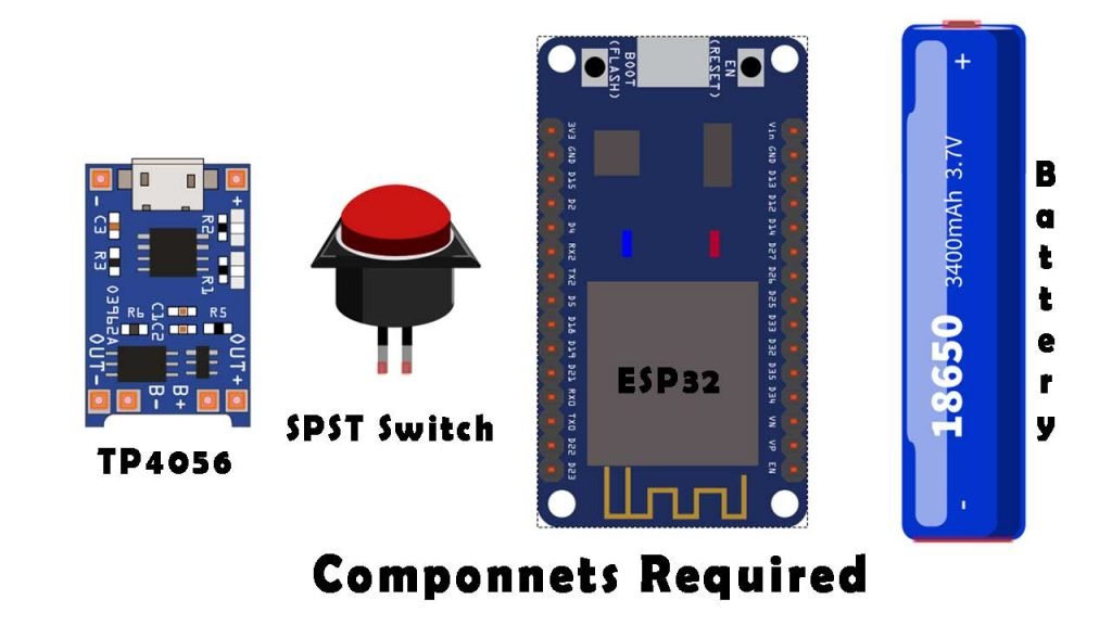
Components Required
To build ESP32 based portable WiFi repeater we require the following components. You can buy them from the amazon affiliate links provided below:
| S.N | Components Name | Quantity | |
|---|---|---|---|
| 1 | ESP32 Development Board | 1 | https://amzn.to/2SDuwFh |
| 2 | TP4056 Charging Module with protection | 1 | https://amzn.to/3aNUY5x |
| 3 | 18650 Rechargeable Battery | 2 | https://amzn.to/3f6omWU |
| 4 | Jumper cables | 5 | https://amzn.to/2JWSR44 |
| 5 | Project box | 1 | https://amzn.to/398uPNn |
| 6 | SPST Switch | 1 | https://amzn.to/315ZTZB |
Now, before diving into the project let’s learn more about ESP32 WiFi repeater.
What is ESP32 Wi-Fi Repeater & How it works?
An ESP32 Wi-Fi repeater or expander can be used to expand the coverage area of your existing Wi-Fi network. It works by receiving your existing Wi-Fi signal, amplifying it, and then transmitting the enhanced signal. With an ESP32 Wi-Fi repeater, you can effectively double the coverage area of your Wi-Fi network – to reach the far corners of your home or office, on different floors, or to expand coverage in your yard.
Basically, it is cost-effective and portable. So, lets make our own Wi-Fi repeater.
Setting up ESP32 for Flashing Wi-Fi Repeater Firmware
There is no coding or programming involved in converting this ESP32 board into a repeater but we need two things:
First, download both files from the link attached above. Simply you can download the flash download tool from the espressif website and ESP32 repeater firmware from the GitHub repository. The download might take some time depending upon your network speed.
As soon as that is done we can go to the folder where the file was downloaded. So let’s go ahead and extract both files. Okay, so we have both files extracted here.
Flash the Repeater Firmware onto the ESP32
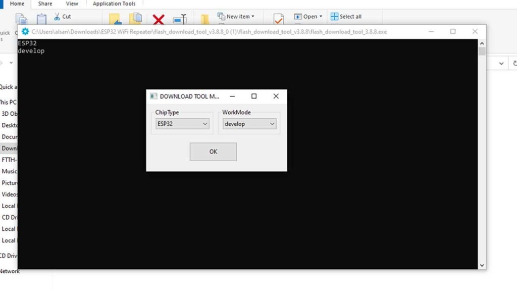
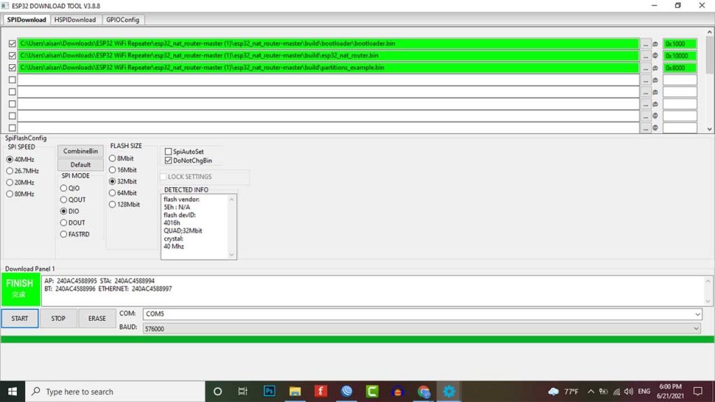
let’s run the flash download tool. so we open the folder and then we run the flash download tool as administrator. After a while, you will see a pop-up window. Here you need to click on Developer Mode and then ESP32 Download Tool. Finally, you will get the interface as below image where we add our ESP32 repeater firmware or binary files.
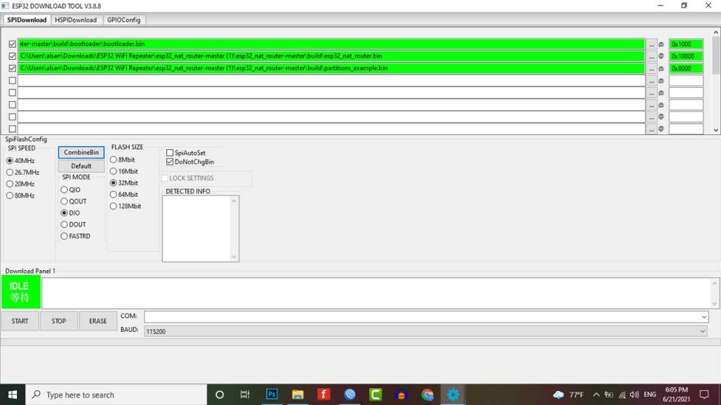
- First, we need to click on the first row and it will bring us to the download folder. So here we select the bootloader file from the ESP firmware folder. When the file is added the row turns to green.
- Similarly, we select the next row and choose the esp32 nat router file.
- Finally, on the third one, we select the partition file.
- Now, we also need to specify the hex code indicating where the files are. For the bootloader type 0x1000, for esp32 nat router file type 0x10000, and for partition file type 0x8000.
- Now tick all these three boxes and at the end as soon as you complete this also box changes to green,
Note: if yours doesn’t change to green then it means that you’ve probably done something wrong.
Well, we’ll leave the rest of these settings at their default at where they are. As you can see in the screenshot below. The SPI speed is 40MHz, SPI Mode is DIO, and flash size is 32(Mbit) Megabits.
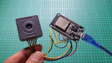
Now to upload the ESP32 WiFi repeater Firmware we have to select the COM port of our ESP32. But we’ve not connected the ESP32 module to our pc yet. So let’s go ahead and do that, we can use a standard micro USB cable.
Now after connecting our esp32 to the PC we can see and select the COM Port. We also set the baud rate to 57600.
Press and hold the boot button on your ESP32 board and click on the start button to start flashing firmware.
This time around we can see a bunch of things happening and then we can see the device MAC showing up in the same window and then the green line starts loading down then you see the finish sign on the left. This means that everything is done so now you can take your finger off the boot button and then you restart the ESP32 board by disconnecting the USB and connecting it again.
Configuring Portable WiFi Repeater using ESP32
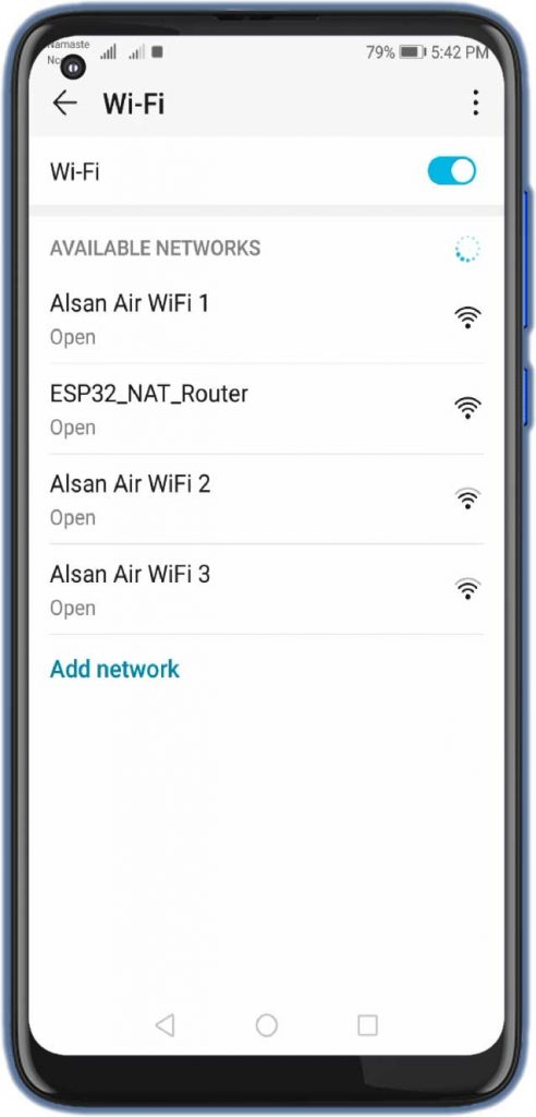
You must connect a computer to your ESP32 NAT router in order to configure it. You can do this by using a smartphone as well. After the first boot, it provides an open WiFi SSID “ESP32_NAT_Router“. Connect to this WiFi network and perform basic configuration via a simple web interface.
The web interface allows for the configuration of all the parameters required for basic forwarding functionality. Open your web browser and enter the following address: “http://192.168.4.1“. Now you should see the following page.
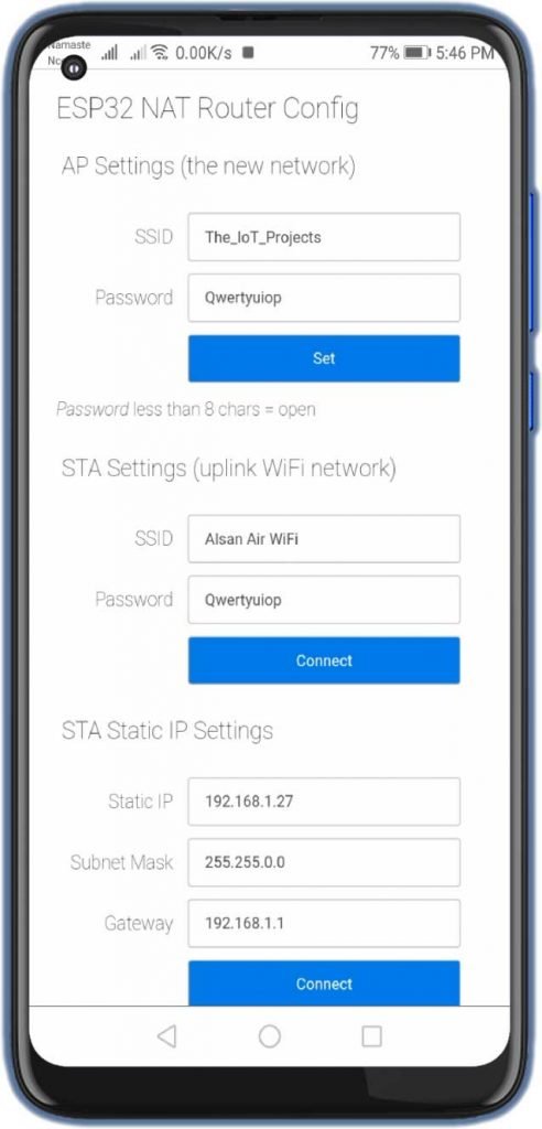
Firstly, in the “STA Settings” enter the correct WiFi credentials of your main WiFi network that you want to extend. Leave the password field for open networks. Click on “Connect“. The ESP32 reboots and will connect to your WiFi router. You should see the status LED ON after a few seconds.
You can now reload the page and change the “AP Settings“. Enter New SSID and Password and click “Set” and again the ESP reboots. Now it is ready for forwarding traffic over the newly configured Access Point.
Remember that these changes also affect the config interface, i.e. to do further configuration, enter the IP address of the newly configured Access point.
If you want to enter a ‘+’ in the web interface you have to use HTTP-style hex encoding like “The%2bIoT%2bProjects”. This will result in a string “The+IoT+Projects”. With this hex encoding, you can enter any byte value you like, except for 0 (for C-internal reasons).
Assembling and testing ESP32 Portable WiFi Repeater
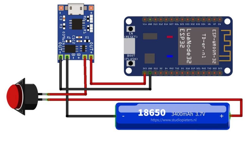
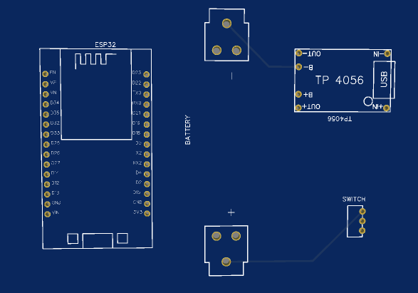
Now it’s time to assemble our portable powerful ESP32 WiFi repeater. You can use the following circuit diagram to connect each component together.
You can also order a custom PCB from PCBWay.com
Download the Gerber file and order the PCB from https://www.PCBWay.com at a cheap price.
PCBWay is quite professional in PCB manufacturing. You can try their services at extremely low prices. Only $5 for 10 PCBs and $30 in total for 20 PCBs assembly. Besides this, the new members also get a $5 sign-up bonus. That means the new users can order 10 PCBs for free.
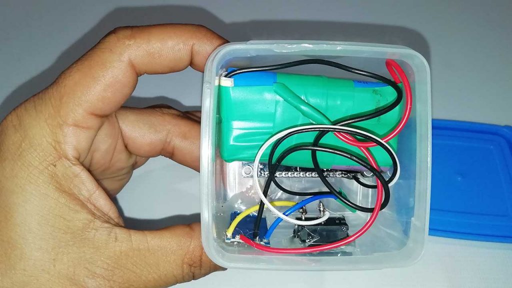
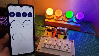
I have set up the components inside a waterproof case as shown in the images below. You can place this repeater in any corner of your home, office, or workspace.
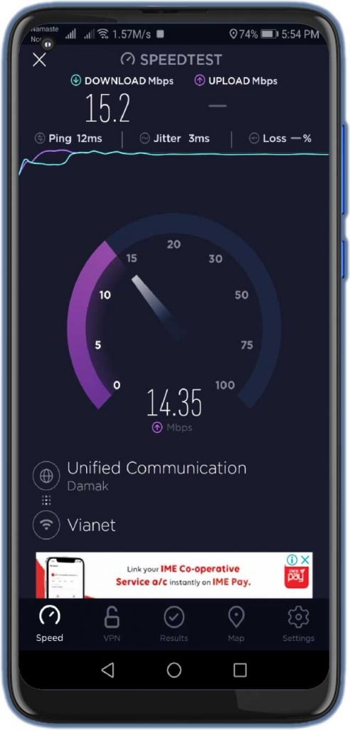
The speed test measurement show, that we can achieve about 15 Mbps in both upload and download. So streaming is also possible for a single user. Like watching Netflix, YouTube, and Browsing the Internet.
Video Demonstration
Here we have a full video tutorial for portable Wi-Fi Repeater using ESP32.
Hello Alsan,
great tutorial, that works like a charm. Just a hint. I found a improved version of the firmware with more features at https://github.com/dchristl/esp32_nat_router_extended . This seems to be better maintained than the abondened project.
Hello alsan, Can you provide the details of esp 32 board and mobile device distance from the router(when download speed 15 mbps ).
Great project Alsan. Just a bit of confusion when setting up the ESP NAT into the network, but it worked itself out and connected fine. This will be nice to extend the internet around the property. Just when I think the little ESP32 could not amaze me further, it does it again.
Can you deploy multiple repeaters to extend range ?
Yes you can, but a few settings need to be changed, example for 3 repeaters
1st : STA = mywifi (192.168.0.10) – AP Rep-1 (192.168.4.1)
2nd: STA = Rep-1 (192.168.4.2) – AP Rep-2 (192.168.5.1) set as static address
3rd STA = Rep-2 (192.168.5.2) – AP Rep-3 (192.168.6.1) set as static address
Each one needs a different AP IP and a different name
As I mentioned in a previous post, works like a champ, every time. However, I find I am NOT able to change to a different network from the one I first connected to by using the 192.168.4 webserver link. Is it necessary to flash from the start in order to switch networks. When I try to enter new credentials into the webserver, it puts the ssid and password in the url and will not work
all works but when the repeater connects to WIFI modem it says internet is not available. Please help.