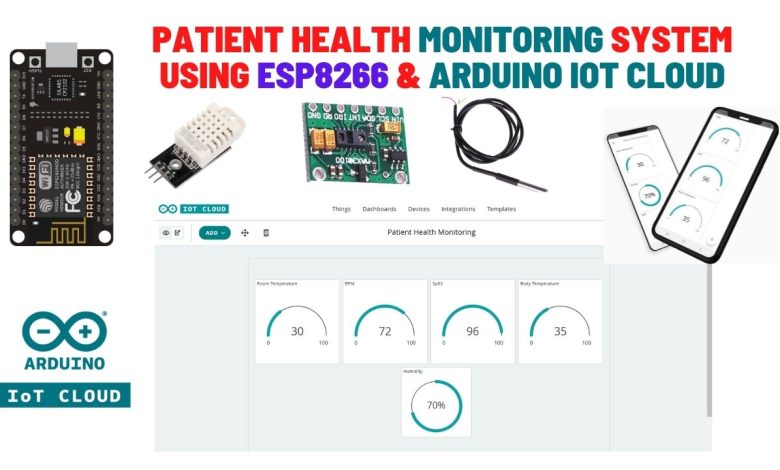
Patient Health Monitoring System using Arduino IoT Cloud with ESP8266
ESP8266 based Patient Health Monitoring System with Arduino IoT Cloud
- Overview: IoT Based Patient Health Monitoring System
- Components Required
- Circuit Diagram: Patient Health Monitoring System using Arduino IoT Cloud
- Setting Up Arduino IoT Cloud Dashboard
- Source Code/Program
- IoT_based_Patient_Health_Monitoring_System.ino
- thingproperties.h
- Secrets.h
- Testing: Patient Health Monitoring System using Arduino IoT Cloud with ESP8266
- Conclusion
In this project, we will make a Patient Health Monitoring System using Arduino IoT Cloud with ESP8266, MAX30100 Pulse Oximeter sensor, DS18B20 temperature sensor, and DHT22 Temperature & Humidity sensor. This system will monitor the parameters like room temperature, room Humidity, Heart Rate, Oxygen Saturation (Sp02) in blood, and body temperature of patients on the Arduino IoT Cloud.
Overview: IoT Based Patient Health Monitoring System
Actually, health care technology is rapidly being revolutionized with the help of the Internet of Things (IoT). Mostly elderly covid patients have high health risks. So, we need to monitor the health status of patients regularly. Therefore I decided to build an IoT-based patient health monitoring system that tracks patient health and uploads the data to the cloud server. Hence we can monitor the health parameters like body temperature, heart rate (BPM), blood oxygen levels (Sp02) as well as room temperature and humidity remotely.
In this simple device, the MAX30100 pulse oximeter sensor is used to measure Heart Rate/Pulse (BPM) and Blood Oxygen Level (SpO2). Similarly, to measure body temperature, we use the DS18B20 temperature sensor. Meanwhile, the patient is inside the room. So we need to monitor room temperature and humidity level as well. We should keep them in a room with a certain temperature and humidity level. Hence, we use the DHT22 Temperature & Humidity sensor.
Additionally, we have ESP8266 based IoT Health Care Panic Button which will alert/notifies you when your patient needs your help.
Components Required
The following are the components required for making Patient Health Monitoring System using Arduino IoT Cloud with ESP8266. All the components are easily available on amazon.
| S.N | Components Name | Description | Quantity | |
|---|---|---|---|---|
| 1 | NodeMCU | ESP8266 12E Development Board | 1 | https://amzn.to/3mTuL95 |
| 2 | DS18B20 Sensor | DS18B20 One-Wire Waterproof Temperature Sensor | 1 | https://amzn.to/3k5BCfB |
| 3 | DHT22 Sensor | DHT22 Digital Humidity Temperature Sensor | 1 | https://amzn.to/3fPl2hU |
| 4 | Pulse Oximeter Sensor | MAX30100 I2C Pulse Oximeter Sensor | 1 | https://amzn.to/3sjdrNc |
| 5 | Jumper Wires | Male to Male Jumper Wires | 8 | https://amzn.to/2JWSR44 |
| 6 | Breadboard | Solderless Breadboard MIni | 1 | https://amzn.to/3n33uRT |
MAX30100 Pulse Oximeter Sensor
MAX30100 is an integrated Pulse Oximetry and Heart Rate monitor sensor solution. It requires a 1.8V to 3.3V power supply to operate. Also, we can power it down through program code by decreasing its standby current and providing a power supply all the time. This oximeter sensor has two LEDs, photodetector optimized optics, and low-noise-analog signal processing to detect heart-rate signals.

How does MAX30100 Pulse Oximeter work?
The MAX30100 Pulse Oximeter has two built-in LEDs, in which one emits red light and the other emits infrared light. To measure pulse rate, only infrared light is required. But, both red light and infrared light are used to measure oxygen saturation (Sp02) levels in the blood. When the heart pumps the blood, there is more oxygenated blood and when the heart rests, the amount of oxygenated blood also gets decreased. Hence, by knowing the time between the rise and fall of oxygenated blood, we determine the pulse rate.
What is the major function of MAX30100 Pulse Oximeter?
Its major function is to read the absorption levels for both red light and infrared light sources and store them in a buffer. Which can be read through I2C communication. Oxygenated blood absorbs more infrared light. So, it passes more red light. But, deoxygenated blood absorbs red light and passes more infrared light.
DS18B20 Temperature Sensor
This is a pre-wired and waterproof version of the DS18B20 sensor. This sensor is useful for measuring temperature from -55°C to 125°C (-67°F to +257°F) even in wet conditions. It has a long wire, so it’s useful when a patient is a little far. Actually, the cable of this sensor is jacketed in PVC.

DS18B20 is a digital sensor, so there is no signal degradation in long distances. It is fairly precise, i.e. ±0.5°C over much of the range. This sensor works great with any microcontroller using a single digital pin.
The downside is it uses the Dallas 1-Wire protocol, which is complex and requires a bunch of code to communicate.
DHT22 Temperature & Humidity Sensor
The DHT22 is a simple, ultra-low-cost digital temperature & humidity sensor. DHT22 uses a capacitive humidity sensor and a thermistor to measure the surrounding temperature and humidity. It sends data in digital signal form so no analog input pin is required.

This DHT22 Sensor provides more precise data than DHT11 Sensor.
Alternatively, we can use the DHT11 Sensor. Learn more about DHT11 Humidity/Temperature Sensor.
Circuit Diagram: Patient Health Monitoring System using Arduino IoT Cloud
Now let us design IoT Based Patient Health Monitoring with ESP8266 using Arduino IoT Cloud. So the circuit diagram for interfacing MAX30100, DHT22 & DS18B20 with ESP8266 is given below.

Circuit Diagram of IoT Based Patient Health Monitoring using ESP8266
| MAX30100 Pins | NodeMCU ESP8266 Pins |
| SDA | D2 |
| SCL | D1 |
| INT | D0 |
| Vcc | 3.3V |
| GND | GND |
| DS18B20 Pins | NodeMCU ESP8266 Pins |
| Vcc | 3.3V |
| GND | GND |
| Signal | D4 |
| DHT22 Pins | NodeMCU ESP8266 PIns |
| Vcc | 3.3V |
| GND | GND |
| Signal | D5 |
PCB Design & Assembly
This circuit requires a custom PCB because the circuit assembled on a breadboard looks messy and isn’t portable too. So, I have designed a custom PCB for this project.

You can download the Gerber file from the Download button below and order your PCB.
Now you can visit https://www.PCBWay.com/ to order your custom PCB. It is one of the biggest PCB manufacturer companies in China. They offer very good quality PCB at a reasonable price.

PCBWay offers Only $5 for 10 PCBs and a total of $30 dollars for 20 PCBs Assembly. Apart from this PCBWay offers a wide variety of services including Aluminum PCB, Rigid-Flex, Metal Core, Flexible, High Frequency, High-TG, Thick-Copper, HDI, and LED PCBs. The sign-up process takes about a minute and gets $5 as a signup bonus. So, what are you waiting for? get your first prototype order for free.
Setting Up Arduino IoT Cloud Dashboard
Now it’s time to set up the Arduino IoT Cloud Dashboard. So, go to the Arduino Store. Click on IoT Cloud.

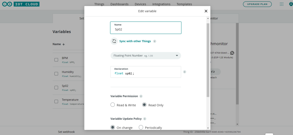
Then you need to create a Thing first. For that, click on add variable.

Name the variable anything like Sp02. In the variable type, select Floating Point Number. So an automatic declaration of variables will be done. Now set the variable permission to Read-only. Then click on Add variable button to create the first variable.
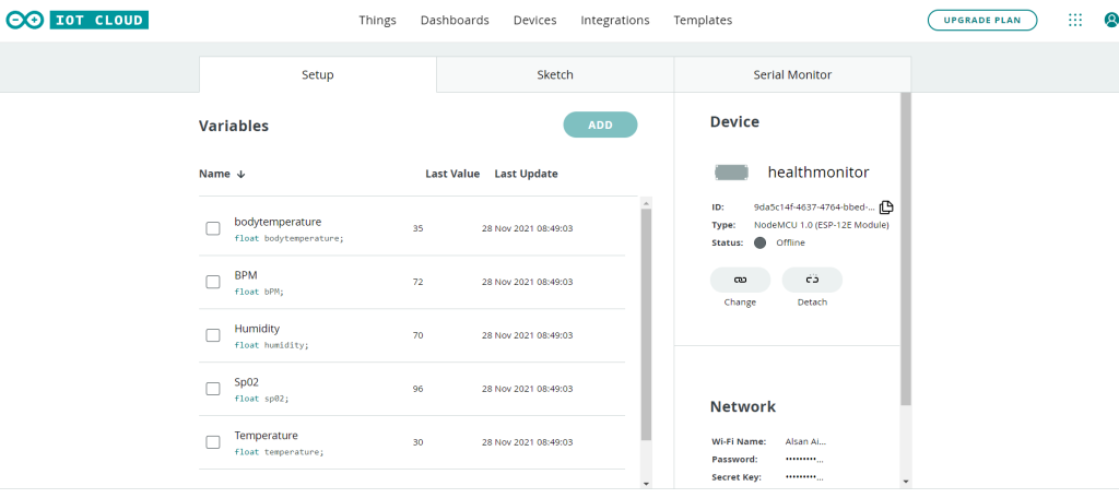
Similarly, create other three variables with names bodytemperature, BPM, Temperature, and Humidity.
Now, we need to configure a device as well. For that, select the device option. From the list, select a 3rd party device. Then select ESP8266. From this list, select NodeMCU1.0 ESP-12E Module.

Click to continue and give any name to the device. Give any name like “Smart Home/Health Monitor” Then click next.

So device ID & Secret Key is created here. Save this device ID for the coding part. Or simply download this PDF File which has the information of Secret Key. Then click on continue.

Now again, you need to set up the Network Credentials. So input your SSID, Password, and Secret Key that you created earlier. Finally, everything is set now.

Go to the dashboard. Here we need to build a dashboard.
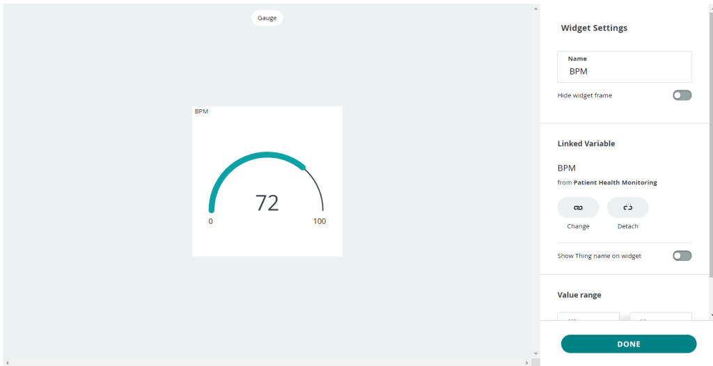
From the edit option, add a variable. So select Gauge. Give it a name BPM. Then link a variable. Click on Done. Similarly, add 4 more variables for 4 different health parameters and link the variable to them. You can arrange and resize the widget as your wish.
So finally, we are done with the IoT dashboard setup.
Source Code/Program
Let’s go to the sketch for Patient Health Monitoring System using Arduino IoT Cloud with ESP8266
There are 5 variables of floating-point number type automatically declared.
  float bodytemperature;
  float bPM;
  float sp02;
  float temperature;
  float humidity;
Next, we start the code by including the following libraries: thingProperties.h library is used for connecting the ESP8266 board to the Wi-Fi network and setting up a connection with IoT Cloud. Wire. h library is for communicating any I2C device not just the MAX30100 Pulse Oximeter sensor. MAX30100_PulseOximeter.h for reading BPM and Sp02 from the oximeter sensor. OneWire.h and DallasTemperature.h library for reading data from the DS18B20 temperature sensor. Finally, DHT.h for grabbing Humidity and Temperature from DHT11/DHT22 sensor.
#include "thingProperties.h"
#include <Wire.h>
#include "MAX30100_PulseOximeter.h"
#include <OneWire.h>
#include <DallasTemperature.h>
#include "DHT.h"
Here we defined the DHT sensor type, its signal pin interfaced with NodeMCU. Similarly, Dallas Temperature DS18B20 sensor pin and reporting period of 1000ms for MAX30100 sensor is also defined. We also Initialize DHT sensor, Pulse Oximeter sensor, and DS18B20 Dallas Temperature sensor.
#define DHTTYPE DHT22
#define REPORTING_PERIOD_MS 1000
#define DS18B20 2 //D4 pin= GPIO pin 2

PulseOximeter pox;
uint8_t DHTPin = 14; //D5 pin= GPIO pin 14
DHT dht(DHTPin, DHTTYPE);
uint32_t tsLastReport = 0;
OneWire oneWire(DS18B20);
DallasTemperature sensors(&oneWire);
Begin serial debugging at a baud rate of 115200. Define NodeMCU D0 pin (GPIO 16) as output. Test the DHT 22 sensor and connect your microcontroller to the Wi-Fi network. After a successful connection, it will connect to the Arduino IoT Cloud. Finally, Initialize the MAX30100 sensor for testing and print results on the serial monitor.
// Initialize serial and wait for port to open:
  Serial.begin(115200);
  pinMode(16, OUTPUT);
  pinMode(DHTPin, INPUT);
  dht.begin();
  // This delay gives the chance to wait for a Serial Monitor without blocking if none is found
  delay(1500);

  // Defined in thingProperties.h
  initProperties();

  // Connect to Arduino IoT Cloud
  ArduinoCloud.begin(ArduinoIoTPreferredConnection);


  setDebugMessageLevel(2);
  ArduinoCloud.printDebugInfo();

  Serial.print("Initializing Pulse Oximeter..");

  if (!pox.begin())
  {
    Serial.println("FAILED");
    for (;;);
  }
  else
  {
    Serial.println("SUCCESS");
    pox.setOnBeatDetectedCallback(onBeatDetected);
  }
  pox.setIRLedCurrent(MAX30100_LED_CURR_7_6MA);
}
Request sensor readings from all the sensors and print those five parameters (temperature, humidity, BPM, Sp02, and body temperature) on the serial monitor. And update all the values to the Arduino IoT Cloud Dashboard.
  pox.update();
  ArduinoCloud.update();
  // Your code here
  temperature = dht.readTemperature(); // Gets the values of the temperature
  humidity = dht.readHumidity(); // Gets the values of the humidity
  bPM = pox.getHeartRate();
  sp02 = pox.getSpO2();
  bodytemperature = sensors.getTempCByIndex(0);


  if (millis() - tsLastReport > REPORTING_PERIOD_MS)
  {
    Serial.print("Heart rate:");
    Serial.print(bPM);
    Serial.print(" bpm / SpO2:");
    Serial.print(sp02);
    Serial.println(" %");
    Serial.print("Room Temperature: ");
    Serial.print(temperature);
    Serial.println("°C");
    Serial.print("Room Humidity: ");
    Serial.print(humidity);
    Serial.println("%");
    Serial.print("Body Temperature: ");
    Serial.print(bodytemperature);
    Serial.println("°C");
  tsLastReport = millis();
  }
}
Below is the complete code that you can use for this project.
IoT_based_Patient_Health_Monitoring_System.ino
/*
  Sketch generated by the Arduino IoT Cloud Thing "Patient Health Monitoring"
  https://create.arduino.cc/cloud/things/258e949e-ba1f-4085-8340-163590236794

  Arduino IoT Cloud Variables description

  The following variables are automatically generated and updated when changes are made to the Thing

  float bodytemperature;
  float bPM;
  float sp02;
  float temperature;
  float humidity;

  Variables which are marked as READ/WRITE in the Cloud Thing will also have functions
  which are called when their values are changed from the Dashboard.
  These functions are generated with the Thing and added at the end of this sketch.
*/

#include "thingProperties.h"
#include <Wire.h>
#include "MAX30100_PulseOximeter.h"
#include <OneWire.h>
#include <DallasTemperature.h>
#include "DHT.h"
#define DHTTYPE DHT22
#define REPORTING_PERIOD_MS 1000
#define DS18B20 2 //D4 pin= GPIO pin 2

PulseOximeter pox;
uint8_t DHTPin = 14; //D5 pin= GPIO pin 14
DHT dht(DHTPin, DHTTYPE);
uint32_t tsLastReport = 0;

OneWire oneWire(DS18B20);
DallasTemperature sensors(&oneWire);

void onBeatDetected()
{
  Serial.println("Beat Detected!");
}

void setup() {
  // Initialize serial and wait for port to open:
  Serial.begin(115200);
  pinMode(16, OUTPUT);
  pinMode(DHTPin, INPUT);
  dht.begin();
  // This delay gives the chance to wait for a Serial Monitor without blocking if none is found
  delay(1500);

  // Defined in thingProperties.h
  initProperties();

  // Connect to Arduino IoT Cloud
  ArduinoCloud.begin(ArduinoIoTPreferredConnection);

  /*
     The following function allows you to obtain more information
     related to the state of network and IoT Cloud connection and errors
     the higher number the more granular information you’ll get.
     The default is 0 (only errors).
     Maximum is 4
 */
  setDebugMessageLevel(2);
  ArduinoCloud.printDebugInfo();

  Serial.print("Initializing Pulse Oximeter..");

  if (!pox.begin())
  {
    Serial.println("FAILED");
    for (;;);
  }
  else
  {
    Serial.println("SUCCESS");
    pox.setOnBeatDetectedCallback(onBeatDetected);
  }
  pox.setIRLedCurrent(MAX30100_LED_CURR_7_6MA);
}

void loop() {
  pox.update();
  ArduinoCloud.update();
  // Your code here
  temperature = dht.readTemperature(); // Gets the values of the temperature
  humidity = dht.readHumidity(); // Gets the values of the humidity
  bPM = pox.getHeartRate();
  sp02 = pox.getSpO2();
  bodytemperature = sensors.getTempCByIndex(0);


  if (millis() - tsLastReport > REPORTING_PERIOD_MS)
  {
    Serial.print("Heart rate:");
    Serial.print(bPM);
    Serial.print(" bpm / SpO2:");
    Serial.print(sp02);
    Serial.println(" %");
    Serial.print("Room Temperature: ");
    Serial.print(temperature);
    Serial.println("°C");
    Serial.print("Room Humidity: ");
    Serial.print(humidity);
    Serial.println("%");
    Serial.print("Body Temperature: ");
    Serial.print(bodytemperature);
    Serial.println("°C");
  tsLastReport = millis();
  }
}
thingproperties.h
// Code generated by Arduino IoT Cloud, DO NOT EDIT.

#include <ArduinoIoTCloud.h>
#include <Arduino_ConnectionHandler.h>


const char THING_ID[]           = "258e949e-ba1f-4085-8540-163590236794";
const char DEVICE_LOGIN_NAME[]  = "9da5c14f-4637-4764-2bed-12aa2f4ac9e5";

const char SSID[]               = SECRET_SSID;    // Network SSID (name)
const char PASS[]               = SECRET_PASS;    // Network password (use for WPA, or use as key for WEP)
const char DEVICE_KEY[]  = SECRET_DEVICE_KEY;    // Secret device password


float bodytemperature;
float bPM;
float sp02;
float temperature;
float humidity;

void initProperties(){

  ArduinoCloud.setBoardId(DEVICE_LOGIN_NAME);
  ArduinoCloud.setSecretDeviceKey(DEVICE_KEY);
  ArduinoCloud.setThingId(THING_ID);
  ArduinoCloud.addProperty(bodytemperature, READ, ON_CHANGE, NULL);
  ArduinoCloud.addProperty(bPM, READ, ON_CHANGE, NULL);
  ArduinoCloud.addProperty(sp02, READ, ON_CHANGE, NULL);
  ArduinoCloud.addProperty(temperature, READ, ON_CHANGE, NULL);
  ArduinoCloud.addProperty(humidity, READ, ON_CHANGE, NULL);

}

WiFiConnectionHandler ArduinoIoTPreferredConnection(SSID, PASS);
Secrets.h
#define SECRET_SSID "xxx-xxx"
#define SECRET_PASS "xx-xx-xx"
#define SECRET_DEVICE_KEY "xxxx-xxxxx-xxxx"
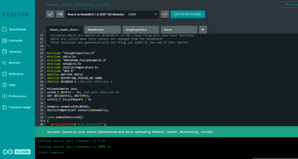
Apart from the code part, we need to upload the code. But before that, we need to install an Agent to flash the code directly from the browser. Follow the instruction on your screen to install the agent.
Once the driver is installed, the COM port will appear. Then select the ESP8266 NodeMCU Board from the list and the COM port as well. Then, upload the code. It will take some time to upload the code and when it’s done, some upload success message will appear.
Testing: Patient Health Monitoring System using Arduino IoT Cloud with ESP8266
After uploading the code, open the Serial Monitor. It will show WiFi connection is established and then the device is connected to Arduino IoT Cloud Dashboard.

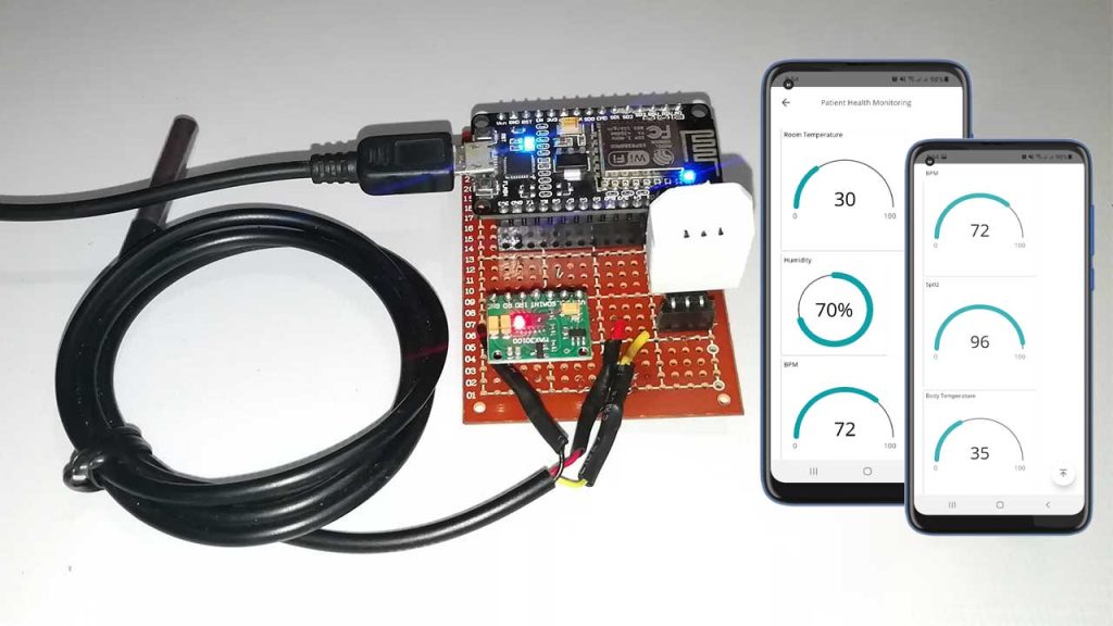
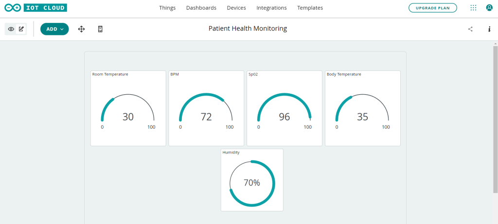
Open the dashboard now, so you can monitor the real-time data of the room temperature, room humidity, Heart Rate, Blood Oxygen Level, and body temperature, etc., as shown in the image below.
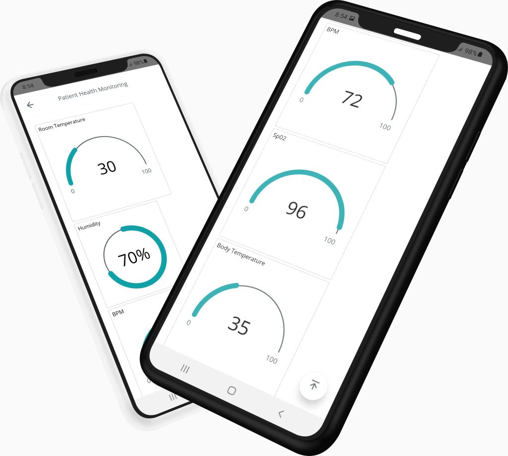
You can also monitor those health parameters from Mobile Dashboard. For that install Arduino IoT Remote from Playstore. Sign in using the same ID and password. Open the dashboard to control the appliances easily.
Also Read:
- MAX30100 Pulse Oximeter webserver using NodeMCU ESP8266
- IoT based Pulse Oximeter using ESP8266 & Blynk
Conclusion
This tutorial shows you how to make an IoT Based Patient Health Monitoring System Using ESP8266 NodeMCU & Arduino IoT Cloud. I hope this tutorial was interesting to you. If you need any type of help related to this project, then let me know in the comment section below.


Hi sir
Please make a youtube video about this project and explain the coding portion