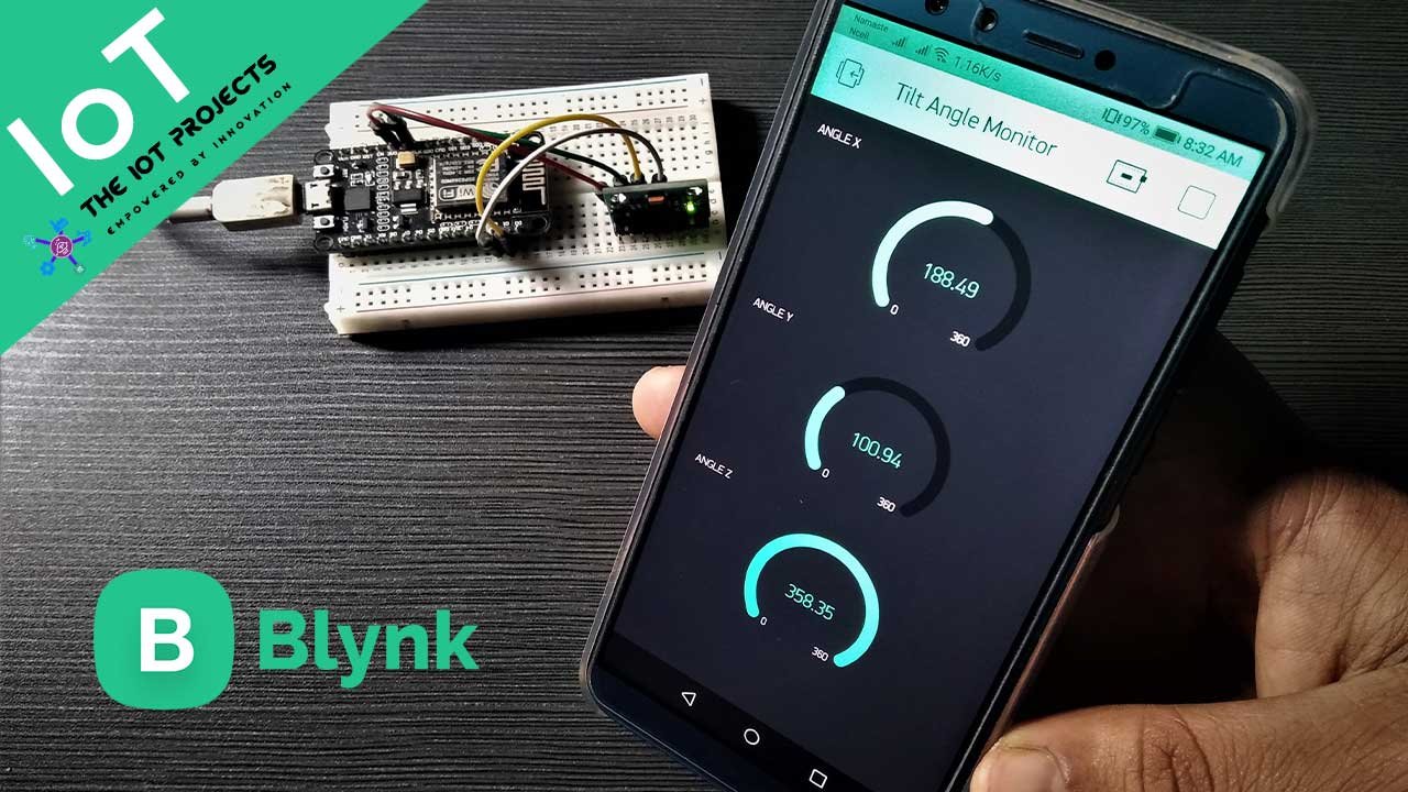
Today we will learn to interface MPU6050 Sensor with NodeMCU to Monitor MPU6050 Tilt Angle on Blynk IoT Application.
Introduction
In this post, we will learn how to Monitor MPU6050 Tilt Angle on Blynk using NodeMCU. This can be done by simply interfacing the MPU6050 6-axis Gyro/Accelerometer Sensor with NodeMCU. The Accelerometer sends X, Y, and Z acceleration forces. We need to convert those forces into X, Y, Z 3D angle to determine the 3D Orientation of the sensor. Then the measured tilt angle is sent to the Blynk Application using the Blynk cloud. So the tilt position can be monitored in IoT.
The gyroscope measures the position of rotation velocity or angle along with the X, Y, and Z-axis. It uses MEMS technology and the Coriolis effect for measurement. The outputs of the gyroscope are degrees per second, so to get the angular position, we just need to integrate the angular velocity.
You can refer to the previous post where we measured tilt angle using MPU6050 and send an SMS notification as fall detected when the defined threshold value is reached: IoT Based Fall Detection system using MPU6050 & NodeMCU ESP8266
Components Required
The following components are required to create this project. All components can be easily purchased from Amazon.
| S.N | Components | Description | Quantity | |
|---|---|---|---|---|
| 1. | NodeMCU | ESP8266 12E Board | 1 | https://amzn.to/3mTuL95 |
| 2. | MPU6050 6-axis Gyroscope/Accelerometer | Gyroscope + Accelerometer | 1 | https://amzn.to/39OEuKk |
| 3. | Breadboard | Solderless Breadboard MIni | 1 | https://amzn.to/3n33uRT |
| 4. | Jumper Wires | Connecting Wires | 4 | https://amzn.to/2JWSR44 |
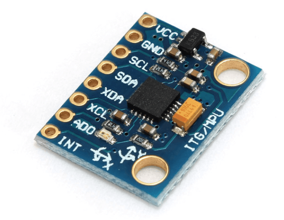
MPU6050 Gyroscope/Accelerometer Sensor
The InvenSense MPU-6050 sensor includes a MEMS accelerometer and a MEMS gyro on a single chip. This is perfect, as it includes 16-bits analog of digital conversion hardware for each channel. So it captures x, y, and z channels at the same time. The sensor uses the I2C-bus to interface with the Arduino.
The MPU6050 is not expensive, especially given the fact that it fits both an accelerometer and a gyroscope.
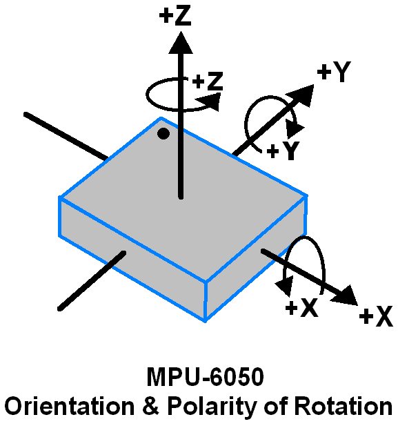
3-Axis Gyroscope:
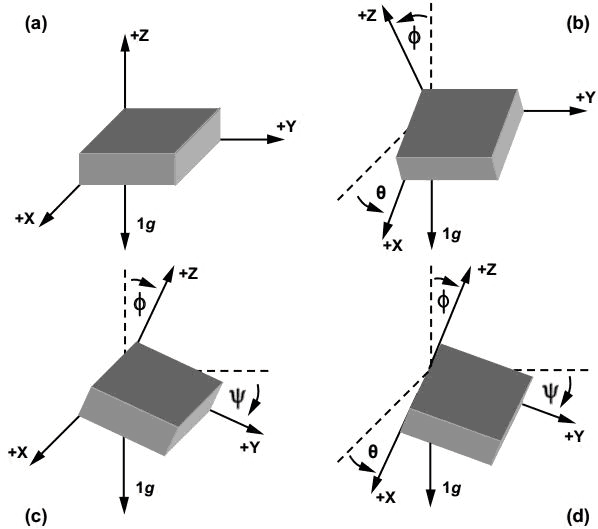
The MPU6050 consists of a 3-axis Gyroscope with Micro Electro Mechanical System(MEMS) technology. It is used to detect rotational velocity along the X, Y, Z axes as shown below figure.
3-Axis Accelerometer:
The MPU6050 consists of a 3-axis Accelerometer with Micro Electro Mechanical (MEMs) technology. It used to detect the angle of tilt or inclination along the X, Y, and Z axes as shown below figure.
Circuit: Monitor MPU6050 Tilt Angle on Blynk using NodeMCU
Here is the circuit diagram for interfacing the MPU6050 Gyro/Accelerometer with NodeMCU ESP8266. The circuit can be assembled on a breadboard.
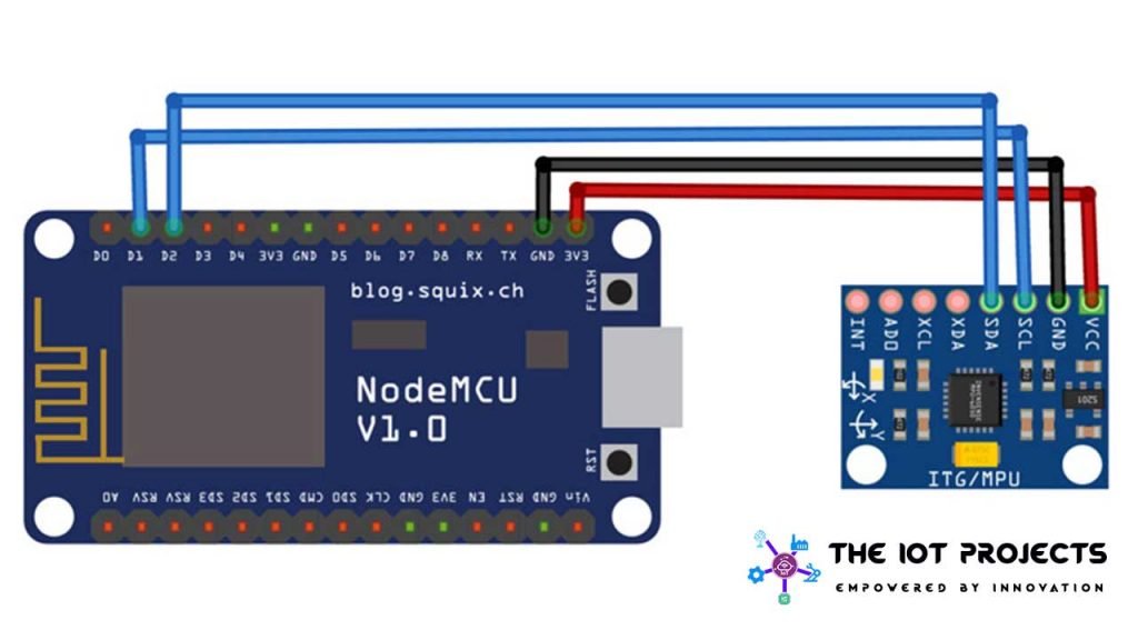
The MPU6050 is an I2C Module. So we need only 4 wires for interfacing it with NodeCMU. The SDA pins of MPU6050 modules is connected to D2 of NodeMCU ESP8266 & SCL to D1. Supply 3.3V power and GND to MPU6050 modules.
Setting Up Blynk IoT Application for MPU6050 Tilt Monitoring
Blynk is an application that runs on both Android and IOS devices to control any IoT based application using Smartphones. This allows you to create your Graphical user interface for your IoT applications. Here we will set up the Blynk application to monitor MPU6050 Angles over Wi-Fi using NodeMCU ESP8266.
Download and install the Blynk app from the Google Play Store. IOS users can download from the App Store. Once the installation is complete, open the app and sign-up using your email address and password.
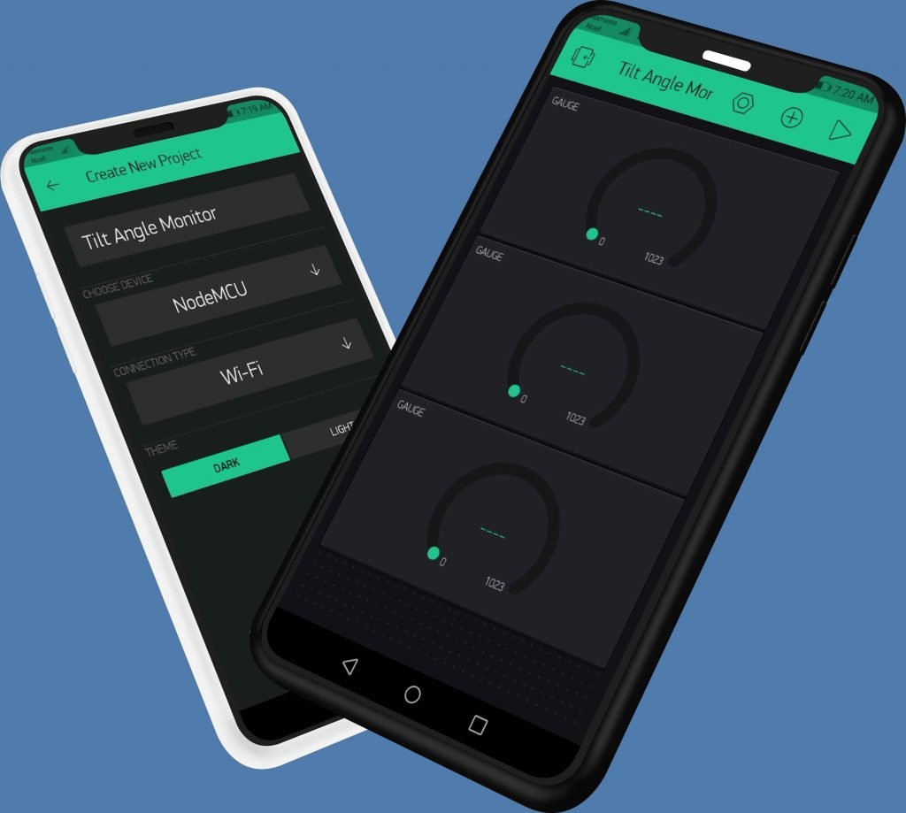
- Click on create a new project
- Provide the Name of your project
- Choose NodeMCU Board
- Select connection type as Wi-Fi, then click on Create Button.
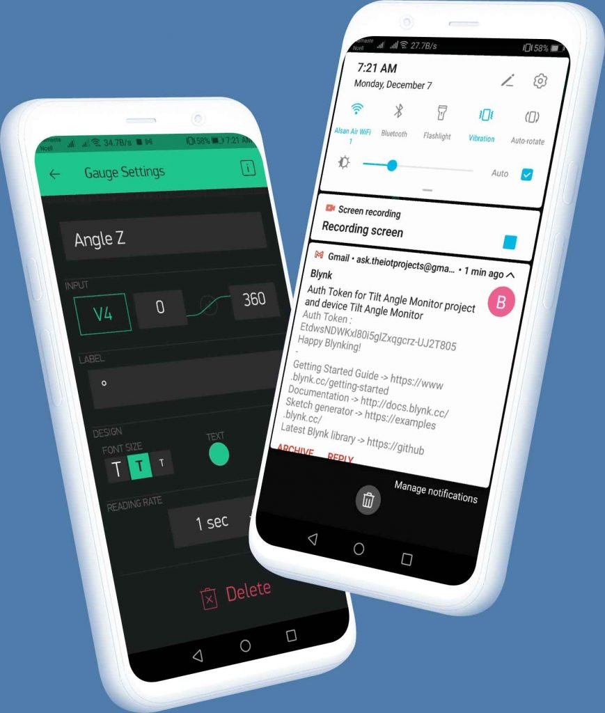
- The Blynk authentication token is sent to your email address. (We need it later on programming)
- Now, click on the (+) icon at the top right corner of the screen.
- Search for Gauge and add 3 Gauge to your main screen.
- Click on the first Gauge.
- Name the first gauge as “Angle X”
- Set the Input Pin to Virtual Pin V2 and choose the value range to 360.
- Write the label as a degree.
- Choose the refresh rate as 1sec.
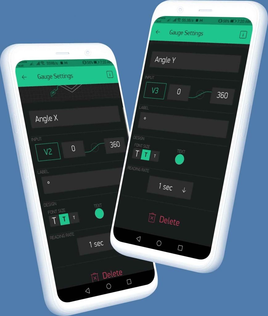
- Similarly, do the same for Angle Y and Angle Z but make sure the Input pin for Angle Yis Virtual pin V3 and V4 for Angle Z.
Finally, the Blynk App setup for Monitoring MPU6050 Tilt Angle on Blynk using NodeMCU is completed.
Source Code/Program
The source code/program for Monitoring MPU6050 Tilt Angle on Blynk using NodeMCU is given below. We will need Blynk libraries to compile the code. So download the libraries from the link below and add it to Arduino Library.
#include<Wire.h>
#define BLYNK_PRINT Serial
#include <Blynk.h>
#include <ESP8266WiFi.h>
#include <BlynkSimpleEsp8266.h>Make sure to do the following changes in the program code. Change Your Wi-Fi SSDI & Password. Also, change the Blynk Authentication Token as well.
char auth[] = "LHvT-tj0Uoy9xXfjGshKOyRk_cVYZhZd";       // You should get Auth Token in the Blynk App.
char ssid[] = "Alsan";                       // Your WiFi credentials.
char pass[] = "1234567890";
Final code for Monitoring MPU6050 Tilt Angle on Blynk using NodeMCU
#include<Wire.h>
#define BLYNK_PRINT Serial
#include <Blynk.h>
#include <ESP8266WiFi.h>
#include <BlynkSimpleEsp8266.h>
char auth[] = "LHvT-tj0Uoy9xXfjGshKOyRk_cVYZhZd"; // You should get Auth Token in the Blynk App.
char ssid[] = "Alsan"; // Your WiFi credentials.
char pass[] = "1234567890";
const int MPU_addr=0x68;
int16_t AcX,AcY,AcZ,Tmp,GyX,GyY,GyZ;
int minVal=265;
int maxVal=402;
double x;
double y;
double z;
void setup(){
Wire.begin();
Wire.beginTransmission(MPU_addr);
Wire.write(0x6B);
Wire.write(0);
Wire.endTransmission(true);
Serial.begin(9600);
Blynk.begin(auth, ssid, pass);
}
void loop(){
Blynk.run();
Wire.beginTransmission(MPU_addr);
Wire.write(0x3B);
Wire.endTransmission(false);
Wire.requestFrom(MPU_addr,14,true);
AcX=Wire.read()<<8|Wire.read();
AcY=Wire.read()<<8|Wire.read();
AcZ=Wire.read()<<8|Wire.read();
int xAng = map(AcX,minVal,maxVal,-90,90);
int yAng = map(AcY,minVal,maxVal,-90,90);
int zAng = map(AcZ,minVal,maxVal,-90,90);
x= RAD_TO_DEG * (atan2(-yAng, -zAng)+PI);
y= RAD_TO_DEG * (atan2(-xAng, -zAng)+PI);
z= RAD_TO_DEG * (atan2(-yAng, -xAng)+PI);
Serial.print("AngleX= ");
Serial.println(x);
Serial.print("AngleY= ");
Serial.println(y);
Serial.print("AngleZ= ");
Serial.println(z);
Serial.println("-----------------------------------------");
Blynk.virtualWrite(V2, x);
Blynk.virtualWrite(V3, y);
Blynk.virtualWrite(V4, z);
delay(1000);
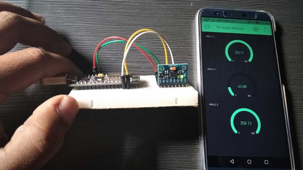
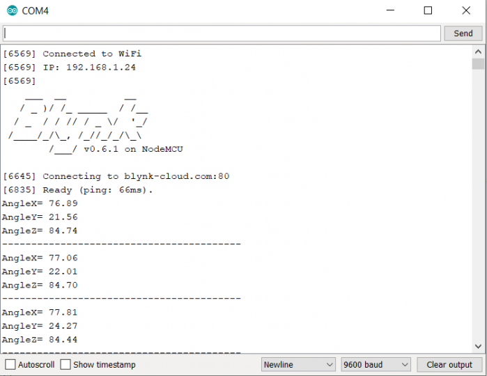
}Demonstration: MPU6050 Tilt Angle on IoT Blynk
Once a dial code has been uploaded, you can click on the serial monitor to check the output drips. To determine the position of any position of the X, Y, and Z-axis MP6060 Gyroscope/Accelerometer is required to be tilted. The same tilt angles can be observed on the Blynk Application.
Conclusion:
So, we have completed Monitoring MPU6050 Tilt Angle on IoT Blynk App using NodeMCU. We hope this tutorial was helpful to you. If you have any doubts or queries do let us know them here.
Recommend Readings:
- IoT Based Voice Controlled Home Automation Using NodeMCU & Android
- Home Automation with ESP8266 Web Server & Relay Module Control Appliances from Local Network
- ESP8266 Manual Wifi Configuration with EEPROM without Hard-Code
- Simple Weather station using Arduino & BME280 Barometric Pressure Sensor
- Top 10 Coolest IoT Devices of 2020
- ESP8266 Data Logger to Upload Data on Webserver
- IoT based Silent Intruder Alarm using Arduino
- IoT Weather Station using DHT11 Sensor


