IoT Based Bidirectional Visitor Counter using ESP8266 & Blynk
IoT Based Visitor Counter using NodeMCU & IR Sensor
Overview: IoT based Visitor Counter
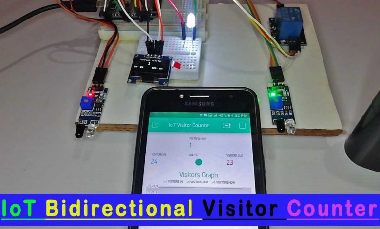
Today in this project, will make IoT Based Bidirectional Visitor Counter using NodeMCU ESP8266 & Blynk IoT cloud. This project is useful for monitoring the total number of visitors entering, exiting, and current visitors available from any part of the world using the Blynk IoT cloud platform. Infrared or IR Sensors are used to count the total number of incoming and outcoming visitors. The Visitors’ data is uploaded automatically to Blynk cloud using the NodeMCU ESP8266 Wi-Fi Module.
You can use this ESP8266 NodeMCU based IoT Bidirectional Visitor counter in the hall, shopping mall, office entrance gate to count the total number of visitors. This device counts the total number of visitors entering through the gate & also counts the total number of visitors exiting through the different gates. Basically, it calculates the total number of current visitors by subtracting the outgoing visitor from the incoming visitor. When a single person enters the room, the light turns on automatically. Whenever there are no visitors present in the room, the light turns off automatically.
Previously, we have made the Visitor Counter Project using Arduino & OLED Display. But this time we will send the data to the Blynk cloud instead of simply watching it on OLED Display.
Components Required
We can make this IoT Bidirectional Visitor Counter using ESP8266 Wi-Fi Module, a pair of IR Sensor, SSD1306 OLED Display, and a Relay Module. The list of components that you need for creating an IoT Bidirectional Visitor Counter is as follows.
| S.N | Components Name | Description | Quantity | |
|---|---|---|---|---|
| 1 | NodeMCU | ESP8266 12E Board | 1 | https://amzn.to/3mTuL95 |
| 2 | IR Sensor | IR Infrared Sensor Module | 2 | https://amzn.to/3dYWK5f |
| 3 | OLED Display | 0.96" I2C OLED Display | 1 | https://amzn.to/32WRubSv |
| 4 | Relay Module | 5V 1 Channel Relay Module | 1 | https://amzn.to/3gJNJyJ |
| 5 | Jumper Wires | Jumper Cables breadboard friendly | 20 | https://amzn.to/3vw9ZAt |
| 6 | Breadboard | Mini Breadboard | 1 | https://amzn.to/2NP2UKL |
Learn more about IR sensors as Visitor Detectors from our previous post.
IoT Bidirectional Visitor Counter Circuit or Schematic
The Circuit Diagram for IoT Bidirectional Visitor Counter using NodeMCU ESP8266 is very simple. I designed the circuit diagram for this project using Fritzing Software.
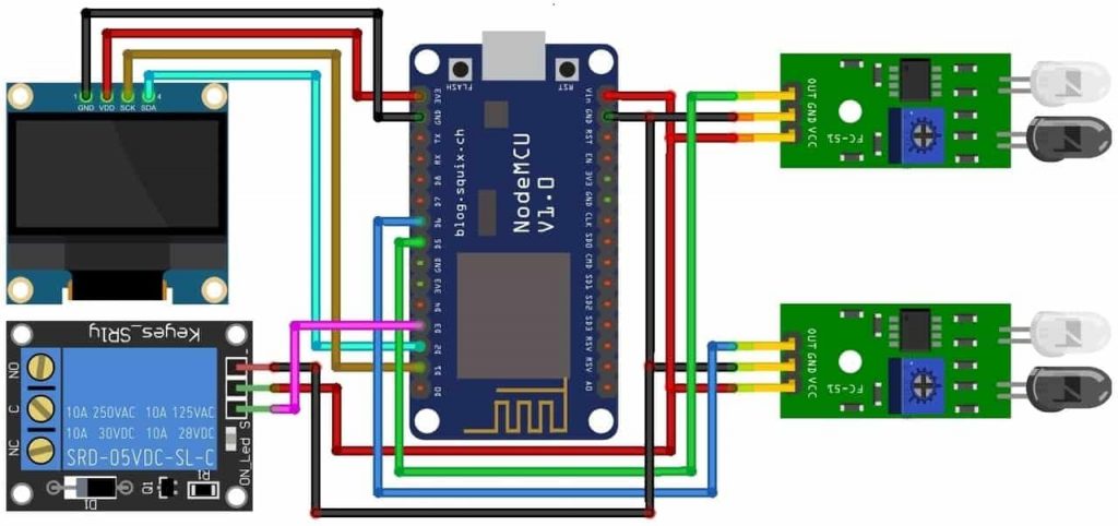
Connect the I2C Pins (SDA & SCL) of 0.96″ SSD1306 OLED Display with NodeMCU D2 & D1 Pins. Interface the output pin of the pair of IR Sensors to the D5 & D6 pin of NodeMCU. We will use one of the IR Sensors in the Entrance gate for counting incoming visitors and the other in the exit gate for counting the outgoing visitor. Similarly, connect a 5V Relay Module to the D4 Pin of ESP8266. Both the IR Sensors and Relay Module works at 5V VCC. You can supply a 5V power supply from a NodeMCU Vin pin.
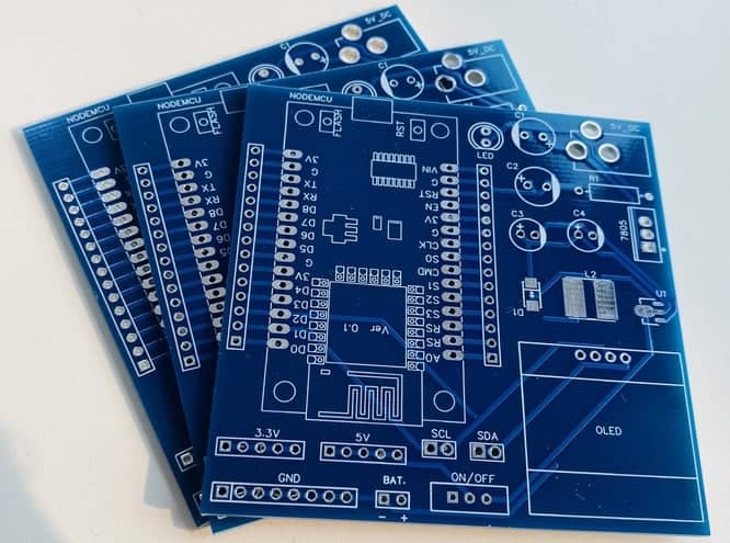
PCB Designing & Ordering
You can simply assemble the circuit on a breadboard. But if you don’t want to assemble the circuit on a breadboard, you can follow this schematic and build your own PCB. You can download the Gerber file of my PCB Design from the link attached below. The PCB looks like the image shown below.
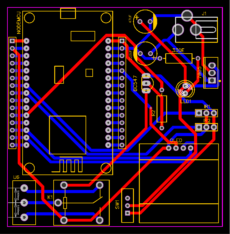
I provided the Gerber File for IoT Based Bidirectional Visitor Counter with Automatic Light Control system PCB below.
You can simply download the Gerber File and order your custom PCB from PCBWay

Visit the PCBWay official website by clicking here: https://www.PCBWay.com/. Simply upload your Gerber File to the Website and place an order. The reason behind most of the people trusting PCBWay for PCB & PCBA Services is because of their quality. The PCB quality is superb and has a very high finish, as expected.
More Interesting Projects
- IoT Fall Detector Using MPU6050 & ESP8266
- Portable Wi-Fi Repeater using ESP8266 NodeMCU
- Connect RFID to PHP & MySQL Database with NodeMcu ESP8266
- Interfacing PIR Sensor with ESP8266 and EasyIoT
- IoT Based RFID Attendance System using ESP32
- Internet Clock Using NodeMCU ESP8266 and 16×2 LCD without RTC Module
Setting Up Blynk Application
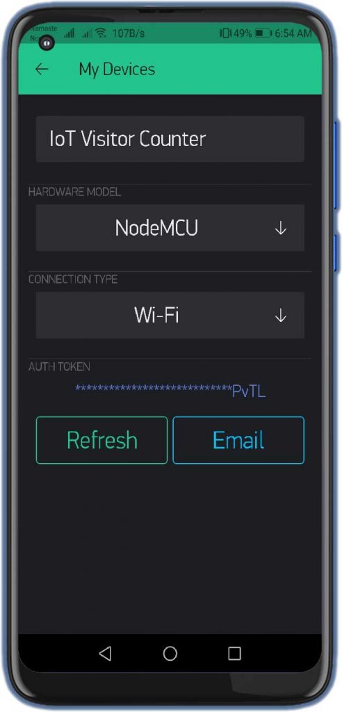
We need to set up the Blynk App to receive the Visitor Counter data from the ESP8266 NodeMCU board. To set up Blynk Application, Download & Install the Application on your smartphone. Available in both Android PlayStore and IOS AppStore. Open the App & create a New Account using your email address.
- Click on create a new project
- Provide the Name of your project as “IoT Visitor Counter”
- Choose NodeMCU Dev Board
- Select connection type as Wi-Fi, then click on Create Button.
- They sent the Blynk authentication token to your email address. (We need it later on programming)
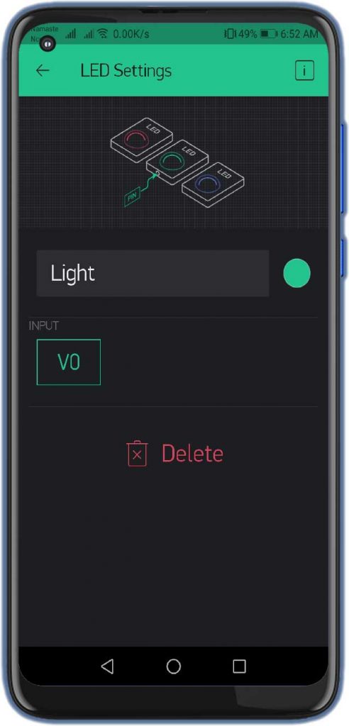
- Now, click on the (+) icon at the top right corner of the screen.
- Search for the “Value Display” widget and add 3 of them to your main screen.
- Also, add Super Chart Widget to the main screen.
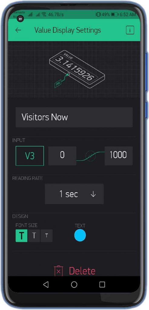
- Click on the First Value Display.
- Name it as “Visitors Now”
- Set the Input Pin to Virtual Pin V3, Enter input Range & Choose the refresh rate as 1sec.
- You can set colors and fonts size according to your need.
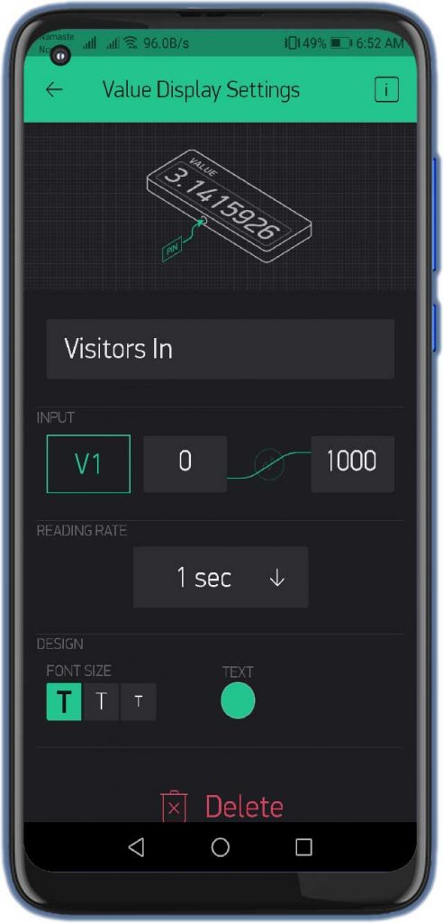
Similarly, do the same for Visitors In, Out with the help of the images below.
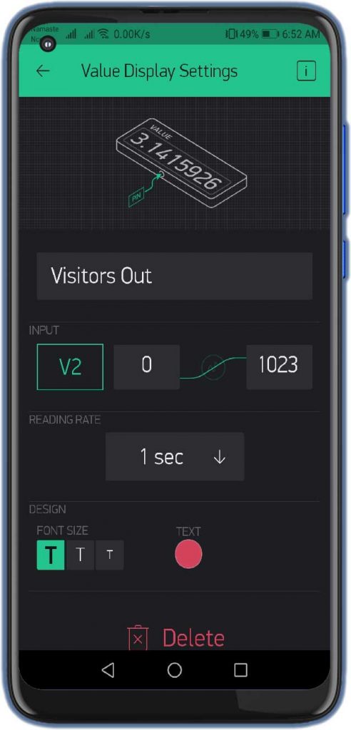
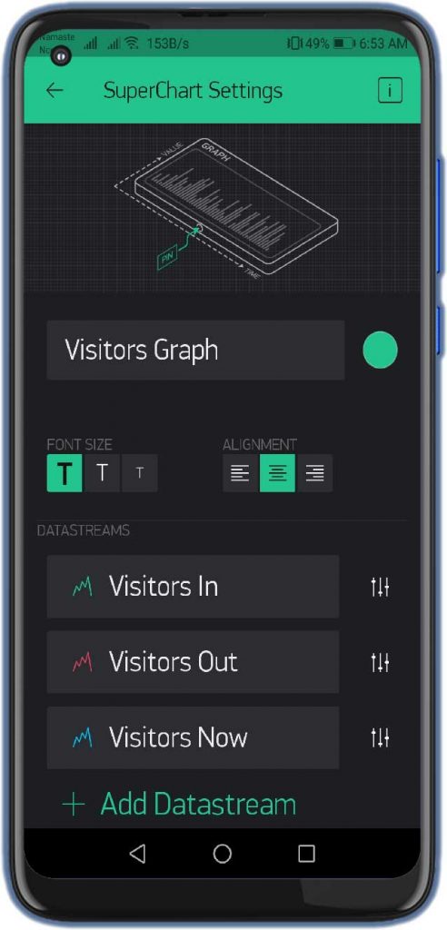
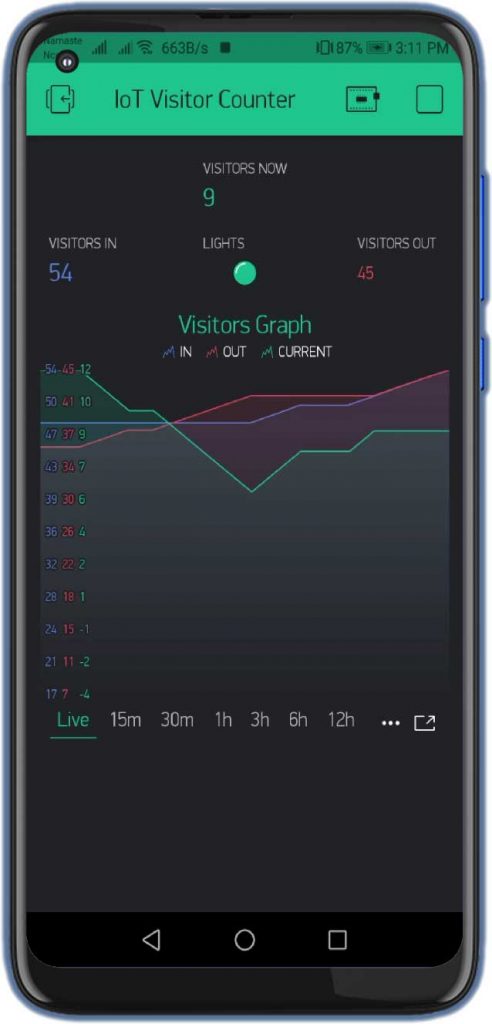
Now, click on the Super Chart widget and Name it as “Visitors Graphs” Add three datastream as Visitors In, Out, and Now with their respective virtual pins.
Finally, the Blynk App setup for IoT Bidirectional Visitor Counter using NodeMCU ESP8266 is completed.
Also Read:
Home Automation with Arduino IoT Cloud using ESP8266
IoT Based Pulse Oximeter Using ESP8266 & Blynk
Source Code/Program
The Source Code for ESP8266 based IoT Bidirectional Visitor Counter and Automatic Light Control System is given below. The code requires SSD1306 & Adafruit GFX library & Blynk Library for compilation. First, download the required libraries and add them to the Arduino IDE.
From this code part, change the Wi-Fi SSID, Password & Blynk Authentication Token. Use the same API Token sent to your email address. You can now copy the code and upload it to the NodeMCU ESP8266 Board.
char auth[] = "xxxxx-xxxxx-xxxx";       // You should get Auth Token in the Blynk App.
char ssid[] = "xxxxx-xxxxx-xxxx";                       // Your WiFi credentials.
char pass[] = "xxxxx-xxxxx-xxxx";
Final Program Code for IoT based Bidirectional Visitor Counter & Automatic Light Control using NodeMCU.
#include <Wire.h>
#include <Adafruit_GFX.h>
#include <Adafruit_SSD1306.h>
#include <Blynk.h>
#include <ESP8266WiFi.h>
#include <BlynkSimpleEsp8266.h>

#define SCREEN_WIDTH 128    // OLED display width, in pixels
#define SCREEN_HEIGHT 64    // OLED display height, in pixels
#define OLED_RESET -1       // Reset pin # (or -1 if sharing Arduino reset pin)
Adafruit_SSD1306 display(SCREEN_WIDTH, SCREEN_HEIGHT, &Wire, OLED_RESET);

char auth[] = "xxxxx-xxxxx-xxxx";       // You should get Auth Token in the Blynk App.
char ssid[] = "xxxxx-xxxxx-xxxx";                       // Your WiFi credentials.
char pass[] = "xxxxx-xxxxx-xxxx";

#define inSensor 14 //D5
#define outSensor 12 //D6

int inStatus;
int outStatus;

int countin = 0;
int countout = 0;

int in;
int out;
int now;

#define relay 0 //D3
WidgetLED light(V0);

void setup()
{
  Serial.begin(115200);
  Blynk.begin(auth, ssid, pass);
  delay(1000);  // wait a second
  display.begin(SSD1306_SWITCHCAPVCC, 0x3C); //initialize with the I2C addr 0x3C (128x64)
  delay(2000);
  pinMode(inSensor, INPUT);
  pinMode(outSensor, INPUT);
  pinMode(relay, OUTPUT);
  digitalWrite(relay, HIGH);

  Serial.println("Visitor Counter Demo");
  display.clearDisplay();
  display.setTextSize(2);
  display.setTextColor(WHITE);
  display.setCursor(20, 20);
  display.print("Visitor");
  display.setCursor(20, 40);
  display.print("Counter");
  display.display();
  delay(3000);
}

void loop()
{
  Blynk.run(); // Initiates Blynk
  inStatus =  digitalRead(inSensor);
  outStatus = digitalRead(outSensor);
  if (inStatus == 0)
  {
    in = countin++;
  }

  if (outStatus == 0)
  {
    out = countout++;
  }

  now = in - out;

  if (now <= 0)
  {
    digitalWrite(relay, HIGH);
    light.off();
    display.clearDisplay();
    display.setTextSize(2);
    display.setTextColor(WHITE);
    display.setCursor(0, 15);
    display.print("No Visitor");
    display.setCursor(5, 40);
    display.print("Light Off");
    display.display();
    Serial.println("No Visitors! Light Off");
    delay(500);
  }
  else
  {
    digitalWrite(relay, LOW);
    light.on();

    display.clearDisplay();
    display.setTextColor(WHITE);

    display.setTextSize(1);
    display.setCursor(15, 0);
    display.print("Current Visitor");
    display.setTextSize(2);
    display.setCursor(50, 15);
    display.print(now);

    display.setTextSize(1);
    display.setCursor(0, 40);
    display.print("IN: ");
    display.print(in);

    display.setTextSize(1);
    display.setCursor(70, 40);
    display.print("OUT: ");
    display.print(out);

    display.display();
    Serial.print("Current Visitor: ");
    Serial.println(now);
    Serial.print("IN: ");
    Serial.println(in);
    Serial.print("OUT: ");
    Serial.println(out);
    delay(500);
  }
  Blynk.virtualWrite(V1, in); // Visitors In
  Blynk.virtualWrite(V2, out); // Visitors Out
  Blynk.virtualWrite(V3, now); // Current Visitors
  delay(1000);
}
Testing IoT ESP8266 Based Visitor Counter Project
The above code for the ESP8266 based IoT visitor counter with Blynk fulfills all the requirements of the project. You can upload the code to the ESP8266 Wi-Fi Module. Once you upload the code, the ESP8266 board will connect to the Blynk Cloud using your Wi-Fi Network. Once it connects to the network, you can open the Serial Monitor. You can simply check all the details on Serial Monitor.
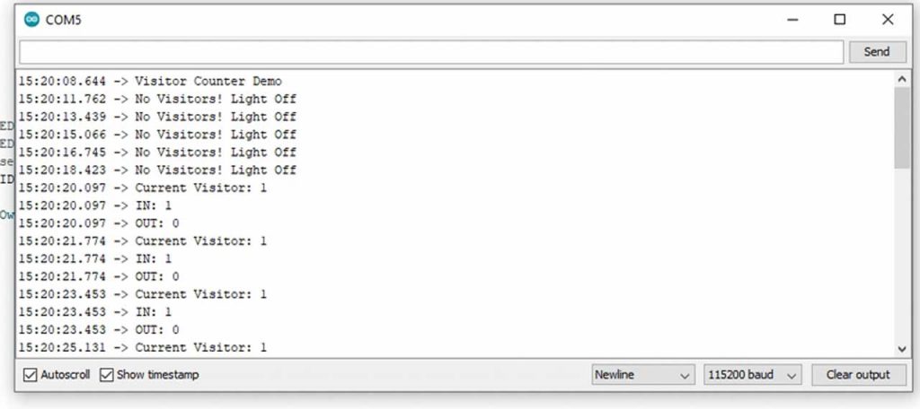
The Serial Monitor will display the connection status of the Wi-Fi Network along with the IP Address. If there is a successful Wi-Fi connection and a further connection to Blynk IoT Cloud. It will update automatically the data after every 1-second interval. The Serial Monitor will also display the number of visitors entering, exiting, current visitors & relay Status.
On the Hardware Part, when there are no visitors, the OLED Display will simply show “No Visitors Lights OFF”.
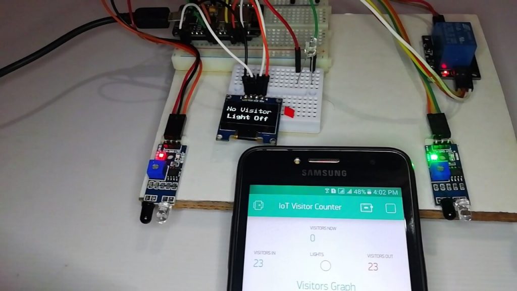
Similarly, when someone enters the room, the light will turn on automatically and OLED Display shows the number of incoming, outgoing, and current visitors.
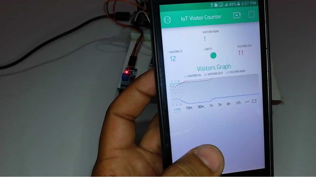
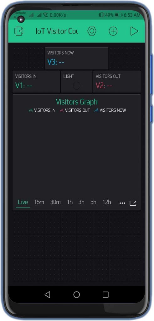
Monitoring Visitors Status Online on Blynk App
As soon as we connected the device to the Wi-Fi and Blynk server, you will see the data appearing on the Blynk App. Here you will see the data for visitors. So the data only changes when an event occurs. You will get a beautiful real-time dashboard as shown in the image below.
Video Tutorial & Guide
Conclusion
So, that’s pretty much for this tutorial. I hope you enjoyed making your IoT Based Bidirectional Visitor Counter using ESP8266 & Blynk. If you did, don’t forget to share this article with your friends. Want help? let me know in the comment section below.


can i get a BlynkSimpleShieldEsp8266.h library
just wonder how to use it in real world. If I would like to place it in school bus which has two entry door and exit door. Ideally one esp8266 with two IR sensors which the exit checking sensor needs to have long wiring from entry door to exit door( 1-3 metres). Or using two esp8266 communicate together for checking in-out visitor?
Use one ESP8266 and attach long wire on IR sensor. It works.
Thanks so much for your answer
can u please share the code for restriction in number of people can enter into the hall and number of seats available
can i get full circuit diagram with relay connection to light and NodeMCU ? cause i cannot see your connection Light (LED) relay with Node MCU.