Mini Weather Station using DHT22 & AtTiny85
Temperature & Humidity Monitoring using DHT22 and AtTiny85
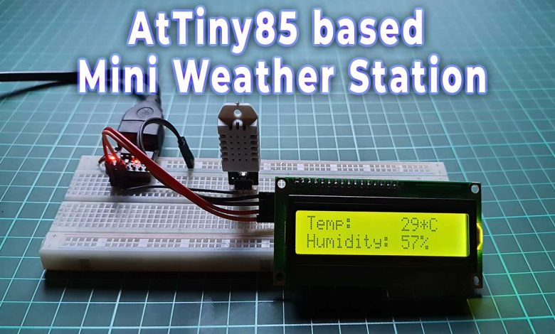
If you are willing to embed a microcontroller into your project but looking for something smaller and cheaper than Arduino. where you don’t require lots of input-output pins or code space then AtTiny85 is perfect for you. So, today we will learn to build a mini weather station using DHT22 sensor and AtTiny85 microcontroller. Here we will build two versions of this weather station. In the first version, we will use DHT22, 16×2 I2C LCD Display, and AtTiny85. Whereas in the second build we will use a 0.96-inch OLED Display (SSD1306), DHT22 Temperature and Humidity sensor, and AtTiny85 microcontroller.
Overview: Mini Weather Station using AtTiny85
Due to global warming weather is now unpredictable. Weather can change our moods, feelings, and mind too. Because unexpected weather sometimes can ruin our plans and schedules. Temperature & Humidity monitoring system is very important for farmers. This type of small device can help to keep an eye on the growing crops. Thus, this can help in the field of agriculture.
So to predict the weather we require a weather station. It is a basic device that can be useful for weather observation and data collection. Therefore we are building a basic mini weather station with DHT22 and AtTiny85. For Monitoring Temperature and Humidity data, we can use either a 16×2 I2C LCD Display or a 0.96-inch SSD1306 OLED Display.
Working of AtTiny85 based Mini Weather Station
In this project, we will connect the DHT22 Temperature and Humidity sensor to the Digispark Attiny85. From the Digital pin of the DHT sensor, we get the temperature and Humidity value which is then sent to a 16×2 LCD Display or 0.96-inch OLED Display via I2C pins (SCL and SDA) So, here AtTiny85 microcontroller reads the data from the DHT sensor using dht library then sends those data to the display for a monitoring system.
We can further add a buzzer to make a temperature alert system. But, in our project we are using a minimal number of pins P0 to P2, leaving pins P3 to P5 open. So that we can easily plug in the USB cable to upload the new program code without disconnecting anything. Pin 5 is mainly a reset input that sometimes works without issue as an Input/Output pin. But it doesn’t always work due to low voltage and current capabilities.
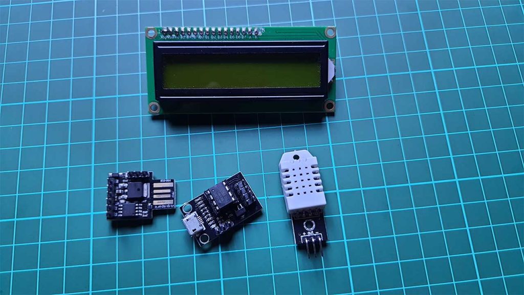
Components Required
Following are the components required to make this Tiny weather station. You can easily buy the components from the amazon link provided below.
| S.N | Components Name | Quantity | |
|---|---|---|---|
| 1 | DigiSpark Attiny85 Board | 1 | https://amzn.to/3CNtfOZ |
| 2 | DHT22 Sensor | 1 | https://amzn.to/3havYuI |
| 3 | 0.96 inch OLED Dispaly | 1 | https://amzn.to/3fBInra |
| 4 | 16x2 I2C LCD Display | 1 | https://amzn.to/3FLZtgv |
| 5 | Jumper Wires | 5 | https://amzn.to/3MKjju6 |
| 6 | Breadboard | 1 | https://amzn.to/3eJiEMW |
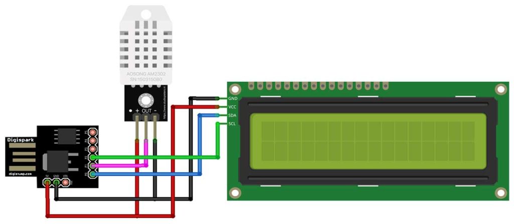
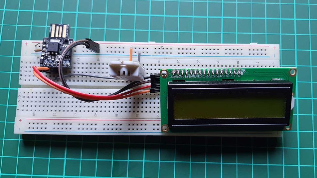
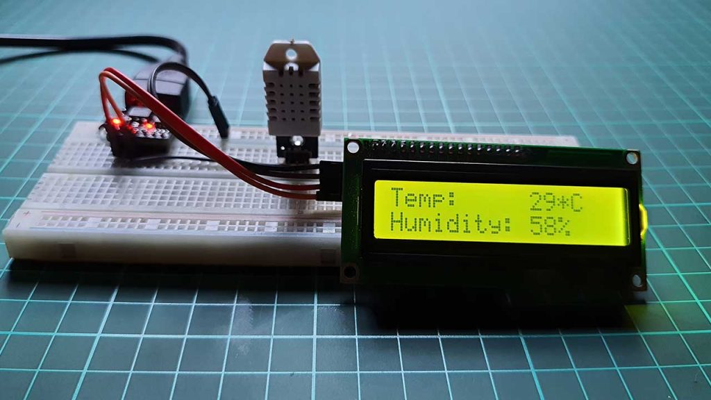
Interfacing DHT22 Sensor & 16×2 I2C LCD Display with AtTiny85
Now. Let’s interface DHT22, and I2C Display, with Digispark Attiny85. Connect the Ground pin of the DHT22 sensor, and Display to the GND pin of Attiny85. Now, connect the VCC pin of the DHT22 sensor to the 5 Volt pin. Similarly, DHT22 sensor output pin to the P1 pin of Attiny85. Lastly, connect the Display SDA pin to P0 and SCL pin to the P2 pin of Digispark Attiny85. You can follow the circuit diagram and table below to assemble the circuit.
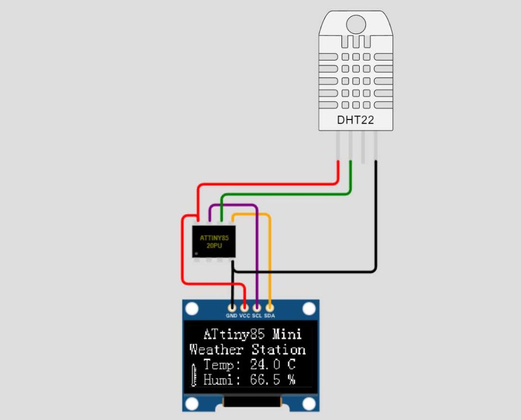
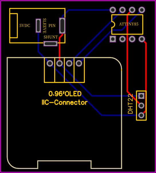
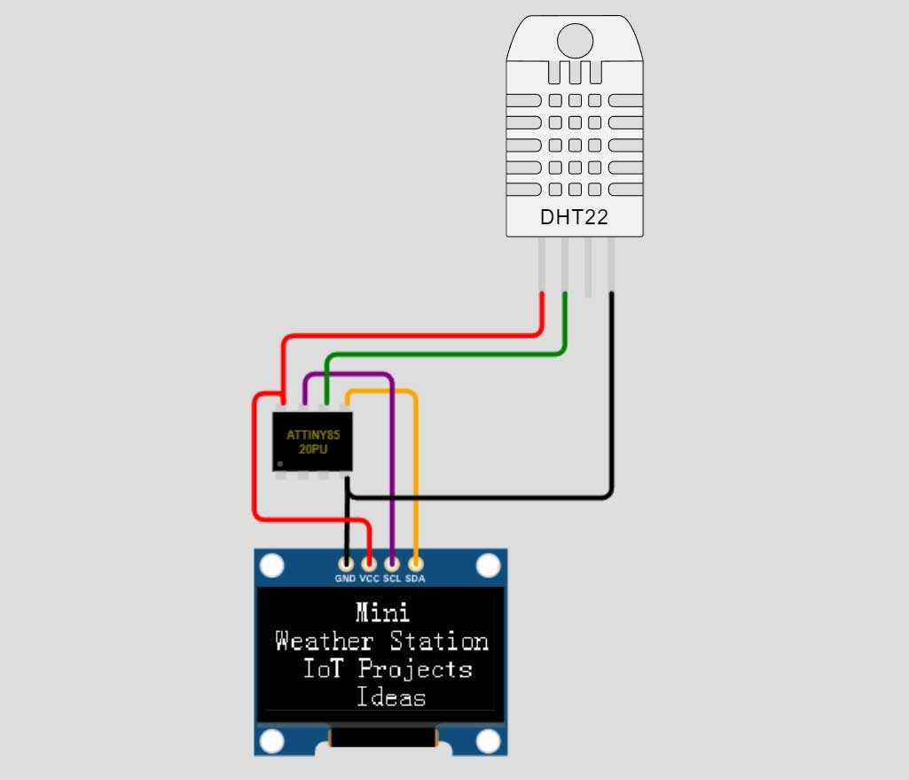
Interfacing 0.96″ I2C OLED Display & DHT22 Sensor with AtTiny85
There is no difference in the circuit assembly. The following connections are needed for OLED Version:
- Pin 0 – Connect to LCD I2C (SDA)
- Pin 1 – Connect to DH22 sensor output pin
- Pin 2 – Connect to LCD I2C (SCL)
- Pins 3 – 5 are not used.
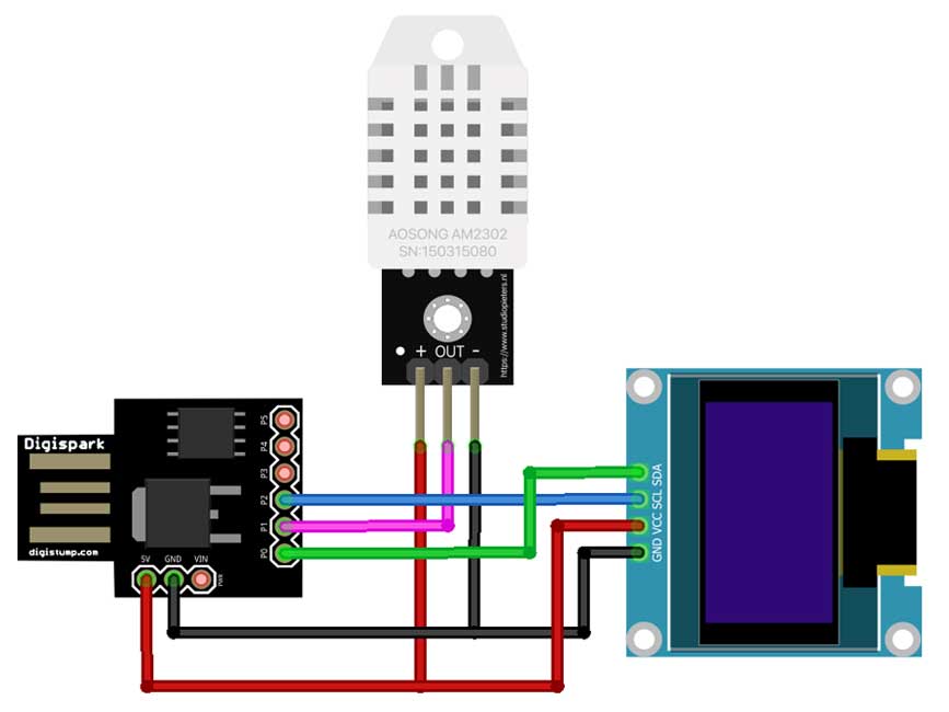
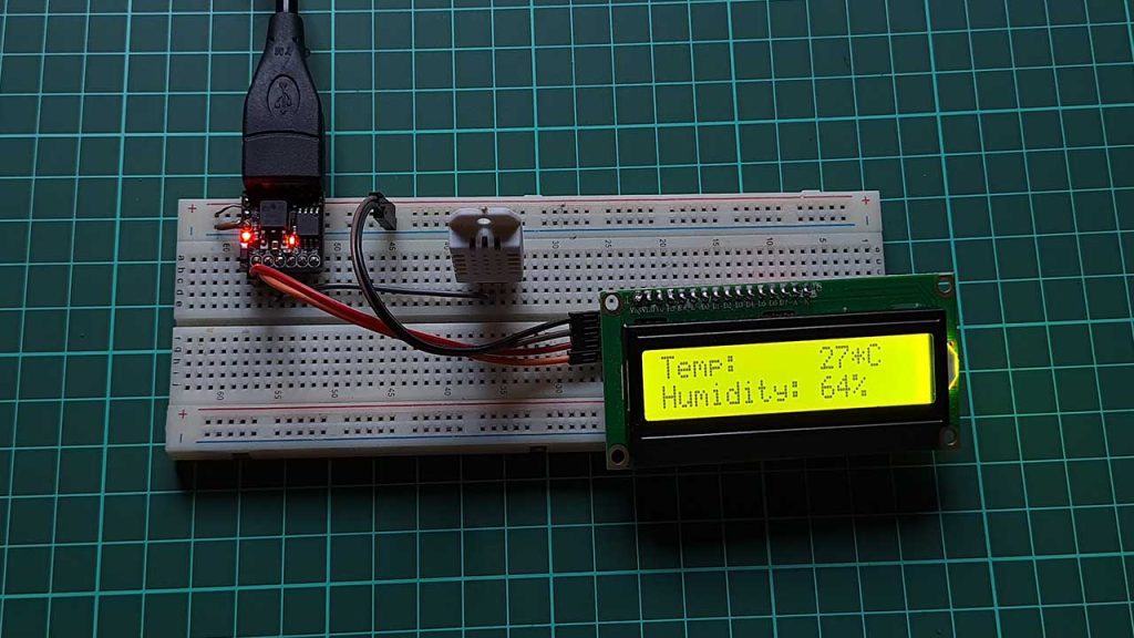
In our setup here, we are providing a 5V power supply through a USB port to power the LCD display, DH22 sensor, and the ATtiny85 module.
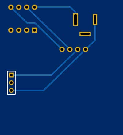
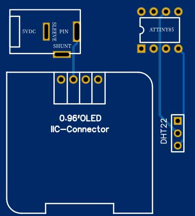
Ordering Custom PCB Online
Do you want professional PCBs like this one that look so good? then use the services of PCBWay.com
Because PCBWay is a one-stop solution for all your PCB needs like PCB prototyping, SMD stencils, PCB assembly, 3D printing, etc. You can also order CNC custom parts from here. Recently, they have moved to a new factory and offer you up to 20% discount on 4-layer PCBs and 6-layer PCBs.

So, get your first prototype PCB ready from pcbway.com, the Gerber file link is provided below.
- Just click on the PCB Instant quote tab.
- Then click on Quick Order PCB.
- Now Upload your Gerber file
- Select your preferred shipping method
- Place your order.
Program/Source code
This Mini Weather Station using DHT22 & AtTiny85 has two different versions. So both will have different program codes. The LCD display uses LiquidCrystal_I2C.h library whereas the OLED Display uses Tiny4KOLED.h These libraries are modified to work with the ATiny85. If you are getting errors because the program is not finding the correct library to use, simply copy the LiquidCrystal_I2C.h and LiquidCrystal_I2C.cpp files from the Digistump download location to the same folder as the ATtiny85 sketch. The standard DHT.h library for reading the DH22 sensor works fine with the AtTiny85.
Mini Weather Station LCD Version Program code
This is the final program code for the mini weather station using AtTiny85, DHT22, and 16×2 I2C Display. Copy this code and paste it into your Arduino IDE.
/*
  ATTiny85 Weather Station
  Uses a 16x2 LCD with I2C interface and DHT22 or DHT11 humidity sensor
*/
#include <USI_TWI_Master.h>
#include <TinyWireM.h>                  // I2C Master lib for ATTinys which use USI - comment this out to use with standard arduinos
#include <LiquidCrystal_I2C.h>
#include <TinyDHT.h>               // Include the DHT library for humidity sensor

#define DHTTYPE DHT22
#define TEMPTYPE 0        // Use Fahrenheit (0 for celsius)
#define DHTPIN 1
DHT dht(DHTPIN, DHTTYPE);  // Define Temp Sensor

LiquidCrystal_I2C lcd(0x27,16,2);  // set I2C address, 16 chars, 2 line Display
//===============================================================================
//===============================================================================
void setup() {
  TinyWireM.begin();   // initialize I2C lib
  dht.begin();  // Initialize DHT Teperature Sensor
  lcd.init();                           // initialize the lcd
  lcd.backlight();                      // Turn on the backlight
  lcd.setCursor(0,0);     //Set cursor to char 0, line 0
  lcd.print("Temp:");
  lcd.setCursor(0,1);     //Move cursor to char 0, line 1
  lcd.print("Humidity:");
}
//===============================================================================
//===============================================================================
void loop() {
  int8_t h = dht.readHumidity();               // Read humidity
  int16_t t = dht.readTemperature(TEMPTYPE);   // read temperature

  lcd.setCursor(10,0);
  lcd.print(t); lcd.print("*C");
  lcd.setCursor(10,1);
  lcd.print(h); lcd.print("%");
  delay(2000);                  // DH22 requires 2 Sec delay between reads
}
Mini Weather Station OLED Version Program code
This is the final program code for the mini weather station using AtTiny85, DHT22, and 0.96-inch I2C OLED Display. Copy this code and paste it into your Arduino IDE.
/*
Mini weather station using AtTiny85
*/

#include <dht.h>
#include <TinyWireM.h>
#include <Tiny4kOLED.h>

#define DHT22_PIN PB1

const unsigned char  img_thermometer[] PROGMEM = {
  0x00, 0xfe, 0x03, 0xfe, 0x50,
  0x00, 0xff, 0x00, 0xff, 0x55,
  0x60, 0x9f, 0x80, 0x9f, 0x65,
};

dht DHT;

void splash() {
  oled.clear();
  oled.setCursor(50, 0);
  oled.print(F("Mini"));

  oled.setCursor(5, 2);
  oled.print(F("Weather Station"));

  oled.setCursor(20, 4);
  oled.print(F("IoT Projects"));

  oled.setCursor(50, 6);
  oled.print(F("Ideas"));
}

void prepareDisplay() {
  unsigned int i, k;
  unsigned char ch[5];

  oled.clear();
  oled.begin();

  oled.setCursor(15, 0);
  oled.print(F("ATtiny85 Mini"));
  oled.setCursor(1, 2);
  oled.print(F("Weather Station"));

  oled.bitmap(2, 5, 7, 8, img_thermometer);
  oled.setCursor(15, 4);
  oled.print(F("Temp: 32.0 °C"));
  oled.setCursor(15, 6);
  oled.print(F("Humi: 67.0 %"));
}

float getTemperature() {
  return DHT.temperature;
}

float getHumidity() {
  return DHT.humidity;
}

void setup() {
  pinMode(DHT22_PIN, INPUT);

  oled.begin(128, 64, sizeof(tiny4koled_init_128x64br), tiny4koled_init_128x64br);

  // Two fonts are supplied with this library, FONT8X16 and FONT6X8
  oled.setFont(FONT8X16);

  // To clear all the memory
  oled.clear();
  oled.on();

  splash();

  delay(3000);
  prepareDisplay();
}

void loop() {
  static long startTime = 0;
  long currentTime;

  DHT.read22(DHT22_PIN);

  // Get current time
  currentTime = millis();

  // Checks 1 second passed
  if ((currentTime - startTime) > 1000) {
    startTime = currentTime;

    // Update temperature
    float temperature = getTemperature();

    // Set cursor
    oled.setCursor(15, 4);
    oled.print("Temp: ");
    // Print to display
    oled.print(temperature, 1);
    oled.print(" °C  ");

    // Update humidity
    float humidity = getHumidity();

    // Set cursor
    oled.setCursor(15, 6);
    oled.print("Humi: ");
    // Print to display
    oled.print(humidity, 1);
    oled.print(" %  ");

    oled.bitmap(2, 5, 7, 8, img_thermometer);
  }
}
Uploading code & testing project:
Before uploading the code, make sure you have set up your Arduino IDE for the Digispark Attiny85 board.
Now copy the program code provided for the Mini Weather Station System using AtTiny85 from above
Select “Digispark (Default-16.5Mhz) Board from Tools Menu. Also, select the programmer as “Micronucleus” and choose its COM port.
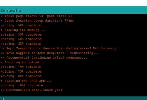
Finally, press the upload button after compiling the code, and connect your Digispark Attiny85 board within 60 seconds. Wait for “Micronucleus done. Thank you!” Message for the successful upload of the program.
Now it’s time to test the weather monitoring System using the AtTiny85 project.
Gently provide some external heat to the dht22 sensor and you can see the result on the Display.

Online Project Simulation on Wokwi.com You can also get the project simulation link below.
Conclusion
This is a very useful project and has a wide range of applications. If you like this tutorial, then share this project with your friends. If you Need help? Then Comment down below.