Temperature Controlled Home Automation using Arduino
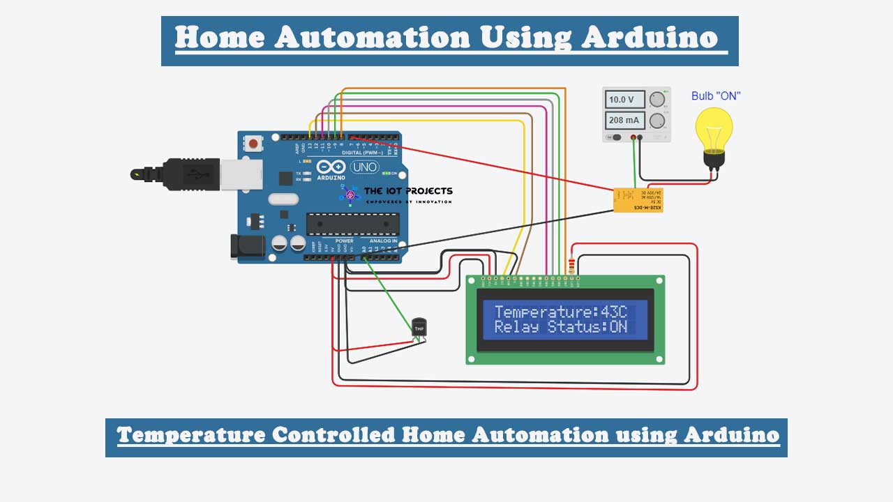
The main objective of this project is to build Temperature Controlled Home Automation using Arduino. The system build will be able to control your AC Home Appliances like Fan, Heater, Cooler, or even light bulbs. Suppose you are sitting in a room and you’re feeling hot. Now you want your cooler or fan to be “ON” automatically, and then “OFF” when room temperature is back to normal. If you are searching for such a project then you’re at the right place. This project will help you to control your home appliances automatically based on your room temperature.
Nowadays, technology is advancing and houses are getting smarter. Modern houses are usually shifting from conventional switches to some kind of centralized control system with remote control and switches. As we all know, conventional switches located in different location of the house makes it difficult in accessing them. Users need to go near them to operate. It is more difficult for elderly folk and handicapped people.
In this case, remote control switches are also difficult to operate. Suppose someone among the family member used a remote controller and kept it somewhere else by mistake. Now you need to waste a lot of time searching for it. furthermore, they need separate batteries to operate, and frequently changing them will decrease your pocket money too. Hence, a temperature-controlled home automation system using Arduino provides the most modern solution.
Components required
- Arduino UNO
- 5V Relay Module
- 16*2 LCD display
- TMP36 Temperature Sensor
- Light Bulb/Fan/Cooler
- Connecting wires
Firstly, we will be using TMP36 (Temperature Sensor) to read the temperature. Secondly, we will attach an AC Home appliance with Relay. Finally, a 16×2 LCD Display will be used to display temperature and appliances status. And hence a temperature-controlled home automation system using Arduino is built.
Video Demonstration
Working of Temperature controlled Home Automation System
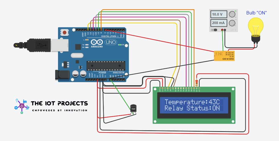
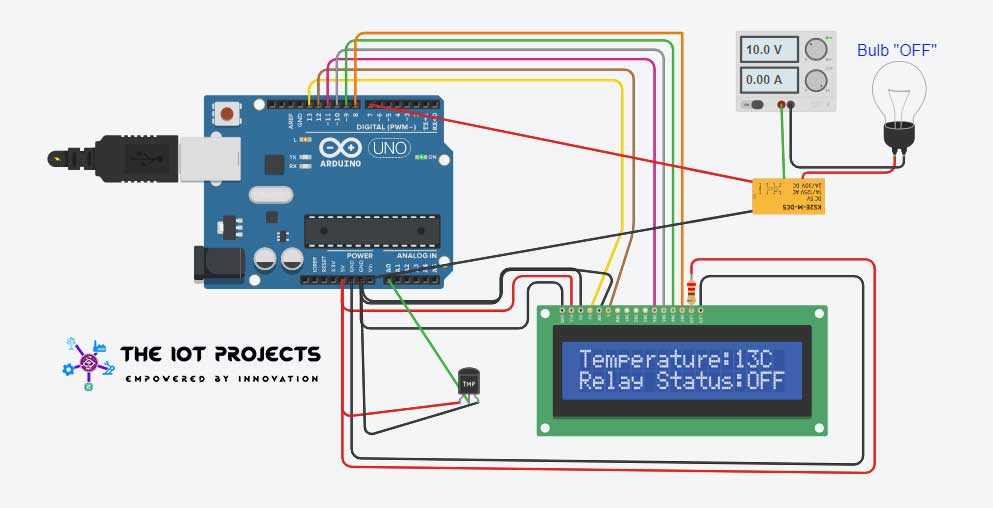
This Temperature based Home Automation System consists of components like the Arduino UNO board, 16×2 LCD display, Relay, and Temperature Sensor. The whole system depends on the Relay and TMP36, as the temperature increases the relay will be turned “ON” and if the temperature decreased below the preset value then Relay will be turned “OFF”. Hence, the home appliance attached to the Relay will also turn NO and OFF accordingly. Here we have used a Light bulb as an AC appliance for demonstration purposes. The entire relay triggering and setting temperature value is performed by the Arduino board. The programmed Arduino UNO board provides details on the LCD screen when the temperature get changes.
Schematic Diagram
The circuit diagram of the Arduino-based home automation system is very easy to understand. Actually, here we are controlling Relay using Arduino and TMP36 sensor for simple automation. You can easily assemble the circuit diagram as below figure. However, the following table will help you to interface all the components to the Arduino.
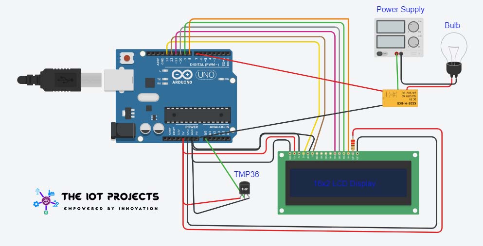
| 16×2 LCD Pins | Arduino Pins |
|---|---|
| VSS | GND |
| VDD | 5v |
| Vo | GND |
| RS | 13 |
| RW | GND |
| EN | 12 |
| D4 | 11 |
| D5 | 10 |
| D6 | 9 |
| D7 | 8 |
| A | 5V |
| K | GND |
| Temperature (TMP36) Sensor | Arduino Pins |
| VCC | 5V |
| GND | GND |
| Center Pin | A0 |
| 5V Relay Module | Arduino Pins |
| VCC | 5V |
| GND | GND |
| Center Pin | D7 |
Program sketch/code
The Complete Arduino Code for Temperature Controlled Home Automation System is provided at the end of this programming session. Here we have explained how the code is written.
The LCD header file and it’s pins are assigned.
#include <LiquidCrystal.h>
LiquidCrystal lcd(13, 12, 11, 10, 9, 8);
The output pin of (TMP36) Temperature sensor is defined.
int tempin = A0;The following Variables are declared.
int temp;
int cel;
int tempmin = 69.632;
Pin for relay is defined.
int relay = 7;In Void Setup() PinMode function is used for temperature(TMP36) sensor as INPUT. Then start a serial monitor at the baud rate of 9600. 16×2 LCD is initiated. Again PinMode Function is declared for the relay as OUTPUT.
void setup() {
  pinMode(tempin, INPUT);
  Serial.begin(9600);
  lcd.begin(16, 2);
  pinMode(relay, OUTPUT);
Here we read the temperature through analog pin and convert it to degree Celsius. And display the current temperature on LCD Screen with current relay status as well.
void loop() {
  temp = analogRead(tempin);
  cel = temp * 0.48828125;
  Serial.print(cel);
  Serial.println();
  if (tempmin < temp) {
    lcd.setCursor(0, 1);// move cursor to next line
    lcd.print("Relay Status:");
    lcd.print("ON"); // display the temperature
    digitalWrite(relay, LOW);
  }
Triggering relay to OFF.
 else {
    lcd.setCursor(0, 1);// move cursor to next line
    lcd.print("Relay Status:");
    lcd.print("OFF"); // display the temperature
    digitalWrite(relay, HIGH);
  }
Display the temperature value and clear the screen with the delay of 3 seconds.
 lcd.setCursor(0, 0);
  lcd.print("Temperature:");
  lcd.print(cel); // display the temperature
  lcd.print("C ");
  delay(3000);
  lcd.clear();

}
Temperature based Home Automation using Arduino Code
#include <LiquidCrystal.h>
LiquidCrystal lcd(13, 12, 11, 10, 9, 8);
int tempin = A0; // the output pin of TMP36
int temp;
int cel;
int tempmin = 69.632;
int relay = 7;
void setup() {
  pinMode(tempin, INPUT);
  Serial.begin(9600);
  lcd.begin(16, 2);
  pinMode(relay, OUTPUT);

}

void loop() {
  temp = analogRead(tempin);
  cel = temp * 0.48828125;
  Serial.print(cel);
  Serial.println();
  if (tempmin < temp) {
    lcd.setCursor(0, 1);// move cursor to next line
    lcd.print("Relay Status:");
    lcd.print("ON"); // display the temperature
    digitalWrite(relay, LOW);
  }


  else {
    lcd.setCursor(0, 1);// move cursor to next line
    lcd.print("Relay Status:");
    lcd.print("OFF"); // display the temperature
    digitalWrite(relay, HIGH);
  }


  lcd.setCursor(0, 0);
  lcd.print("Temperature:");
  lcd.print(cel); // display the temperature
  lcd.print("C ");
  delay(3000);
  lcd.clear();

}
We have few more Arduino based projects that you may like:
- DIY Mobile Phone using GSM Module & Arduino with Nextion Display
- Capacitive Soil Moisture Sensor with OLED Display & Arduino
- Interfacing Temperature and Humidity Sensor with Arduino
- Simple Weather station using Arduino & BME280 Barometric Pressure Sensor
Now copy this sketch code and paste it on your Arduino IDE. You can make your necessary changes like minimum temperature to trigger your relay. Now Choose your Arduino UNO board and COM Port. Just hit that compile button and upload the code to the Arduino. Enjoy your Modern Temperature Controlled Home Automation using Arduino and TMP36.
Wrapping Up
Finally, I have completed the Smart Home Automatic AC temperature controller Project. I hope you found this project useful! Drop a comment below if you have any queries. I will try to answer all of your questions. Stay Happy! Stay safe

Can I use a solid state relay?
Yes you can use solid state relay.
I liked ur project how to set tempreture what we need
Set the temperature threshold value through blynk app
sir can i replace TMP36 with dht 11 and dht 22
Hello please I want to use 16×4 lcd, what do I do differently?
i am using a GLD 1602IIC does the same code and connection apply?