Welcome to The IoT Projects. In this tutorial, we are going to see a sensor that measures the Temperature and Humidity. We will also interface the DHT-11 Temperature and Humidity Sensor to the Arduino by Programming it. Hence today’s topic is all about Interfacing Temperature and Humidity Sensor with Arduino.
Components Required
- Arduino UNO
- DHT-11 Temperature and Humidity Sensor
- Jumper wires
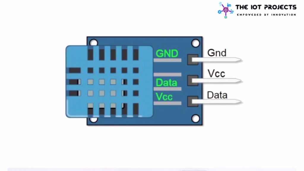
DHT-11 Pinouts
This is the sensor that we are going to use in this tutorial. Its name is DHT-11, It can give the temperature and Humidity using one wire called Data. The power supply pin(VCC) can be connected to the range of 3.5 to 5 volts.
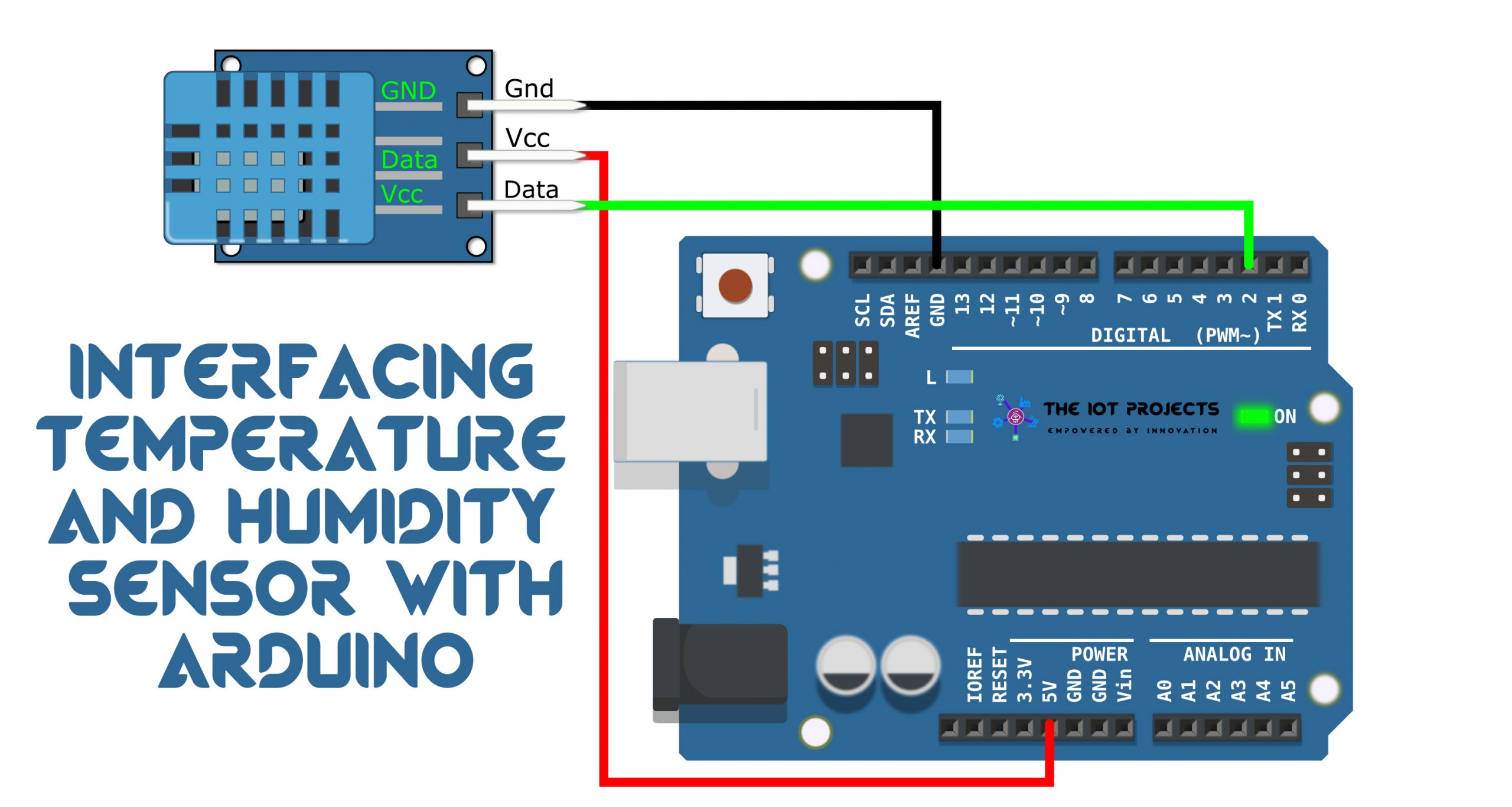
Schematic of DHT-11 and Arduino
Actually, the connection in this tutorial is very simple because there are only three wires that are VCC, GND, and Data.
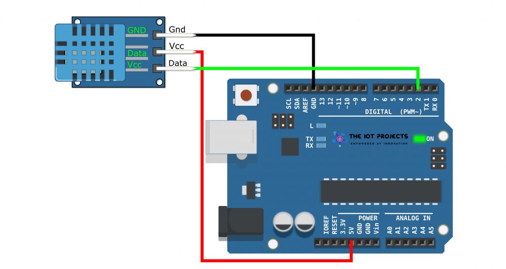
- Connect the Ground(GND) of the Arduino board to the GND pin of the Arduino
- Now, connect 5 volts to the VCC pin.
- Finally, connect the pin number 2 of the Arduino board to the Data Pin of the DHT-11 Sensor.
Programming Sketch/Codes
Now, let’s program the Arduino board using this sketch. But, before that let me explain these few lines of codes. So that it will be easier to understand the codes.
As we are using the DHT library. The header file has to be included. So open the tools menu and upload the library file.
#include <SimpleDHT.h>A variable called “pinDHT11” is declared with a value 2 as the pin of the Arduino board where the Data pin is connected to.
// for DHT11,
//      VCC: 5V or 3V
//      GND: GND
//      DATA: 2
int pinDHT11 = 2;
The next variable called “dht11” of type “simpleDHT11” is declared to handle the communication with the sensor.
SimpleDHT11 dht11;Inside the function setup() the serial interface is initialized with 9600 as the baud rate.
void setup() {
  Serial.begin(9600);
}
Every time that we send the information to the computer. we will start with a separation line and the text “Sample DHT11…“
Serial.println("Sample DHT11...");Here, we have declared 3 variables, an array of 40 elements called “data” that will hold the raw data from the sensor. And the variables “temperature” and “Humidity” for the values of measured magnitudes.
 // read with raw sample data.
  byte temperature = 0;
  byte humidity = 0;
  byte data[40] = {0};
The function “read” is called with the pin “pinDHT11” and a reference to the variable “Temperature“, “Humidity” and the “Data” array. How these variables are going to be populated inside the function. Basically, the passing has to be done by reference (&). The data array is already a reference and does not need &. The “read” function will return a 0. If everything went well.
if (dht11.read(pinDHT11, &temperature, &humidity, data)) {The 40 bits received from the sensor are sent to the PC.
Serial.print("Sample RAW Bits: ");
  for (int i = 0; i < 40; i++) {
    Serial.print((int)data[i]);
    if (i > 0 && ((i + 1) % 4) == 0) {
      Serial.print(' ');
    }
Finally, the Temperature in (Celsius) and Humidity in (Percentage) are sent.
Serial.print((int)temperature); Serial.print(" *C, ");
  Serial.print((int)humidity); Serial.println(" %");
Under the loop function, we added a 1-sec delay. Therefore, we sent the data every second.
delay(1000);Final Sketch/Codes
//https://iotprojectsideas.com/
//2020.2.29

#include <SimpleDHT.h>

// for DHT11,
//      VCC: 5V or 3V
//      GND: GND
//      DATA: 2
int pinDHT11 = 2;
SimpleDHT11 dht11;

void setup() {
  Serial.begin(9600);
}

void loop() {
  // start working...
  Serial.println("=================================");
  Serial.println("Sample DHT11...");

  // read with raw sample data.
  byte temperature = 0;
  byte humidity = 0;
  byte data[40] = {0};
  if (dht11.read(pinDHT11, &temperature, &humidity, data)) {
    Serial.print("Read DHT11 failed");
    return;
  }

  Serial.print("Sample RAW Bits: ");
  for (int i = 0; i < 40; i++) {
    Serial.print((int)data[i]);
    if (i > 0 && ((i + 1) % 4) == 0) {
      Serial.print(' ');
    }
  }
  Serial.println("");

  Serial.print("Sample OK: ");
  Serial.print((int)temperature); Serial.print(" *C, ");
  Serial.print((int)humidity); Serial.println(" %");

  // DHT11 sampling rate is 1HZ.
  delay(1000);
}
Video Tutorials
Conclusion
Finally, we have completed Interfacing Temperature and Humidity Sensor with Arduino. Now, you can see the temperature and Humidity from the Serial Monitor. We hope you found this project useful! Drop a comment below if you have any doubts or queries. We’ll do our best to answer your questions.