Arduino Intruder Security Alert System
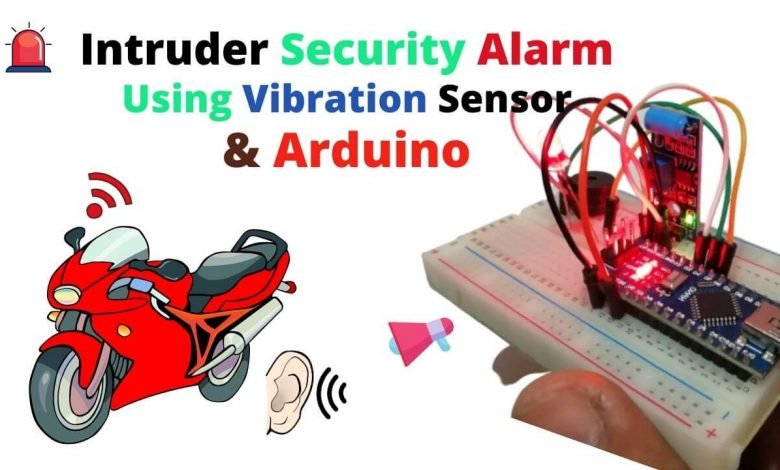
Bike Security System Using Arduino & Vibration Sensor
Introduction
I will show you how to make an Arduino Intruder Security Alert System using Vibration Sensor in today’s tutorial. You can implement this system in your vehicles so as any intruder or someone tries to sit on your bike, it will create some vibration and the alarm will start buzzing with flashing led.
Working of Intruder security Alarm
In this project, we will connect the vibration sensor to the Arduino. When there is no vibration, the output of the vibration sensor is 0 (low voltage), Else the output is 1 (High Voltage). If Arduino gets 1 output from the vibration sensor, it will turn on Buzzer and LED.
Components Required
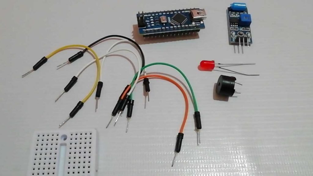
So let’s get started making Arduino Intruder Security Alert System using Vibration Sensor. To make this system more compact, I am using Arduino Nano. Following are the lists of all the components that are required for building this project.
| S.N | Components Name | Description | Quantity | |
|---|---|---|---|---|
| 1 | Arduino Nano | Arduino Nano R3 | 1 | https://amzn.to/3swvBuO |
| 2 | Vibration Sensor | Vibration Sensor | 1 | https://amzn.to/3v2Addj |
| 3 | Buzzer | Small 2 pin Buzzer | 1 | https://amzn.to/2OKdkvv |
| 4 | LED | 5 Mm RED LED | 1 | https://amzn.to/3cwvtoG |
| 5 | Jumper Wires | Jumper Cables breadboard friendly | 10 | https://amzn.to/2JWSR44 |
| 6 | Breadboard | Mini Breadboard | 1 | https://amzn.to/2NP2UKL |
Circuit Diagram: Arduino Intruder Security Alert System
Now. let’s learn to interface Vibration sensors, Buzzer, & LED with Arduino.
I assemble the circuit in a breadboard, but you can order a custom PCB from NextPCB. Now you can visit https://www.nextpcb.com/ and order the PCB. NextPCB is one of the biggest PCB manufacturer companies in China. They offer very good quality PCB at a reasonable price. NextPCB new customers also receive a $100 Coupon as a signup bonus.
The circuit connection is fairly simple. Connect the Ground pin of the Vibration sensor, buzzer, and LED to the GND pin of Arduino. Now, connect the VCC pin of the vibration sensor to the 5Volt pin. Similarly, D0 (signal) pin to D3 pin of Arduino. Lastly, connect the buzzer positive pin to D4 and the LED positive pin to the D5 pin of Arduino. You can follow the schematics and table below to assemble the circuit.
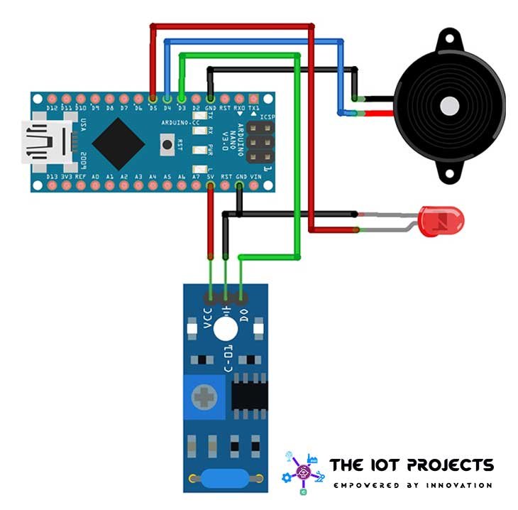
| Vibration Sensor | Arduino |
| VCC | 5V |
| GND | GND |
| D0 | Digital pin 3 |
| Buzzer | Arduino |
| Positive | Digital pin 4 |
| GND | GND |
| LED | Arduino |
| Positive | Digital pin 5 |
| Negative | GND |
Similar Projects:
- IoT based Silent Intruder Alarm using Arduino
- Fire Security System using Arduino & Flame Sensor
- ESP8266 based IoT Health Care Panic Alarm for Elderly Folks
- Password Security Lock System Using Arduino & Keypad
Program code: Arduino Intruder Security Alert System
I will explain every step of the program code to help you understand and modify it according to your requirements. First, we defined the variable “Buzz” for the buzzer, “vs” for vibration sensor, and “LED” for Red LED with their interfaced pin with Arduino.
int Buzz = 4; //Buzzer
int LED = 5;  //LED
int vs =3; // vibration sensor
int i=0;
In a void setup, we have defined the pinMode function for all the components
void setup(){
  pinMode(Buzz, OUTPUT);
  pinMode(LED, OUTPUT);
  pinMode(vs, INPUT);
}
Here, in a loop, the program reads the data from the vibration sensor, if there a vibration the result is High. In this condition, Buzzer and LED are turned ON.
void loop(){
int vib = digitalRead(vs);
  if(vib == HIGH)
  {
    for(i=0;i<10;i++)
    {
    digitalWrite(Buzz, HIGH);
    digitalWrite(LED, HIGH);
    delay(500);
    digitalWrite(Buzz, LOW);
    digitalWrite(LED, LOW);
    delay(100);
  }
  }
Else the buzzer and LED remains in an OFF state
else{
    digitalWrite(Buzz, LOW);
    digitalWrite(LED, LOW);
  }
}
Intruder Security Alert Final Program code
This is the final program code for Arduino Intruder Security Alert System using Vibration Sensor. Copy this code and paste it into your Arduino IDE.
//The IoT Projects: https://theiotprojects.com
//Arduino Intruder Security Alert System using Vibration Sensor

int Buzz = 4; //Buzzer
int LED = 5;  //LED
int vs =3; // vibration sensor
int i=0;
void setup(){
  pinMode(Buzz, OUTPUT);
  pinMode(LED, OUTPUT);
  pinMode(vs, INPUT);
}
void loop(){
int vib = digitalRead(vs);
  if(vib == HIGH)
  {
    for(i=0;i<10;i++)
    {
    digitalWrite(Buzz, HIGH);
    digitalWrite(LED, HIGH);
    delay(500);
    digitalWrite(Buzz, LOW);
    digitalWrite(LED, LOW);
    delay(100);
  }
  }
  else{
    digitalWrite(Buzz, LOW);
    digitalWrite(LED, LOW);
  }
}
Uploading code & testing project:
Now copy the program code provided for the Arduino Intruder Security Alert System using vibration sensor from above. Select “Arduino Nano” Board from Tools Menu. Also, select its COM port.
Compile the code and click on the upload button. You will see the “Upload Done” message after a successful upload of the program.
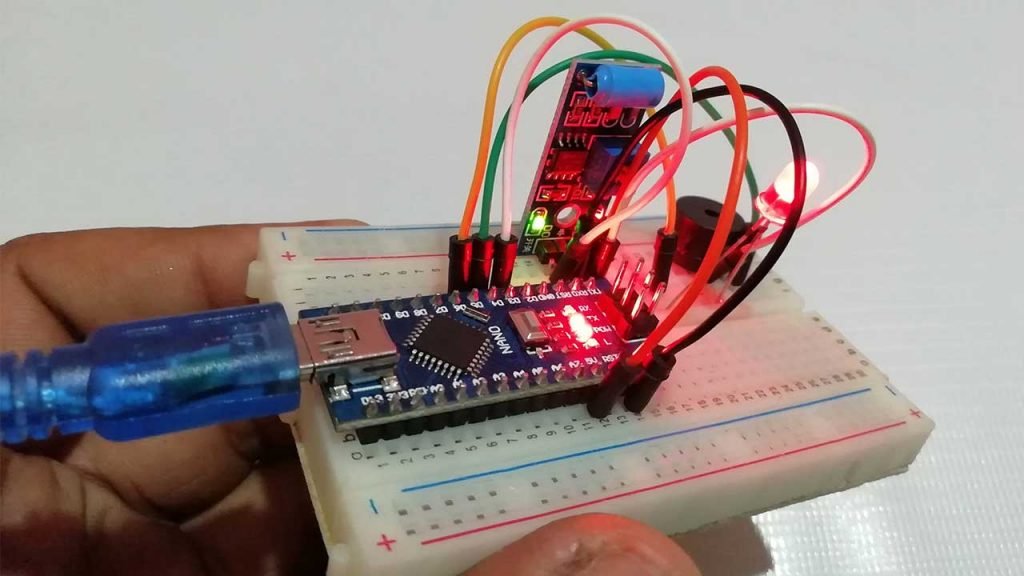
Now it’s time to test the Arduino Intruder Security Alert System using Vibration Sensor project. Gently shake the vibration sensor and you will start getting feedback from the buzzer and LED.
Conclusion
So, that’s all for this Arduino Intruder Security Alert System using a Vibration Sensor. This is a very useful project and has a wide range of applications in the security field. If you like this tutorial, then share this project with your friends. Need help? Comment down below. Wanna make this project more compact? Check this out: Intruder Security Alarm using Vibration Sensor