BMP280 Based IoT Weather Station using ESP8266 & OLED Display
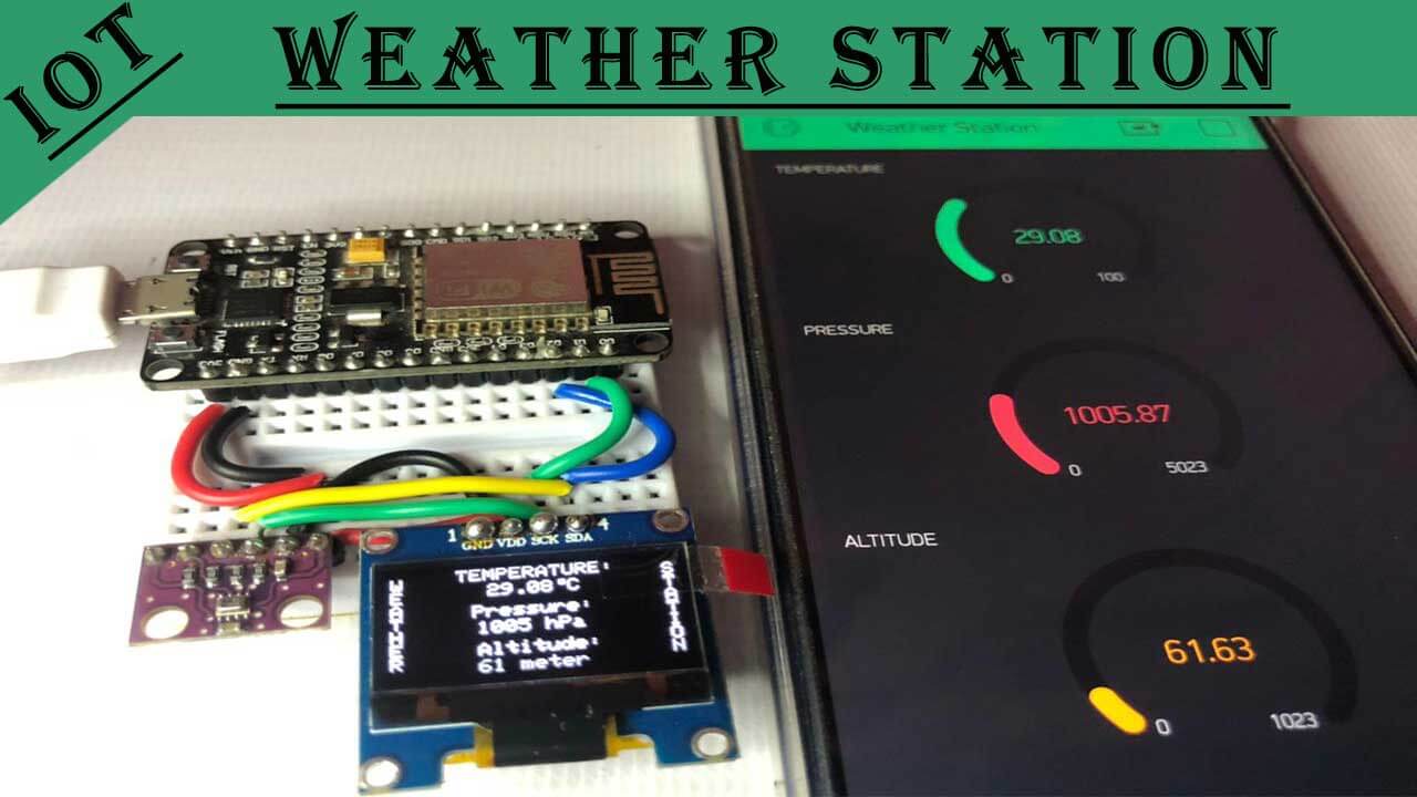
Today in this tutorial, we will learn to interface the BMP280 sensor with the NodeMCU ESP8266 development board, then monitor its parameters like temperature, barometric pressure, and altitude, on the 0.96 inch OLED display and also on the Blynk IoT Platform. This IoT Project provides your NodeMCU ESP8266 board the ability to sense the environment with a BMP280 Barometric Pressure sensor. Overall, we are building ESP8266 & BMP280 based IoT Weather Station.
- Components Required
- Interface BMP280 Sensor & OLED Display with NodeMCU ESP8266
- PCBway for ordering custom PCB
- Configure Blynk App for BMP280 IoT Weather Station
- Programming ESP8266, BMP280 Sensor & OLED Display with Arduino IDE
- Final Program Code For BMP280 based IoT Weather Station
- Demonstration: BMP280 based IoT Weather Station
- Conclusion
Here, the NodeMCU ESP8266 reads the temperature, pressure, and altitude values from the BMP280 sensor and prints them on a 0.96″ (SSD1306) OLED display (128×64 pixel) which can be monitored over the Blynk IoT cloud.
Components Required
The following are the lists of the components that are required for ESP8266 & BMP280 based IoT Weather Station.
| S.N | Components Name | Description | Quantity | |
|---|---|---|---|---|
| 1 | NodeMCU | ESP8266 12E Board | 1 | https://amzn.to/3mTuL95 |
| 2 | BMP280 | Barometric Pressure Sensor | 1 | https://amzn.to/3aNUY5x |
| 3 | 0.96 Inch OLED Display | 0.96 Inch OLED Module 128x64 SSD1306 Driver I2C Serial Self-Luminous Display Board | 1 | https://amzn.to/3pGssa7 |
| 4 | Jumper Wires | Male to Male Jumper Wires | 4 | https://amzn.to/2JWSR44 |
| 5 | Breadboard | Solderless Breadboard MIni | 1 | https://amzn.to/3n33uRT |
Introduction to BMP280 Sensor
The BMP280 Bosch next-generation widely used sensor that measures temperature, barometric pressure, and altitude. Actually, it is pre-calibrated and is relatively simple to use. Because we don’t require any extra components. So we can start measuring its data using the NodeMCU ESP8266 and BMP280 sensor.
At the end of this tutorial, you will also learn how to interface BMP280 or any other I2C device with NodeMCU ESP8266 and display data in the OLED display. Additionally, you will also learn to monitor those Weather Station data from anywhere in the world using the Blynk IoT cloud platform.
BMP280 Sensor Pinout
The following table is the BMP280 sensor Pinout table:

| VCC | Powers the sensor |
| GND | Ground Pin |
| SCL | SCL pin for I2C communicationSCK pin for SPI communication |
| SDA | SDA pin for I2C communicationSDI (MOSI) pin for SPI communication |
| SDO | SDO (MISO) pin for SPI communication |
| CSB | Chip select pin for SPI communication |
BMP280 Sensor Measures
As I already mentioned above, The BMP280 is a Barometric pressure and digital Temperature sensor that can measure:
- Temperature
- Barometric pressure
- Altitude
Accuracy of BMP280 Sensor
The following table shows the Accuracy and operation rangeof the temperature, pressure, and altitude of the BMP280 Sensor:
| Sensor | Accuracy | Operation Range |
| Temperature | +/- 1.0ºC | -40 to 85 ºC |
| Pressure | +/- 1 hPa | 300 to 1100 hPa |
| Altitude | +/- 1 M | 0 – 30,000ft |
Our Previous Weather Station projects
- IoT Weather Station using DHT11 Sensor
- Interface BMP280 Sensor With Arduino
- BME280 Based Mini Weather Station using ESP8266/ESP32
- Simple Weather station using Arduino & BME280 Barometric Pressure Sensor
- ESP8266 & BME280 IoT Weather Station
- BMP280 Based Weather Station using Arduino
Interface BMP280 Sensor & OLED Display with NodeMCU ESP8266
Now, Let’s wire the BMP280 sensor and 0.96″ OLED Display with the NodeMCU development board. The Connections are fairly simple because the OLED and the BMP280 both communicate with the NodeMCU via I2C mode. This means we can connect both modules to the same (I2C) pins on the NodeMCU. Connect the components as shown in the schematics below.
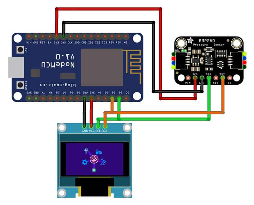
Interface BMP280 Sensor & OLED Display with NodeMCU ESP8266
| BMP280 | NodeMCU ESP8266 |
| Vin | 3.3V |
| GND | GND |
| SCL | D1 |
| SDA | D2 |
| OLED Display | NodeMCU ESP8266 |
| GND | GND |
| VCC | 3.3V |
| SCK | D1 |
| SDA | D2 |
Go through the schematics once more to ensure everything is properly connected.
PCBway for ordering custom PCB
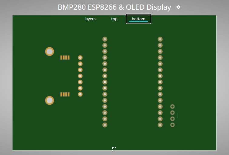
If you don’t want to assemble the circuit on a breadboard and you want Custom PCB for the project, then here is the PCB for you. The PCB Board for the BMP280 Based IoT Weather Station using ESP8266 & OLED Display is designed on EasyEDA. You can simply download the Gerber file from the link below and order the PCB online from PCBWay
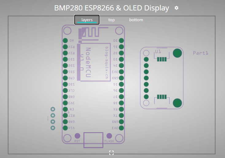
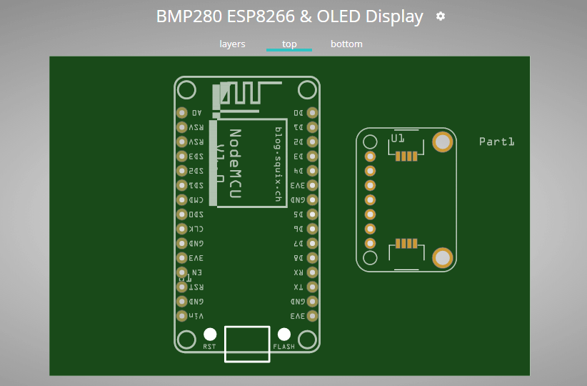
You can also view the PCB through Online Gerber viewer tools by PCBWay. The layers view, top view, and bottom view of the PCB are given below.
Now you can visit the PCBWay official website by clicking here: https://www.pcbway.com/ So you will be directed to the PCBWay website.
PCBWay offers Only $5 for 10 PCBs and a total of $30 dollars for 20 PCBs Assembly. Apart from this PCBWay offers a wide variety of services including Aluminum PCB, Rigid-Flex, Metal Core, Flexible, High Frequency, High-TG, Thick-Copper, HDI, and LED PCBs. The sign-up process takes about a minute and gets $5 as a signup bonus. So, what are you waiting for? get your first prototype order for free.
Configure Blynk App for BMP280 IoT Weather Station
To set up a Blynk IoT App for Wireless Weather Station, you need to first download the app from the Play Store for Android users and the App Store for iOS users. Once the installation is complete, open the app and sign-up using your email address and password.
- Click on create a new project
- Provide the Name of your project as “BMP280 IoT Weather Station”
- Choose NodeMCU Dev Board
- Select connection type as Wi-Fi, then click on Create Button.
- The Blynk authentication token is sent to your email address. (We need it later on programming)
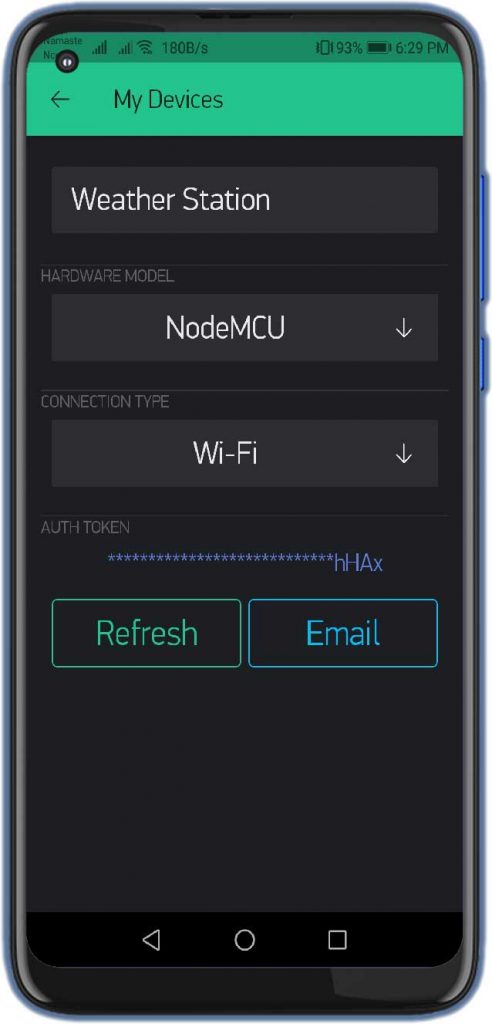
- Now, click on the (+) icon at the top right corner of the screen.
- Search for “Gauges” and add 3 of them to your main screen.
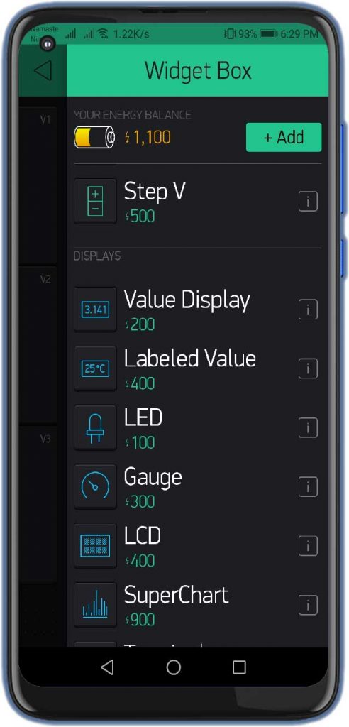
- Click on the First Gauge.
- Name it as “Temperature”
- Set the Input Pin to Virtual Pin V1, Enter input Range & Choose the refresh rate as 1sec.
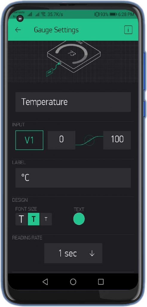
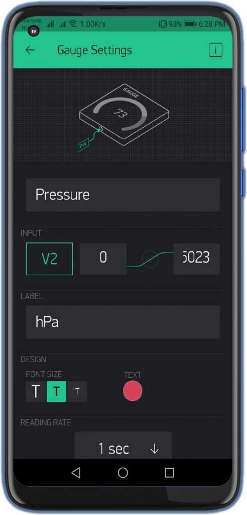
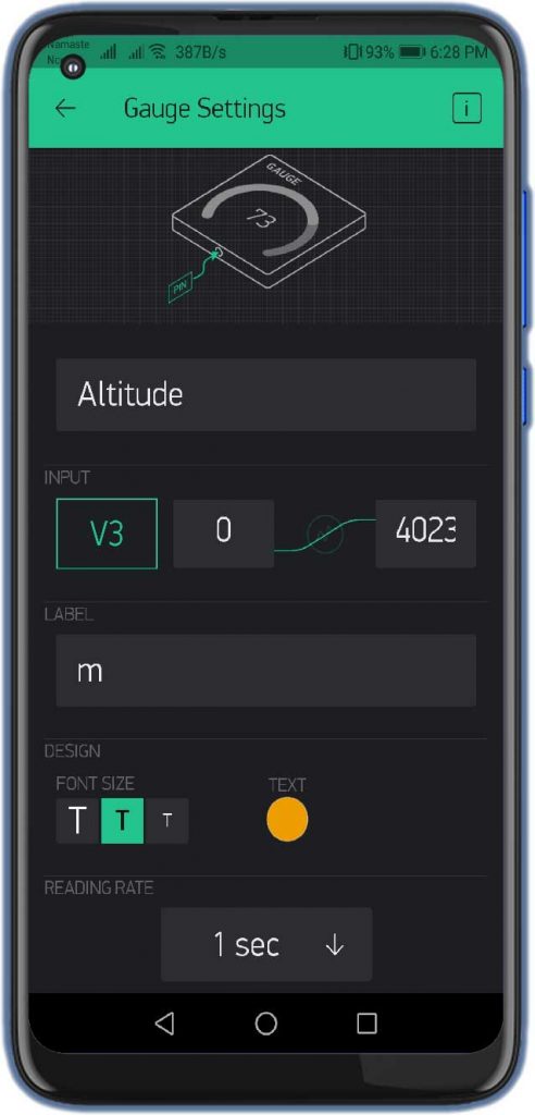
Similarly, do the same for Pressure, and Altitude with the help of the images below.
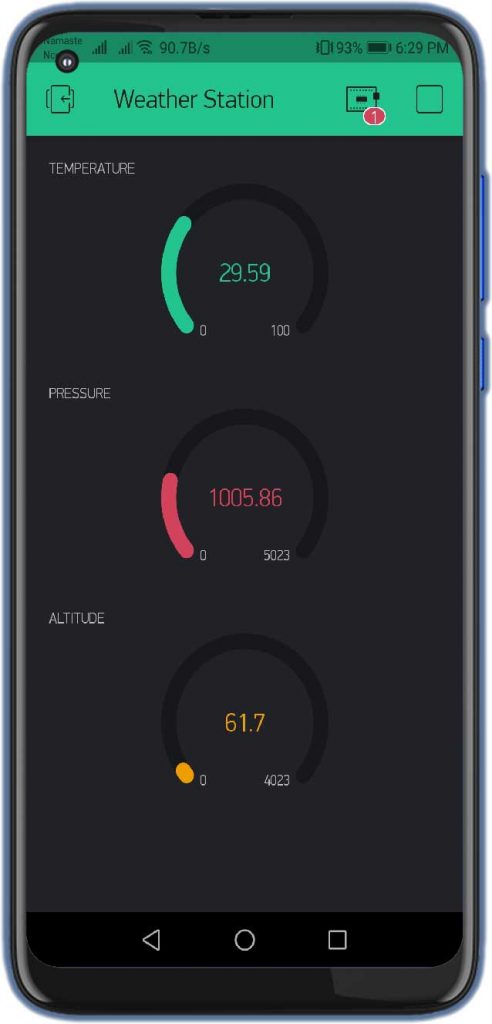
Finally, the Blynk App setup for BMP280 based IoT Wireless weather station using NodeMCU ESP8266 is completed.
Programming ESP8266, BMP280 Sensor & OLED Display with Arduino IDE
To program the ESP8266, OLED & BMP280 sensor with Arduino IDE, we need to install the NodeMCU board Manager add-on and the following libraries.
- Adafruit BMP280 Library
- Adafruit Unified Sensor Library
- Blynk Library
- Adafruit GFX Library
- Adafruit SSD1306 Library
Preparing Arduino IDE For NodeMCU ESP8266
Actually, We’ll program the ESP8266 board using the Arduino IDE. So, make sure you have the ESP8266 add-on installed.
Installing Adafruit BMP280, Unified Sensor, GFX, SSD1306, & Blynk Libraries
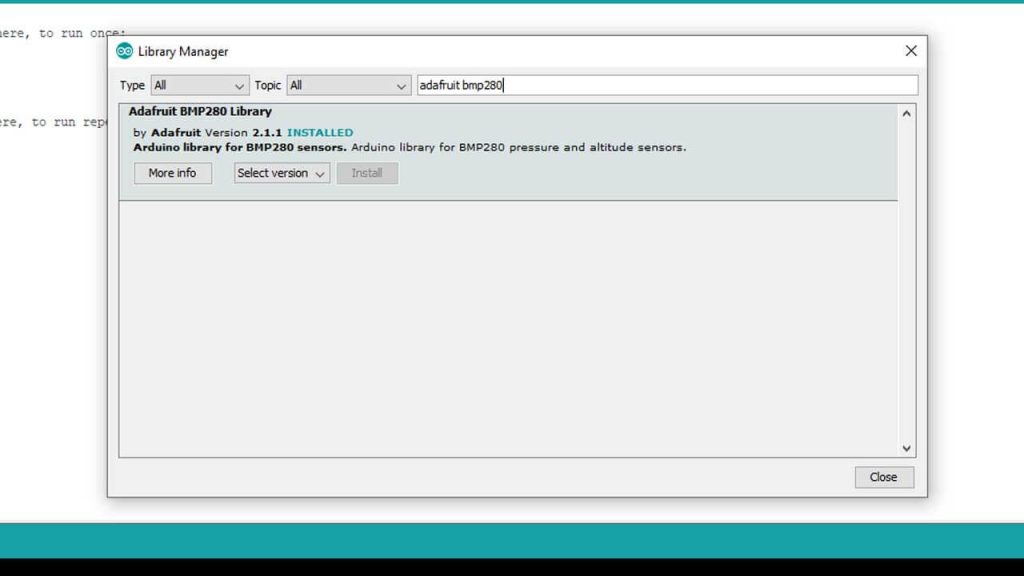
To install the library, navigate to the Sketch > Include Library > Manage Libraries… Wait some time for Arduino IDE to update the list of installed libraries.
Now in the search field search for “Adafruit BMP280” and install the library as shown in the image below.
Secondly, search for “Adafruit Unified Sensor” and install that library as well.
Similarly, search for “Adafruit GFX” and “Adafruit SSD1306” and install these libraries as well.
Finally, search for “Blynk Library” and install it.
Program Code Explanation
The Adafruit BMP280 contains functions that make it easy to write the code. It will get the parameters from the sensor while we use the Adafruit GFX and SSD1306 libraries to easily display texts and graphics on the OLED display. ESP8266 WiFi and Blink library help to connect to your local network and send data to the Blynk IoT cloud.
 #include <Adafruit_Sensor.h>
 #include <Adafruit_BMP280.h>
 #include <Adafruit_GFX.h>
 #include <Adafruit_SSD1306.h>
 #include <Blynk.h>
 #include <ESP8266WiFi.h>
 #include <BlynkSimpleEsp8266.h>
Change the WiFi credentials and the Blynk Authentication token that you have received on your email address.
char auth[] = "aPeEKgUWvrgcyC-z1WAFVwpou7oIhHAx";       // You should get Auth Token in the Blynk App.
 char ssid[] = "Alsan Air WiFi 1";                       // Your WiFi credentials.
 char pass[] = "";
Defined the width, height, and reset pin for OLED Display. We also initialize Adafruit display library.
 #define SCREEN_WIDTH 128  // OLED display width, in pixels
 #define SCREEN_HEIGHT 64  // OLED display height, in pixels
 #define OLED_RESET    -1  // Reset pin # (or -1 if sharing reset pin)
 Adafruit_SSD1306 display(SCREEN_WIDTH, SCREEN_HEIGHT, &Wire, OLED_RESET);
Defined I2C communication protocol with BMP280 sensor.
Adafruit_BMP280 bmp;In the Setup part, first, we start a serial communication. Second, start the Blynk IoT cloud account authentication process. Third, Initialize the 0.96 inch OLED Display.
Serial.begin(9600);
   Blynk.begin(auth, ssid, pass);
   delay(1000);  // wait a second
 // set I2C pins [SDA = GPIO4 (D2), SCL = GPIO5 (D1)], default clock is 100kHz
   //Wire.begin(4, 5);
   Wire.begin();
 // initialize the SSD1306 OLED display with I2C address = 0x3D
   display.begin(SSD1306_SWITCHCAPVCC, 0x3C);
 // clear the display buffer.
   display.clearDisplay();
Prints “Weather Station” vertically on OLED Display.
display.setCursor(0, 4);              // move cursor to position (0, 4) pixel
   display.print("WnEnAnTnHnEnR");
   display.setCursor(123, 4);            // move cursor to position (123, 4) pixel
   display.println("S");  display.setCursor(123, display.getCursorY());
   display.println("T");  display.setCursor(123, display.getCursorY());
   display.println("A");  display.setCursor(123, display.getCursorY());
   display.println("T");  display.setCursor(123, display.getCursorY());
   display.println("I");  display.setCursor(123, display.getCursorY());
   display.println("O");  display.setCursor(123, display.getCursorY());
   display.println("N");
   display.display();
Initialize the BMP280 barometric pressure sensor. If failed displays the error message on OLED display.
Serial.println(F("BMP280 test"));
 if (!bmp.begin()) {
     // connection error or device address wrong!
     Serial.println(F("Could not find a valid BMP280 sensor, check wiring!"));
     display.setCursor(34, 23);
     display.print("Connection");
     display.setCursor(49, 33);
     display.print("Error");
     display.display();        // update the display
     while (1) // stay here
       delay(1000);
It displays “Temperature“, “Pressure” & “Altitude” on OLED Display using display.print function
display.setCursor(29, 0);
   display.print("TEMPERATURE:");
   display.setCursor(36, 23);
   display.print("Pressure:");
   display.setCursor(38, 46);
   display.print("Altitude:");
   display.display();        // update the display
In a loop, Initiates Blynk library
Blynk.run();Read Temperature, Humidity and Pressure from the BME280 sensor
float temp = bmp.readTemperature();    // get temperature in degree Celsius
float pres = bmp.readPressure()/100;       // get pressure in hPa
float alti = bmp.readAltitude(SEALEVELPRESSURE_HPA);       // get altitude in meter
Print data on the 0.96 inch OLED display.
// print temperature
   Serial.print("Temperature = ");
   Serial.print(temp);
   Serial.println("*C");
   display.setCursor(37, 10);
   if (temp < 0)
     display.printf("-%02u.%02u C", (int)abs(temp) % 100, (int)(abs(temp) * 100) % 100 );
   else
     display.printf(" %02u.%02u C", (int)temp % 100, (int)(temp * 100) % 100 );
 // print degree symbols ( ° )
   display.drawRect(75, 10, 3, 3, WHITE);
 //print pressure
   Serial.print("Pressure = ");
   Serial.print(pres);
   Serial.println("hPa");
   display.setCursor(38, 33);
   display.printf("%02u hPa", (int)(pres));
   //print Altitude
   Serial.print("Approx. Altitude = ");
   Serial.print(alti);
   Serial.println("m");
   display.setCursor(38, 56);
   display.printf("%02u meter", (int)(alti));
 // update the display
   display.display();
 delay(1000);  // wait a second
Send “Temperature“, “Pressure“, and “Altitude” values to Blynk IoT App through virtual pins V1, V2, and V3 respectively.
   Blynk.virtualWrite(V1, temp); // For Temperature
   Blynk.virtualWrite(V2, pres); // For Pressure
   Blynk.virtualWrite(V3, alti); //For Approx. Altitude
Check the Default I2C address for BMP280 Sensor
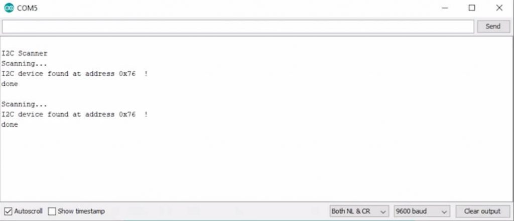
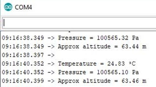
To check the default I2C address of your BMP280 sensor with NodeMCU. Simply upload the I2C Address Scanner code provided below. Now, open the serial monitor to check your BMP280 default I2C address. This code will also help you to check your sensor working or not.
// I2C address Scanner code
 #include <Wire.h>
 void setup()
 {
   Wire.begin();
 Serial.begin(9600);
   while (!Serial);             // Leonardo: wait for serial monitor
   Serial.println("I2C Scanner");
 }
 void loop()
 {
   byte error, address;
   int nDevices;
 Serial.println("Scanning…");
 nDevices = 0;
   for (address = 1; address < 127; address++ )
   {
     // The i2c_scanner uses the return value of
     // the Write.endTransmisstion to see if
     // a device did acknowledge to the address.
     Wire.beginTransmission(address);
     error = Wire.endTransmission();
 if (error == 0) {   Serial.print("I2C device found at address 0x");   if (address < 16)     Serial.print("0");   Serial.print(address, HEX);   Serial.println("  !");   nDevices++; } else if (error == 4) {   Serial.print("Unknown error at address 0x");   if (address < 16)     Serial.print("0");   Serial.println(address, HEX); }
 }
   if (nDevices == 0)
     Serial.println("No I2C devices found");
   else
     Serial.println("done");
 delay(5000);           // wait 5 seconds for next scan
 }
Final Program Code For BMP280 based IoT Weather Station
I have provided the complete code for the BMP280 Based IoT Weather Station using NodeMCU and OLED Display project below. You can simply copy the code to your Arduino IDE and upload it to your NodeMCU ESP8266 development board.
 #include <Wire.h>
 #include <SPI.h>
 #include <Adafruit_Sensor.h>
 #include <Adafruit_BMP280.h>
 #include <Adafruit_GFX.h>
 #include <Adafruit_SSD1306.h>
 #include <Blynk.h>
 #include <ESP8266WiFi.h>
 #include <BlynkSimpleEsp8266.h>
 char auth[] = "xxxxxx-yyyy-zzzzzz";       // You should get Auth Token in the Blynk App.
 char ssid[] = "The IoT Projects";                       // Your WiFi credentials.
 char pass[] = "";
 define SCREEN_WIDTH 128  // OLED display width, in pixels
 define SCREEN_HEIGHT 64  // OLED display height, in pixels
 define OLED_RESET    -1  // Reset pin # (or -1 if sharing reset pin)
 // initialize Adafruit display library
 Adafruit_SSD1306 display(SCREEN_WIDTH, SCREEN_HEIGHT, &Wire, OLED_RESET);
 define SEALEVELPRESSURE_HPA (1013.25)
 Adafruit_BMP280 bmp; // For I2C interface
 //Adafruit_BMP280 bmp(BMP_CS); // hardware SPI
 //Adafruit_BMP280 bmp(BMP_CS, BMP_MOSI, BMP_MISO,  BMP_SCK);
 void setup()
 {
   Serial.begin(9600);
   Blynk.begin(auth, ssid, pass);
   delay(1000);  // wait a second
 // set I2C pins [SDA = GPIO4 (D2), SCL = GPIO5 (D1)], default clock is 100kHz
   //Wire.begin(4, 5);
   Wire.begin();
 // initialize the SSD1306 OLED display with I2C address = 0x3D
   display.begin(SSD1306_SWITCHCAPVCC, 0x3C);
 // clear the display buffer.
   display.clearDisplay();
 display.setTextSize(1);   // text size = 1
   display.setTextColor(WHITE, BLACK);  // set text color to white and black background
 display.setTextWrap(false);           // disable text wrap
   display.setCursor(0, 4);              // move cursor to position (0, 4) pixel
   display.print("WnEnAnTnHnEnR");
   display.setCursor(123, 4);            // move cursor to position (123, 4) pixel
   display.println("S");  display.setCursor(123, display.getCursorY());
   display.println("T");  display.setCursor(123, display.getCursorY());
   display.println("A");  display.setCursor(123, display.getCursorY());
   display.println("T");  display.setCursor(123, display.getCursorY());
   display.println("I");  display.setCursor(123, display.getCursorY());
   display.println("O");  display.setCursor(123, display.getCursorY());
   display.println("N");
   display.display();        // update the display
   // initialize the BME280 sensor
   Serial.println(F("BMP280 test"));
 if (!bmp.begin()) {
     // connection error or device address wrong!
     Serial.println(F("Could not find a valid BMP280 sensor, check wiring!"));
     display.setCursor(34, 23);
     display.print("Connection");
     display.setCursor(49, 33);
     display.print("Error");
     display.display();        // update the display
     while (1) // stay here
       delay(1000);
   }
   display.setCursor(29, 0);
   display.print("TEMPERATURE:");
   display.setCursor(36, 23);
   display.print("Pressure:");
   display.setCursor(38, 46);
   display.print("Altitude:");
   display.display();        // update the display
 }
 void loop()
 {
   Blynk.run(); // Initiates Blynk
 // read temperature, humidity and pressure from the BME280 sensor
   float temp = bmp.readTemperature();    // get temperature in degree Celsius
   float pres = bmp.readPressure()/100;       // get pressure in Pa
   float alti = bmp.readAltitude(SEALEVELPRESSURE_HPA);       // get altitude in meter

   delay(1000);  // wait a second
 // print data on the LCD
   // print temperature
   Serial.print("Temperature = ");
   Serial.print(temp);
   Serial.println("*C");
   display.setCursor(37, 10);
   if (temp < 0)
     display.printf("-%02u.%02u C", (int)abs(temp) % 100, (int)(abs(temp) * 100) % 100 );
   else
     display.printf(" %02u.%02u C", (int)temp % 100, (int)(temp * 100) % 100 );
 // print degree symbols ( ° )
   display.drawRect(75, 10, 3, 3, WHITE);
 //print pressure
   Serial.print("Pressure = ");
   Serial.print(pres);
   Serial.println("hPa");
   display.setCursor(38, 33);
   display.printf("%02u hPa", (int)(pres));
   //print Altitude
   Serial.print("Approx. Altitude = ");
   Serial.print(alti);
   Serial.println("m");
   display.setCursor(38, 56);
   display.printf("%02u meter", (int)(alti));
 // update the display
   display.display();
 delay(1000);  // wait a second
 Serial.println();
   Blynk.virtualWrite(V1, temp); // For Temperature
   Blynk.virtualWrite(V2, pres); // For Pressure
   Blynk.virtualWrite(V3, alti); //For Approx. Altitude
   delay(1000);
 }
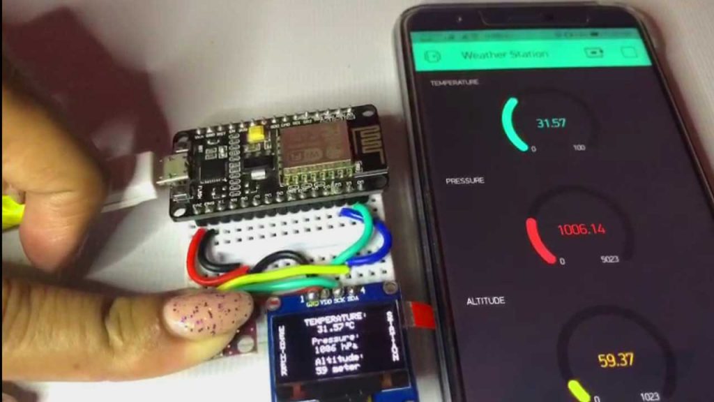
When the code is uploaded, ESP8266 will connect to the Blynk server. It initializes the sensor and prints parameters in OLED Display. Now you can check the Blynk app on your mobile phone. The mobile phone receives BMP280 weather station data.
Demonstration: BMP280 based IoT Weather Station
Now, if you have followed all the mentioned steps and connected everything accordingly, then you should see the weather station data on your OLED display and Blynk application with no errors.
We have embedded the video tutorial on BMP280 Based IoT Weather Station using NodeMCU ESP8266 and OLED Display below:
Conclusion
So, this is another BMP280 Based IoT Weather Station using NodeMCU ESP8266 and OLED Display, which will monitor the temperature, atmospheric pressure, and altitude data on Blynk IoT Application. I hope you love this project. If you did, please share it with others.

Hola quisiera preguntar que cuando hago la recopilación me sale un error en la linea 18 define SEALEVELPRESSURE, el error me dice ‘define’ does not name a type, seria tan amable de indicarme que debo hacer para solucionar este problema. Muchas gracias
Add # before define.
your website is very good and well assembled
Good day.
I don’t know where I made the error but Connection Error lights up on the display