Home Automation with Arduino IoT Cloud using ESP8266
Control your Home Appliances with ESP8266 & Arduino IoT Cloud
Overview: Home Automation with Arduino IoT Cloud & ESP8266
In this project, we are going to make Home Automation with Arduino IoT Cloud using ESP8266. Recently the Arduino Community launched an IoT platform called Arduino IoT Cloud. Using this IoT Platform you can interface multiple devices to each other and permit them to exchange real-time data. Besides this, you will be able to monitor and control the data from anywhere using a simple interface.
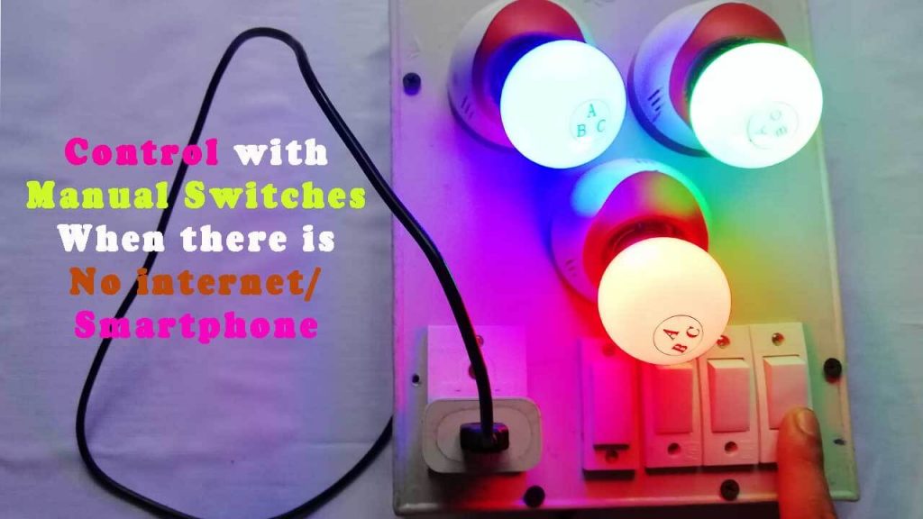
The best part of this project is you can control the relays from anywhere in the world. Not only that, you can control your appliances through the manual switches if no internet is available. To find out more about the Arduino IoT Cloud, you can undergo this documentation.
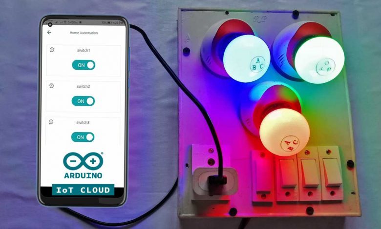
In this project, you will be able to control multiple home appliances from the Arduino IoT Cloud Dashboard. We are going to interface 4 channel relay module with the ESP8266 NodeMCU Development board & send the ON/OFF commands either from the smartphone dashboard or from Computer Dashboard to Control Relay, Light, or anything else. So, let’s see how can deploy this complete system.
But before that, you can check some of our previous Home Automation Projects made using ESP8266:
- Temperature Controlled Home Automation using Arduino
- Home Automation with ESP8266 Web Server
- IoT Based Voice Controlled Home Automation Using NodeMCU
- Light Control using Google Firebase & ESP8266
- Battery Status Monitoring System using ESP8266 & Arduino IoT Cloud
Components Required
For this project, we will need an ESP8266 NodeMCU Board, 4 channel relay, a few jumper wires, and a breadboard. For this demo, I am controlling 3 light bulbs and 1 fan. But you can control any other electrical appliances.
We can easily purchase all the components from the Amazon links below:
| S.N | Components Name | Quantity | |
|---|---|---|---|
| 1 | NodeMCU ESP8266 12-E Development Board | 1 | https://amzn.to/3kiLhQ3 |
| 2 | 4 channel Relay Module | 1 | https://amzn.to/2Z69lid |
| 3 | Light Bulb holder | 4 | https://amzn.to/3nCehoZ |
| 4 | 5V Micro USB Charger | 1 | https://amzn.to/3CefHdu |
| 5 | 4 Switch Board | 1 | https://amzn.to/3hCP6iq |
| 6 | Few jumpers wires | 20 | https://amzn.to/3klh0A4 |
| 7 | 12-volt adaptor | 1 | https://amzn.to/3zr4ky1 |
| 8 | 7805 Voltage Regulator | 1 | https://amzn.to/3tJ0yxL |
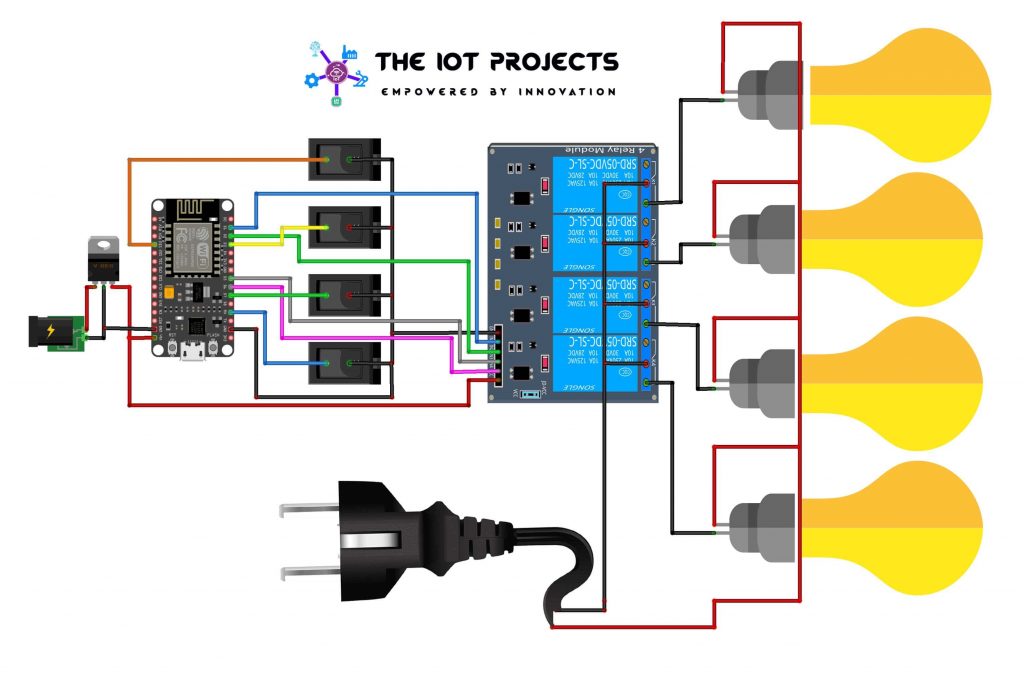
Circuit Diagram & Hardware
The circuit for Home Automation using Arduino IoT Cloud & ESP8266 is very simple. I used Fritzing software to draw this schematic. The below diagram is simply for the breadboard Assembly.
| NodeMCU ESP8266 | 4-Channel Relay |
| D1 | IN1 |
| D2 | IN2 |
| D5 | IN3 |
| D6 | IN4 |
| Vin | 5V |
| GND | GND |
| NodeMCU ESP8266 | Switches |
| SD3 | Switch 1 |
| D3 | Switch 2 |
| D7 | Switch 3 |
| RX | Switch 4 |
| GND | To all second terminal of Switch |
| Relay | Light Bulb |
| Common | The -ve terminal of AC |
| NO | GND |
| The +Ve terminal of AC | The +Ve terminal of Bulb |
The ESP8266 board has a few GPIOs Pins. In this project, we will use D1, D2, D5 & D6 GPIO pins for controlling the 4-channel relay. Similarly, GPIO SD3, D3, D7 & RX connected with the Manual Switches to control the relay manually. Across the output of the relay, I am using 3 bulbs and 1 fan for demonstration.
I have also connected a 5 pin socket to the board, which is directly connected to the main power supply to power the NodeMCU ESP8266 using an old mobile phone charger. But, you can also use a 12V DC Adapter to power the circuit as the output of the 7805 Voltage Regulator IC provides 5V, which can be an interface with the Vin pin of ESP8266.
Project PCB Gerber File & PCB Ordering Online
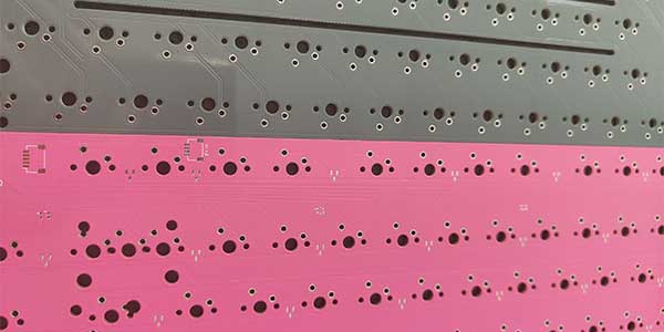
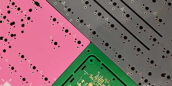
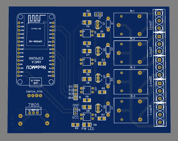
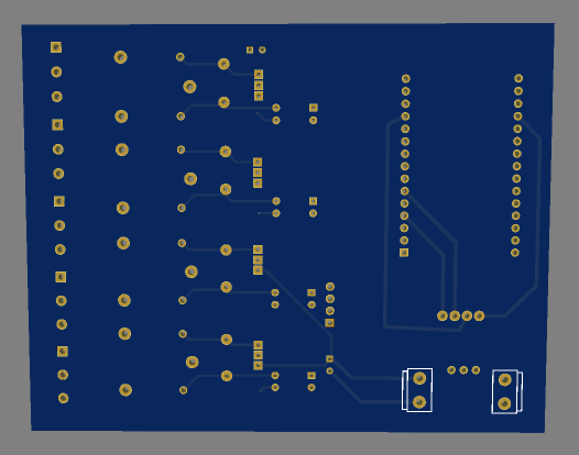
If you don’t want to assemble the circuit on a breadboard, and you want PCB for this project, then here is the PCB for you. The PCB Board for Home Automation using ESP8266 looks something like below.
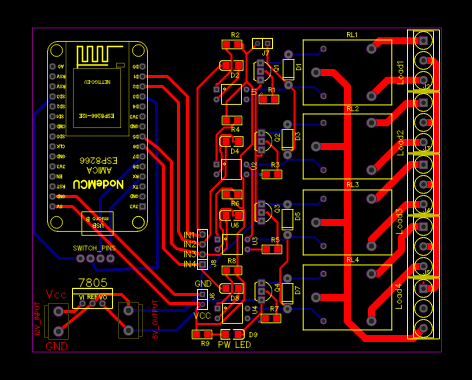
The Gerber File for the PCB is given below. You can simply download the Gerber File and order the PCB from https://www.PCBWay.com/
Steps to order PCB from PCBWay
To order the PCB first visit PCBWay.com.
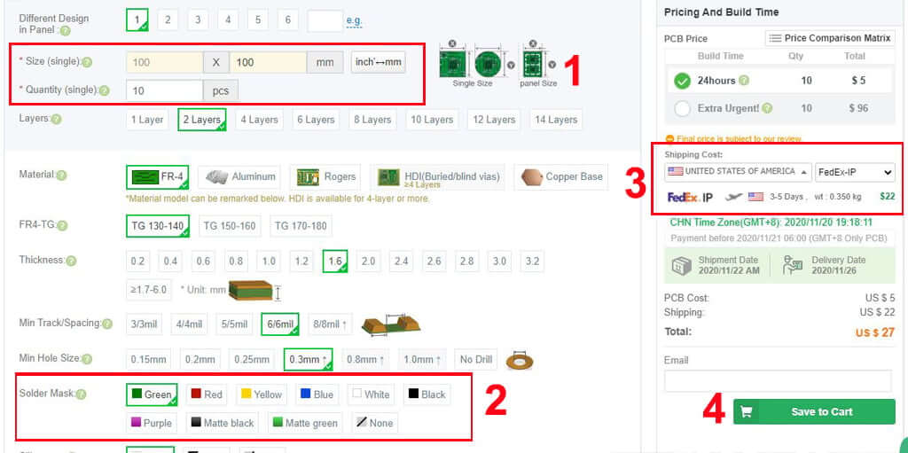
Now enter the following details:
- PCB Size (Length & Width) in mm & PCB quantity
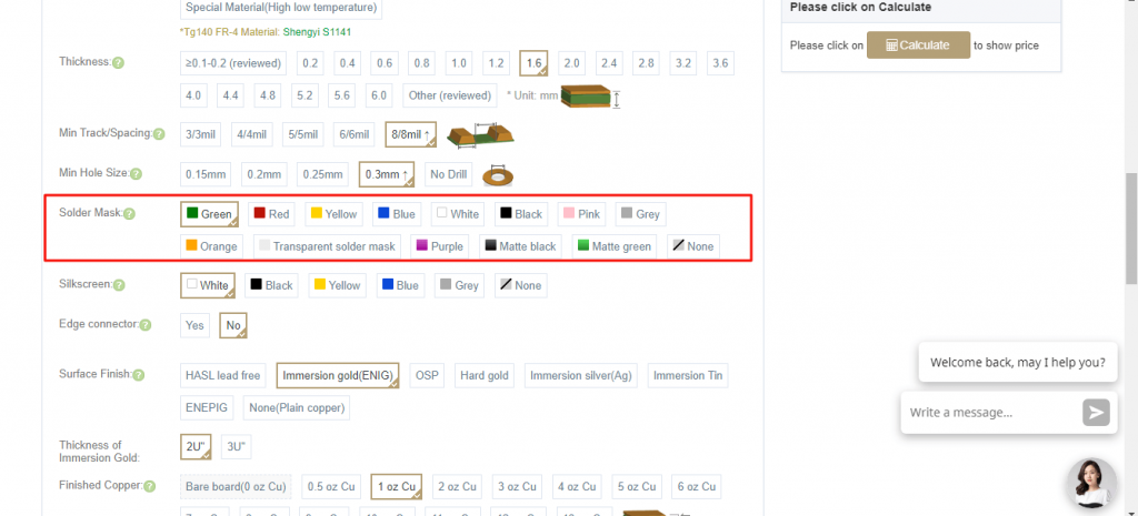
- Select masking color for the PCB
- Select country and shipping method
- Click on the “Save to Cart” button
If you need some advanced features in your PCB to produce Pink, Orange, Grey, or even a Transparent Solder Mask you can get it here: High-Quality Advanced PCB. You can also get a full Black Core PCB from PCBWay.
Now click on the “Add Gerber Files” to upload the PCB Gerber file.
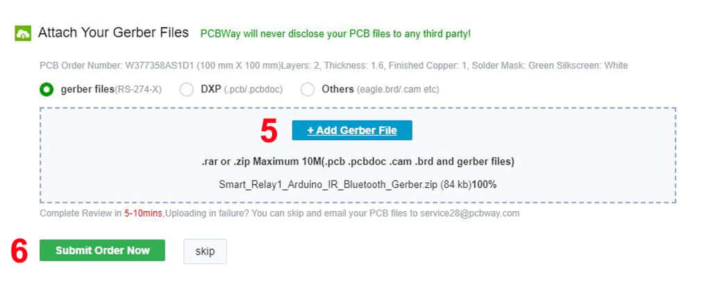
Then click on the “Submit Order Now” to place the order.
After that, they will review the Gerber file and accordingly confirm the order. Generally, you will receive the PCB within a week. But, It also depends upon the shipping method that you have chosen.
Setting Up Arduino IoT Cloud Dashboard
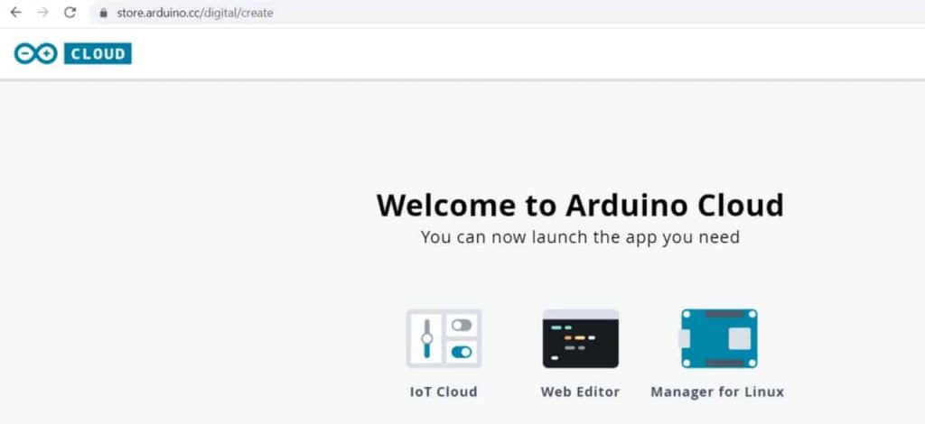
Now it’s time to set up the Arduino IoT Cloud Dashboard. So, go to the Arduino Store. Click on IoT Cloud.
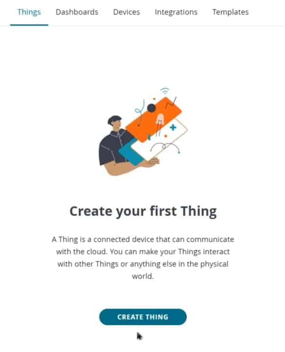
Then you need to create a Thing first. For that, click on add variable.
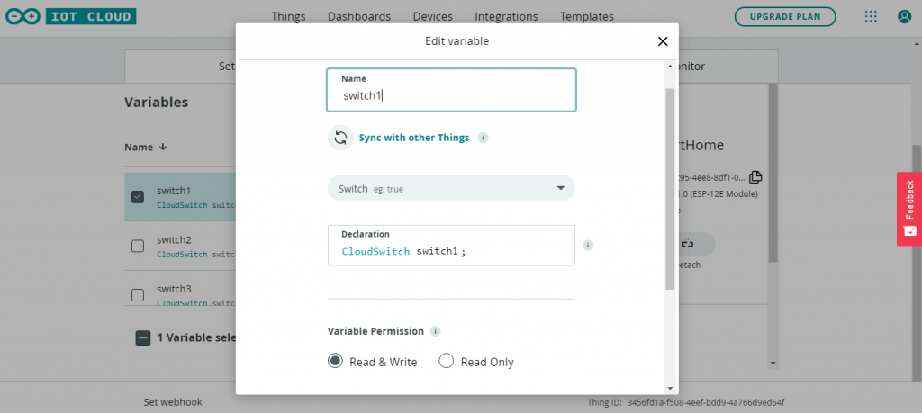
Name the variable anything like Switch1. In the variable type, select cloud switch. So an automatic declaration of variables will be done. Then click on Add variable button to create the first variable.
Similarly, create other three variables with names Switch2, Switch3, and Switch4.
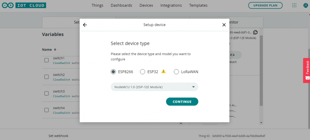
Now, we need to configure a device as well. For that, select the device option. From the list, select a 3rd party device. Then select ESP8266. From this list, select NodeMCU1.0 ESP-12E Module.
Click to continue and give any name to the device. Then click next. For this tutorial, I am providing “SmartHome“
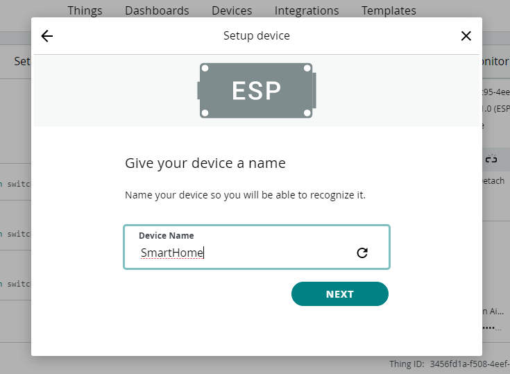
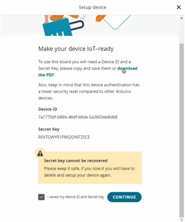
So device ID & Secret Key is created here. Save this device ID for the coding part. Or simply download this PDF File which has the information of Secret Key. Then click on continue.
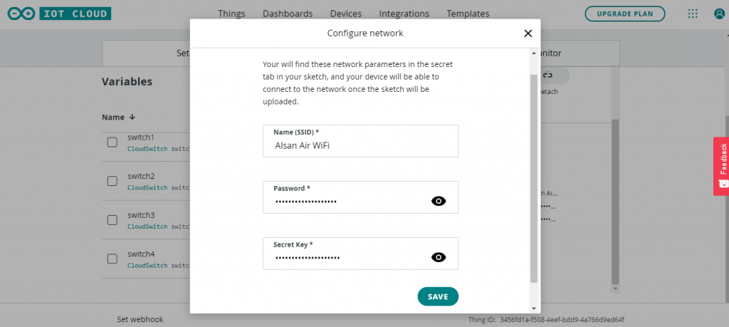
Now again, you need to set up the Network Credentials. So input your SSID, Password, and Secret Key that you created earlier. Finally, everything is set now.
Go to the dashboard. Here we need to build a dashboard.
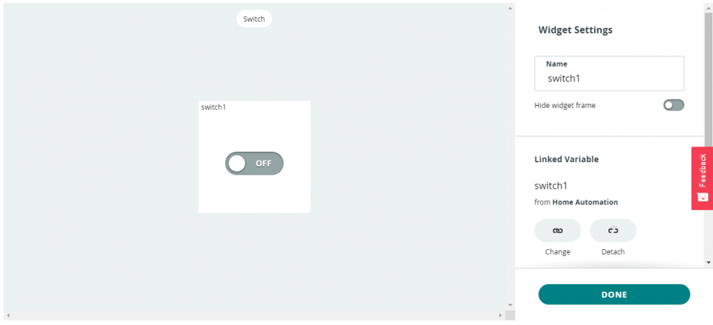
From the edit option, add a variable. So select switch. Give it a name switch1. Then link a variable. Click on Done. Similarly, add 3 more variables for 3 different switches and link the variable to them. You can arrange and resize the widget as your wish.
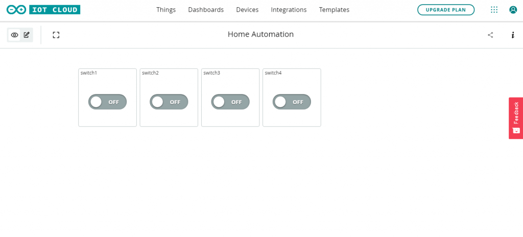
So finally, we are done with the IoT dashboard setup.
Source Code/Program
Let’s go to the sketch for Home Automation with Arduino IoT Cloud & ESP8266.
There are 4 variables with CloudSwitch automatically declared.
CloudSwitch switch1;
CloudSwitch switch2;
CloudSwitch switch3;
CloudSwitch switch4;
In the setup part, we have defined 4 pins of ESP8266 as output. Those 4 pins are pins D1, D2, D5, and D6. We have used the INPUT_PULLUP function in code instead of using the pull-up resistors with each switch connected to GPIO SD3, D3, D7 & RX.
// For Relays
  pinMode(RelayPin1, OUTPUT);
  pinMode(RelayPin2, OUTPUT);
  pinMode(RelayPin3, OUTPUT);
  pinMode(RelayPin4, OUTPUT);

// For Switches
  pinMode(SwitchPin1, INPUT_PULLUP);
  pinMode(SwitchPin2, INPUT_PULLUP);
  pinMode(SwitchPin3, INPUT_PULLUP);
  pinMode(SwitchPin4, INPUT_PULLUP);
Initialize relays with high logic, so that all appliances are turned off initially.
  //During Starting all Relays should TURN OFF
  digitalWrite(RelayPin1, HIGH);
  digitalWrite(RelayPin2, HIGH);
  digitalWrite(RelayPin3, HIGH);
  digitalWrite(RelayPin4, HIGH);
ButtonConfig is used to control the appliances manually using switches. It is useful when there is no internet or smartphone to control this system. This means Manual switches work as usual for controlling appliances.
ButtonConfig config1;
AceButton button1(&config1);
ButtonConfig config2;
AceButton button2(&config2);
ButtonConfig config3;
AceButton button3(&config3);
ButtonConfig config4;
AceButton button4(&config4);
   //Manual Switch Control check in loop
    button1.check();
    button2.check();
    button3.check();
    button4.check();
As per the source code, when the control pins of the relay module receive the LOW signal the respective relay will turn on and the relay will turn off for the HIGH signal in the control pin.
if (switch1 == 1)
  {
    digitalWrite(RelayPin1, LOW);
    Serial.println("Device1 ON");
    toggleState_1 = 1;
  }
  else
  {
    digitalWrite(RelayPin1, HIGH);
    Serial.println("Device1 OFF");
    toggleState_1 = 0;
  }
}
Here is the complete code that you can use for this project.
ESP8266_Home_Automation_with_Arduino_IoT.ino
/*
Sketch generated by the Arduino IoT Cloud Thing "Home Automation"
https://create.arduino.cc/cloud/things/3456fd1a-f508-4eef-bdd9-4a766d9ed64f
Arduino IoT Cloud Variables description
The following variables are automatically generated and updated when changes are made to the Thing
CloudSwitch switch4;
CloudSwitch switch2;
CloudSwitch switch1;
CloudSwitch switch3;
Variables which are marked as READ/WRITE in the Cloud Thing will also have functions
which are called when their values are changed from the Dashboard.
These functions are generated with the Thing and added at the end of this sketch.
*/
#include "thingProperties.h"
#include <AceButton.h>
using namespace ace_button;
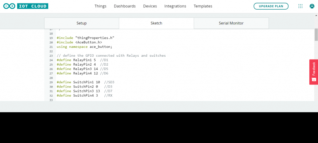
// define the GPIO connected with Relays and switches
#define RelayPin1 5 //D1
#define RelayPin2 4 //D2
#define RelayPin3 14 //D5
#define RelayPin4 12 //D6
#define SwitchPin1 10 //SD3
#define SwitchPin2 0 //D3
#define SwitchPin3 13 //D7
#define SwitchPin4 3 //RX
#define wifiLed 16 //D0
int toggleState_1 = 0; //Define integer to remember the toggle state for relay 1
int toggleState_2 = 0; //Define integer to remember the toggle state for relay 2
int toggleState_3 = 0; //Define integer to remember the toggle state for relay 3
int toggleState_4 = 0; //Define integer to remember the toggle state for relay 4
ButtonConfig config1;
AceButton button1(&config1);
ButtonConfig config2;
AceButton button2(&config2);
ButtonConfig config3;
AceButton button3(&config3);
ButtonConfig config4;
AceButton button4(&config4);
void handleEvent1(AceButton*, uint8_t, uint8_t);
void handleEvent2(AceButton*, uint8_t, uint8_t);
void handleEvent3(AceButton*, uint8_t, uint8_t);
void handleEvent4(AceButton*, uint8_t, uint8_t);
void relayOnOff(int relay) {
switch (relay) {
case 1:
if (toggleState_1 == 0) {
digitalWrite(RelayPin1, LOW); // turn on relay 1
toggleState_1 = 1;
Serial.println("Device1 ON");
}
else {
digitalWrite(RelayPin1, HIGH); // turn off relay 1
toggleState_1 = 0;
Serial.println("Device1 OFF");
}
delay(100);
break;
case 2:
if (toggleState_2 == 0) {
digitalWrite(RelayPin2, LOW); // turn on relay 2
toggleState_2 = 1;
Serial.println("Device2 ON");
}
else {
digitalWrite(RelayPin2, HIGH); // turn off relay 2
toggleState_2 = 0;
Serial.println("Device2 OFF");
}
delay(100);
break;
case 3:
if (toggleState_3 == 0) {
digitalWrite(RelayPin3, LOW); // turn on relay 3
toggleState_3 = 1;
Serial.println("Device3 ON");
} else {
digitalWrite(RelayPin3, HIGH); // turn off relay 3
toggleState_3 = 0;
Serial.println("Device3 OFF");
}
delay(100);
break;
case 4:
if (toggleState_4 == 0) {
digitalWrite(RelayPin4, LOW); // turn on relay 4
toggleState_4 = 1;
Serial.println("Device4 ON");
}
else {
digitalWrite(RelayPin4, HIGH); // turn off relay 4
toggleState_4 = 0;
Serial.println("Device4 OFF");
}
delay(100);
break;
default : break;
}
}
void setup() {
// Initialize serial and wait for port to open:
Serial.begin(9600);
// This delay gives the chance to wait for a Serial Monitor without blocking if none is found
delay(1500);
// Defined in thingProperties.h
initProperties();
// Connect to Arduino IoT Cloud
ArduinoCloud.begin(ArduinoIoTPreferredConnection);
setDebugMessageLevel(2);
ArduinoCloud.printDebugInfo();
pinMode(RelayPin1, OUTPUT);
pinMode(RelayPin2, OUTPUT);
pinMode(RelayPin3, OUTPUT);
pinMode(RelayPin4, OUTPUT);
pinMode(wifiLed, OUTPUT);
pinMode(SwitchPin1, INPUT_PULLUP);
pinMode(SwitchPin2, INPUT_PULLUP);
pinMode(SwitchPin3, INPUT_PULLUP);
pinMode(SwitchPin4, INPUT_PULLUP);
//During Starting all Relays should TURN OFF
digitalWrite(RelayPin1, HIGH);
digitalWrite(RelayPin2, HIGH);
digitalWrite(RelayPin3, HIGH);
digitalWrite(RelayPin4, HIGH);
digitalWrite(wifiLed, HIGH); //Turn OFF WiFi LED
config1.setEventHandler(button1Handler);
config2.setEventHandler(button2Handler);
config3.setEventHandler(button3Handler);
config4.setEventHandler(button4Handler);
}
void loop() {
ArduinoCloud.update();
//Manual Switch Control
button1.check();
button2.check();
button3.check();
button4.check();
if (WiFi.status() != WL_CONNECTED)
{
digitalWrite(wifiLed, HIGH); //Turn OFF WiFi LED
}
else{
digitalWrite(wifiLed, LOW); //Turn ON WiFi LED
}
}
void onSwitch1Change() {
if (switch1 == 1)
{
digitalWrite(RelayPin1, LOW);
Serial.println("Device1 ON");
toggleState_1 = 1;
}
else
{
digitalWrite(RelayPin1, HIGH);
Serial.println("Device1 OFF");
toggleState_1 = 0;
}
}
void onSwitch2Change() {
if (switch2 == 1)
{
digitalWrite(RelayPin2, LOW);
Serial.println("Device2 ON");
toggleState_2 = 1;
}
else
{
digitalWrite(RelayPin2, HIGH);
Serial.println("Device2 OFF");
toggleState_2 = 0;
}
}
void onSwitch3Change() {
if (switch3 == 1)
{
digitalWrite(RelayPin3, LOW);
Serial.println("Device2 ON");
toggleState_3 = 1;
}
else
{
digitalWrite(RelayPin3, HIGH);
Serial.println("Device3 OFF");
toggleState_3 = 0;
}
}
void onSwitch4Change() {
if (switch4 == 1)
{
digitalWrite(RelayPin4, LOW);
Serial.println("Device4 ON");
toggleState_4 = 1;
}
else
{
digitalWrite(RelayPin4, HIGH);
Serial.println("Device4 OFF");
toggleState_4 = 0;
}
}
void button1Handler(AceButton* button, uint8_t eventType, uint8_t buttonState) {
Serial.println("EVENT1");
relayOnOff(1);
}
void button2Handler(AceButton* button, uint8_t eventType, uint8_t buttonState) {
Serial.println("EVENT2");
relayOnOff(2);
}
void button3Handler(AceButton* button, uint8_t eventType, uint8_t buttonState) {
Serial.println("EVENT3");
relayOnOff(3);
}
void button4Handler(AceButton* button, uint8_t eventType, uint8_t buttonState) {
Serial.println("EVENT4");
relayOnOff(4);
}
thingproperties.h
// Code generated by Arduino IoT Cloud, DO NOT EDIT.

#include <ArduinoIoTCloud.h>
#include <Arduino_ConnectionHandler.h>


const char THING_ID[]           = "xxxxxx-xxxxx";
const char DEVICE_LOGIN_NAME[]  = "xxx-xxxx-xxx-xxx";

const char SSID[]               = SECRET_SSID;    // Network SSID (name)
const char PASS[]               = SECRET_PASS;    // Network password (use for WPA, or use as key for WEP)
const char DEVICE_KEY[]  = SECRET_DEVICE_KEY;    // Secret device password

void onSwitch4Change();
void onSwitch2Change();
void onSwitch1Change();
void onSwitch3Change();

CloudSwitch switch4;
CloudSwitch switch2;
CloudSwitch switch1;
CloudSwitch switch3;

void initProperties(){

  ArduinoCloud.setBoardId(DEVICE_LOGIN_NAME);
  ArduinoCloud.setSecretDeviceKey(DEVICE_KEY);
  ArduinoCloud.setThingId(THING_ID);
  ArduinoCloud.addProperty(switch4, READWRITE, ON_CHANGE, onSwitch4Change);
  ArduinoCloud.addProperty(switch2, READWRITE, ON_CHANGE, onSwitch2Change);
  ArduinoCloud.addProperty(switch1, READWRITE, ON_CHANGE, onSwitch1Change);
  ArduinoCloud.addProperty(switch3, READWRITE, ON_CHANGE, onSwitch3Change);

}

WiFiConnectionHandler ArduinoIoTPreferredConnection(SSID, PASS);
arduino_secrets.h
#define SECRET_SSID "xxx-xxx"
#define SECRET_PASS "xx-xx-xx"
#define SECRET_DEVICE_KEY "xxxx-xxxxx-xxxx"
Apart from the code part, we need to upload the code. But before that, we need to install an Agent to flash the code directly from the browser. Follow the instruction on your screen to install the agent.
Once the driver is installed, the COM port will appear. Then select the ESP8266 NodeMCU Board from the list and the COM port as well. Then, upload the code. It will take some time to upload the code and when it’s done, some upload success message will appear.
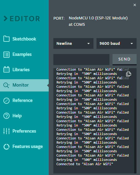
Testing: Home Automation with Arduino IoT Cloud & ESP8266
After uploading the code, open the Serial Monitor. It will show WiFi connection is established and then the device is connected to Arduino IoT Cloud Dashboard.
Open the dashboard now, so you can see the switch can be turned ON and OFF. You can do the initial testing. Here we can send the command to see whether the on-board LED from the Relay will turn ON or not.
You can control the light bulb from Mobile Dashboard. For that install Arduino IoT Remote from Playstore. Sign in using the same ID and password. Open the dashboard to control the appliances easily.
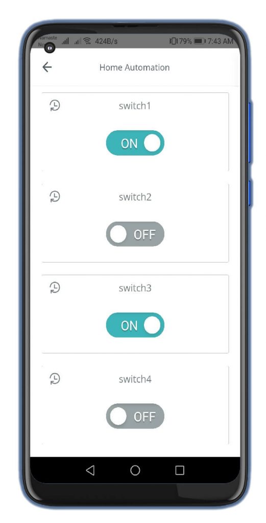
Besides this, you can also manually control the appliances using switches.
Video Tutorial & Guide
Conclusion
So, that’s all about Home Automation with Arduino IoT Cloud using ESP8266. I hope you love this two-way home automation project. You can make this project easily at your home and show it to your family members.


