Smart Notice Board with ESP8266 & Dot Matrix LED Display
Dot Matrix LED Display Controller with Web Dashboard using ESP8266
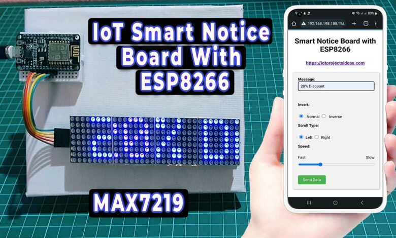
Overview: Smart Notice Board with ESP8266
In this project, we are going to learn how to make a Smart Notice Board using an ESP8266 microcontroller and a Dot Matrix LED Display. We’ll use the ESP8266 WiFi module to connect to the internet and the Dot Matrix LED display to display our messages. This project is beginner-friendly and can be done by anyone who has a basic understanding of electronics and programming.
In our project, the ESP8266 WiFi module is interfaced with a 4-in-1 MAX7219 Dot Matrix LED Display that shows messages. WiFiManager library is used to set up and configure the WiFi network. It allows you to connect your ESP8266 to different wifi Access Points without having to hard-code and upload new code to your board. After a successful WiFi setup, the local IP address of NodeMCU is displayed on a Dot Matrix LED Display. You can access the web page using the same IP address. Users can enter messages and choose different effects, such as scrolling left or scrolling right, scroll speed, and inversion of the display from a web interface.
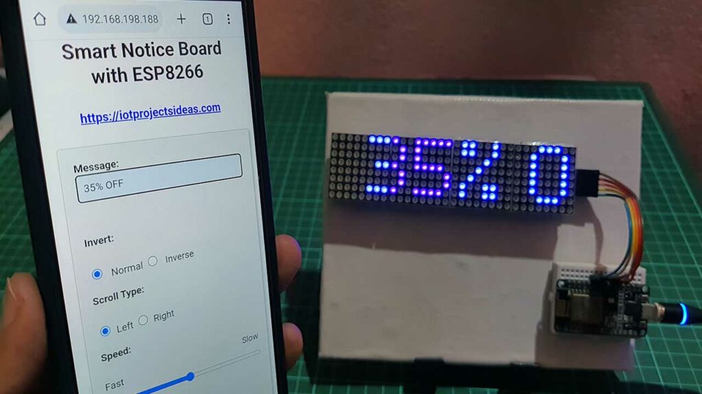
By using this DIY project, which is a digital display system. Institutions can eliminate the need for paper as all the information can be displayed on the Dot Matrix LED displays. This can reduce paper waste and save resources. Additionally, the risk of errors can be minimized as the information can be easily updated and corrected electronically, instead of having to manually change paper-based displays. Overall, this project can help to make information management more efficient, environmentally friendly, and accurate.
Components Required
Here’s what we’ll need for making this web-controlled smart notice board. You can easily purchase them from the links provided below.
| S.N | COMPONENTS NAME | QUANTITY | PURCHASE LINKS |
|---|---|---|---|
| 1 | NodeMCU ESP8266 Board | 1 | Amazon | AliExpress |
| 2 | MAX7219 Dot Matrix LED Display | 1 | Amazon | AliExpress |
| 3 | Breadboard | 1 | Amazon | AliExpress |
| 4 | 5V 2A Power Supply | 1 | Amazon | AliExpress |
| 5 | Jumper Cables | 5 | Amazon | AliExpress |
Dot Matrix LED Display
LED matrices come in various styles such as single color, dual color, multi-color, or RGB LED matrix, and dimensions include 5×7, 8×8, 16×16, 8×32, 32×32, etc.
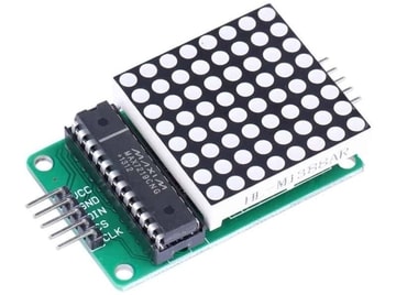
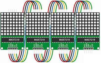
This 8×32 LED matrix Display is composed of 4 single modules connected internally. Each module contains the same Maxim MAX7219 chip and has the same power and data connections, making the modules separable.
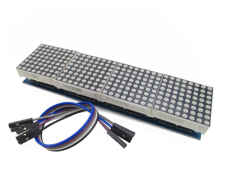
Pin Configuration
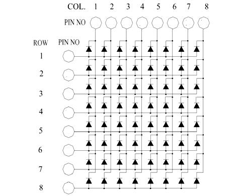
The 8×8 LED matrix has 8 positive and 8 negative terminals, with 8 negative terminals representing the columns and 8 positive terminals the rows.
The 4-in-1 8×8 LED matrices are connected via MAX7219 pins.
MAX7219 LED Driver IC
LED matrices can be driven either parallel (with parallel data sent for each row or column) or serial (with data sent serially and an IC converting it to parallel data).
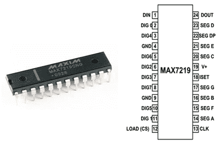
The MAX7219 is a common cathode display driver with serial input and parallel output, used to interface 64 individual LEDs with microprocessors or microcontrollers. The 8×8 LED matrix is connected to the MAX7219, receiving data input from the Arduino board.
Smart Notice Board with ESP8266 & Dot Matrix LED Display
The hardware of the Smart Notice Board project consists of a 4-in-1 Dot Matrix LED Display and an ESP8266 WiFi Module. The input port is on the left side of the display and is connected to a Microcontroller’s GPIO pins. The output port, on the right side, allows for expanding or adding additional LED Displays.
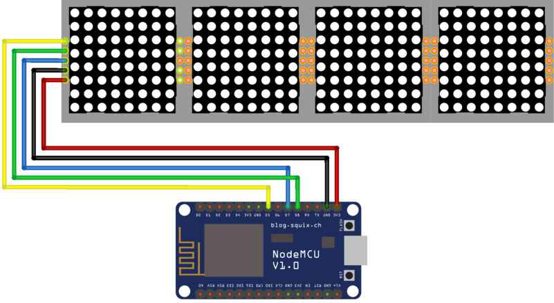
Here’s the circuit diagram for this project. It’s very straightforward. Connect the data pin of the LED display to the D7 pin of the ESP8266. The clock pin to the D5 pin, and the load pin to the D6 pin. Connect the VCC and GND pins of the LED display to the 3.3V and GND pins of the ESP8266 respectively.
I recommend using a 5V 2A DC power supply. As current consumption is higher and ESP8266 is not capable of supplying current if LED is used at full brightness.
Project PCB Gerber File & PCB Ordering Online
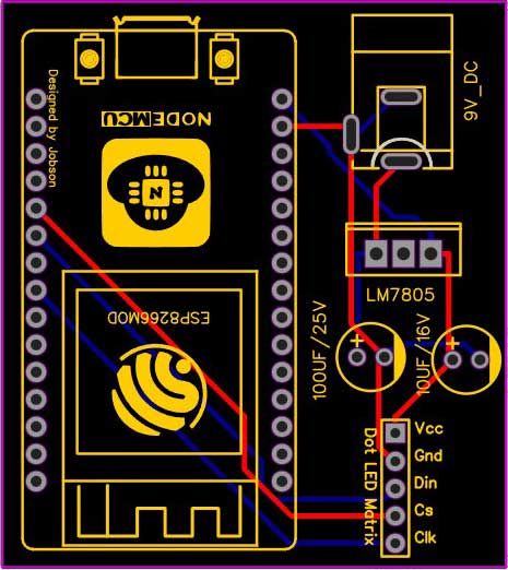
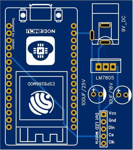
If you don’t want to assemble the circuit on a zero PCB and you want PCB for the project, then here is the PCB for you. The PCB Board for this project looks something like below.
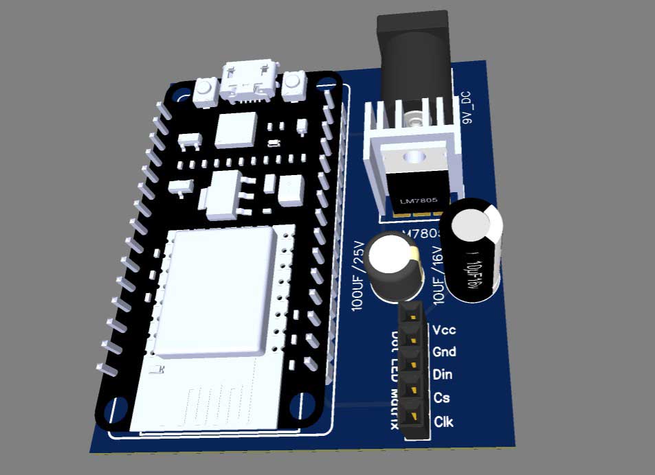
The Gerber File for the PCB is given below. You can simply download the Gerber File and order the PCB from PCBWay.com.
PCBWay Christmas Big Sales is going on, please visit the link provided to get extra discounts and offers.
https://www.pcbway.com/activity/christmas2023.html
Now you can visit the PCBWay official website by clicking here: PCBWay.com. So you will be directed to the PCBWay website.

You can now upload the Gerber File to the Website and place an order. The PCB quality is superb & high standard. That is why most people trust PCBWay for PCB & PCBA Services. PCBWay is a leading manufacturer of high-quality PCBs and offers a wide range of services, including PCB fabrication, assembly, and components sourcing.
Source Code/program
Now let’s move on to the programming part. We’ll be using the Arduino IDE to program the ESP8266. We need to install the following libraries:
You can install these libraries from the library manager in the Arduino IDE.
Now connect the micro USB cable to the NodeMCU ESP8266 board. Choose the correct Board and COM Port from the tools menu. Then upload the following code to it.
// Smart Notice Board with ESP8266 & Dot Matrix LED Display
#include <ESP8266WiFi.h>
#include <WiFiManager.h>
#include <MD_Parola.h>
#include <MD_MAX72xx.h>
#include <SPI.h>
// Turn on debug statements to the serial output
#define  DEBUG  0

#if  DEBUG
#define PRINT(s, x) { Serial.print(F(s)); Serial.print(x); }
#define PRINTS(x) Serial.print(F(x))
#define PRINTX(x) Serial.println(x, HEX)
#else
#define PRINT(s, x)
#define PRINTS(x)
#define PRINTX(x)
#endif
#define HARDWARE_TYPE MD_MAX72XX::FC16_HW
#define MAX_DEVICES 4
#define CS_PIN    15 // or SS

// HARDWARE SPI
MD_Parola P = MD_Parola(HARDWARE_TYPE, CS_PIN, MAX_DEVICES);
// WiFi Server object and parameters
WiFiServer server(80);

// Scrolling parameters
uint8_t frameDelay = 25;  // default frame delay value
textEffect_t  scrollEffect = PA_SCROLL_LEFT;

// Global message buffers shared by Wifi and Scrolling functions
#define BUF_SIZE  512
char curMessage[BUF_SIZE];
char newMessage[BUF_SIZE];
bool newMessageAvailable = false;
const char WebResponse[] = "HTTP/1.1 200 OKnContent-Type: text/htmlnn";

const char WebPage[] =
  "<!DOCTYPE html>n"
  "<html>n"
  "<head>n"
  "<meta name='viewport' content='width=device-width, initial-scale=1'>n"
  "<title>Smart Notice Board</title>n"
  "<script>n"
  "strLine = '';n"
  "n"
  "function SendData() {n"
  "  nocache = '/&nocache=' + Math.random() * 1000000;n"
  "  var request = new XMLHttpRequest();n"
  "  strLine = '&MSG=' + document.getElementById('data_form').Message.value;n"
  "  strLine = strLine + '/&SD=' + document.getElementById('data_form').ScrollType.value;n"
  "  strLine = strLine + '/&I=' + document.getElementById('data_form').Invert.value;n"
  "  strLine = strLine + '/&SP=' + document.getElementById('data_form').Speed.value;n"
  "  request.open('GET', strLine + nocache, false);n"
  "  request.send(null);n"
  "}n"
  "</script>n"
  "<style>n"
  "  body {n"
  "    font-family: Arial, sans-serif;n"
  "    margin: 10px;n"
  "    padding: 10px;n"
  "  }n"
  "  n"
  "  .container {n"
  "    max-width: 600px;n"
  "    margin: 0 auto;n"
  "    text-align: center;n"
  "  }n"
  "  n"
  "  p {n"
  "    font-size: 30px;n"
  "    margin-top: 10px;n"
  "  }n"
  "  n"
  "  form {n"
  "    margin-top: 10px;n"
  "    display: inline-block;n"
  "    text-align: left;n"
  "    width: 60%;n"
  "  }n"
  "  n"
  "  input[type='text'] {n"
  "    padding: 10px;n"
  "    font-size: 16px;n"
  "    width: 100%;n"
  "    margin-bottom: 20px;n"
  "    box-sizing: border-box;n"
  " }n"

  "  label {n"
  "    font-size: 16px;n"
  "   margin-bottom: 10px;n"
  "    display: block;n"
  "  }n"

  "  input[type='radio'] {n"
  "    margin-right: 10px;n"
  "  }n"

  "  input[type='submit'] {n"
  "    padding: 10px 20px;n"
  "    font-size: 18px;n"
  "    background-color: #3F51B5;n"
  "    color: #fff;n"
  "    border: 0;n"
  "    margin-top: 5px;n"
  "    cursor: pointer;n"
  "  }n"

  "  @media only screen and (max-width: 600px) {n"
  "    form {n"
  "      width: 100%;n"
  "    }n"
  "  }n"
  "</style>n"
  "</head>n"
  "<body>n"
  "  <div class='container'>n"
  "    <p><b>Smart Notice Board with ESP8266</b></p>n"
  "    <h3><b><a href='https://iotprojectsideas.com'>https://iotprojectsideas.com</a></b></h3>n"
  "  <form id='data_form' name='frmText'>n"
  " <label>Message:<br><input type='text' name='Message' maxlength='255'></label>n"
  "  <br><br>n"
  "  <label>Invert:</label><br>n"
  "  <input type = 'radio' name = 'Invert' value = '0' checked> Normal n"
  "  <input type = 'radio' name = 'Invert' value = '1'> Inverse n"
  "  <br><br>n"
  "  <label>Scroll Type:</label><br>n"

  " <input type='radio' name='ScrollType' value='L' checked>Left n"
  "<input type='radio' name='ScrollType' value='R'>Right n"
  "<br><br>n"

  "<label>Speed:</label><br>n"
  "<div style='display: flex; justify-content: space-between;'>n"
  "<span style='text-align: left;'>Fast</span>n"
  "<span style='text-align: right;'>Slow</span>n"
  "</div>n"
  "<input type='range' name='Speed' min='10' max='200'>n"
  "<br><br>n"

  "<input type='submit' value='Send Data' onclick='SendData()'>n"
  "</form>n"
  "<style>n"
  "body {n"
  "  font-family: Arial, sans-serif;n"
  "  text-align: center;n"
  "}n"

  "form {n"
  "  display: inline-block;n"
  "  text-align: left;n"
  "  padding: 20px;n"
  "  background-color: #f2f2f2;n"
  "  border: 1px solid #ccc;n"
  "  border-radius: 5px;n"
  "  box-shadow: 2px 2px 5px #bbb;n"
  "}n"

  "label {n"
  "  display: block;n"
  "  margin-bottom: 10px;n"
  "  font-weight: bold;n"
  "}n"

  "input[type='text'], input[type='range'] {n"
  "  width: 100%;n"
  "  padding: 10px;n"
  "  margin-bottom: 2px;n"
  "  box-sizing: border-box;n"
  "  border: 1px solid #ccc;n"
  "  border-radius: 5px;n"
  "  font-size: 16px;n"
  "}n"

  "input[type='submit'] {n"
  "  padding: 10px 20px;n"
  "  background-color: #4CAF50;n"
  "  color: white;n"
  "  border: none;n"
  "  border-radius: 5px;n"
  "  font-size: 16px;n"
  "  cursor: pointer;n"
  "}n"

  "input[type='submit']:hover {n"
  " background-color: #3e8e41;n"
  "}n"

  "@media (max-width: 600px) {n"
  "form {n"
  "width: 90%;n"
  "}n"
  "}n"
  "</style>n"
  "</body>n"
  "</html>n";
const char *err2Str(wl_status_t code)
{
switch (code)
{
case WL_IDLE_STATUS: return ("IDLE"); break; // WiFi is in process of changing between statuses
case WL_NO_SSID_AVAIL: return ("NO_SSID_AVAIL"); break; // case configured SSID cannot be reached
case WL_CONNECTED: return ("CONNECTED"); break; // successful connection is established
case WL_CONNECT_FAILED: return ("CONNECT_FAILED"); break; // password is incorrect
case WL_DISCONNECTED: return ("CONNECT_FAILED"); break; // module is not configured in station mode
default: return ("??");
}
}
uint8_t htoi(char c)
{
c = toupper(c);
if ((c >= '0') && (c <= '9')) return (c - '0');
if ((c >= 'A') && (c <= 'F')) return (c - 'A' + 0xa);
return (0);
}
void getData(char *szMesg, uint16_t len)
// Message may contain data for:
// New text (/&MSG=)
// Scroll direction (/&SD=)
// Invert (/&I=)
// Speed (/&SP=)
{
char *pStart, *pEnd; // pointer to start and end of text
// check text message
pStart = strstr(szMesg, "/&MSG=");
if (pStart != NULL)
{
char *psz = newMessage;
pStart += 6; // skip to start of data
pEnd = strstr(pStart, "/&");
if (pEnd != NULL)
{
while (pStart != pEnd)
{
if ((*pStart == '%') && isxdigit(*(pStart + 1)))
{
// replace %xx hex code with the ASCII character
char c = 0;
pStart++;
c += (htoi(*pStart++) << 4);
c += htoi(*pStart++);
*psz++ = c;
}
else
*psz++ = *pStart++;
}
*psz = '�'; // terminate the string
newMessageAvailable = (strlen(newMessage) != 0);
PRINT("nNew Msg: ", newMessage);
}
}
// check scroll direction
pStart = strstr(szMesg, "/&SD=");
if (pStart != NULL)
{
pStart += 5; // skip to start of data
PRINT("nScroll direction: ", *pStart);
scrollEffect = (*pStart == 'R' ? PA_SCROLL_RIGHT : PA_SCROLL_LEFT);
P.setTextEffect(scrollEffect, scrollEffect);
P.displayReset();
}
// check invert
pStart = strstr(szMesg, "/&I=");
if (pStart != NULL)
{
pStart += 4; // skip to start of data
PRINT("nInvert mode: ", *pStart);
P.setInvert(*pStart == '1');
}
// check speed
pStart = strstr(szMesg, "/&SP=");
if (pStart != NULL)
{
pStart += 5; // skip to start of data
int16_t speed = atoi(pStart);
PRINT("nSpeed: ", P.getSpeed());
P.setSpeed(speed);
frameDelay = speed;
}
}
void handleWiFi(void)
{
static enum { S_IDLE, S_WAIT_CONN, S_READ, S_EXTRACT, S_RESPONSE, S_DISCONN } state = S_IDLE;
static char szBuf[1024];
static uint16_t idxBuf = 0;
static WiFiClient client;
static uint32_t timeStart;
switch (state)
{
case S_IDLE: // initialise
PRINTS("nS_IDLE");
idxBuf = 0;
state = S_WAIT_CONN;
break;
case S_WAIT_CONN: // waiting for connection
{
client = server.available();
if (!client) break;
if (!client.connected()) break;
#if DEBUG
char szTxt[20];
sprintf(szTxt, "%03d:%03d:%03d:%03d", client.remoteIP()[0], client.remoteIP()[1], client.remoteIP()[2], client.remoteIP()[3]);
PRINT("nNew client @ ", szTxt);
#endif
timeStart = millis();
state = S_READ;
}
break;
case S_READ: // get the first line of data
PRINTS("nS_READ ");
while (client.available())
{
char c = client.read();
if ((c == 'r') || (c == 'n'))
{
szBuf[idxBuf] = '�';
client.flush();
PRINT("nRecv: ", szBuf);
state = S_EXTRACT;
}
else
szBuf[idxBuf++] = (char)c;
}
if (millis() - timeStart > 1000)
{
PRINTS("nWait timeout");
state = S_DISCONN;
}
break;
case S_EXTRACT: // extract data
PRINTS("nS_EXTRACT");
// Extract the string from the message if there is one
getData(szBuf, BUF_SIZE);
state = S_RESPONSE;
break;
case S_RESPONSE: // send the response to the client
PRINTS("nS_RESPONSE");
// Return the response to the client (web page)
client.print(WebResponse);
client.print(WebPage);
state = S_DISCONN;
break;
case S_DISCONN: // disconnect client
PRINTS("nS_DISCONN");
client.flush();
client.stop();
state = S_IDLE;
break;
default: state = S_IDLE;
}
}
void setup()
{
Serial.begin(115200);
PRINTS("n[MD_Parola WiFi Message Display]nType a message for the scrolling display from your internet browser");
P.begin();
P.setIntensity(0);
P.displayClear();
P.displaySuspend(false);
P.displayScroll(curMessage, PA_LEFT, scrollEffect, frameDelay);
curMessage[0] = newMessage[0] = '�';
WiFiManager wifiManager;
wifiManager.autoConnect("SmartNoticeBoard");
// Connect to and initialise WiFi network
PRINT("nConnecting to ", ssid);
while (WiFi.status() != WL_CONNECTED)
{
PRINT("n", err2Str(WiFi.status()));
delay(500);
}
PRINTS("nWiFi connected");
// Start the server
server.begin();
PRINTS("nServer started");
// Set up first message as the IP address
sprintf(curMessage, "%03d:%03d:%03d:%03d", WiFi.localIP()[0], WiFi.localIP()[1], WiFi.localIP()[2], WiFi.localIP()[3]);
PRINT("nAssigned IP ", curMessage);
}
void loop()
{
handleWiFi();
if (P.displayAnimate())
{
if (newMessageAvailable)
{
strcpy(curMessage, newMessage);
newMessageAvailable = false;
}
P.displayReset();
}
}Explanation of Source Code/program
The code for the Smart Notice Board is written in the C++ programming language and uses various libraries to control the ESP8266 microcontroller and the dot matrix LED display. These libraries include the WiFi Manager library, the MD_Parola library, the MD_MAX72xx library, and the SPI library.
#include <ESP8266WiFi.h> #include <WiFiManager.h> #include <MD_Parola.h> #include <MD_MAX72xx.h> #include <SPI.h>
The code starts by setting up the debug statements. The debug statements are turned on using the #define DEBUG 0 statement, and the output is sent to the serial output. If the debug statements are not required, they can be turned off using the #if DEBUG statement.
// Turn on debug statements to the serial output
#define DEBUG 0
#if DEBUG
#define PRINT(s, x) { Serial.print(F(s)); Serial.print(x); }
#define PRINTS(x) Serial.print(F(x))
#define PRINTX(x) Serial.println(x, HEX)
#else
#define PRINT(s, x)
#define PRINTS(x)
#define PRINTX(x)
#endifNext, the code sets up the parameters for the dot matrix LED display using the HARDWARE_TYPE and MAX_DEVICES constants. The CS_PIN constant is also set up to define the chip select pin for the display.
#define HARDWARE_TYPE MD_MAX72XX::FC16_HW #define MAX_DEVICES 4 #define CS_PIN 15 // or SS // HARDWARE SPI MD_Parola P = MD_Parola(HARDWARE_TYPE, CS_PIN, MAX_DEVICES);
After that, we set up the WiFi module using the WiFiManager library and started a server on port 80. The curMessage and newMessage arrays are used to store the current and new messages, respectively. The newMessageAvailable flag is used to indicate if a new message is available for display.
// WiFi Server object and parameters WiFiServer server(80); // Scrolling parameters uint8_t frameDelay = 25; // default frame delay value textEffect_t scrollEffect = PA_SCROLL_LEFT; // Global message buffers shared by Wifi and Scrolling functions #define BUF_SIZE 512 char curMessage[BUF_SIZE]; char newMessage[BUF_SIZE]; bool newMessageAvailable = false;
The code then defines the WebResponse and WebPage constants, which are used to create the web page that allows the user to send messages to the Smart Notice Board.
const char WebResponse[] = "HTTP/1.1 200 OKnContent-Type: text/htmlnn";
const char WebPage[] =
"<!DOCTYPE html>n"
"<html>n"
"<head>n"
"<meta name='viewport' content='width=device-width, initial-scale=1'>n"
"<title>Smart Notice Board</title>n"
  "<script>n"
  "strLine = '';n"
  "n"
  "function SendData() {n"
  "  nocache = '/&nocache=' + Math.random() * 1000000;n"
  "  var request = new XMLHttpRequest();n"
  "  strLine = '&MSG=' + document.getElementById('data_form').Message.value;n"
  "  strLine = strLine + '/&SD=' + document.getElementById('data_form').ScrollType.value;n"
  "  strLine = strLine + '/&I=' + document.getElementById('data_form').Invert.value;n"
  "  strLine = strLine + '/&SP=' + document.getElementById('data_form').Speed.value;n"
  "  request.open('GET', strLine + nocache, false);n"
  "  request.send(null);n"
  "}n"
  "</script>n"
"<style>n"
" body {n"
" font-family: Arial, sans-serif;n"
" margin: 10px;n"
" padding: 10px;n"
" }n"
" n"
" .container {n"
" max-width: 600px;n"
" margin: 0 auto;n"
" text-align: center;n"
" }n"
" n"
" p {n"
" font-size: 30px;n"
" margin-top: 10px;n"
" }n"
" n"
" form {n"
" margin-top: 10px;n"
" display: inline-block;n"
" text-align: left;n"
" width: 60%;n"
" }n"
" n"
" input[type='text'] {n"
" padding: 10px;n"
" font-size: 16px;n"
" width: 100%;n"
" margin-bottom: 20px;n"
" box-sizing: border-box;n"
" }n"
" label {n"
" font-size: 16px;n"
" margin-bottom: 10px;n"
" display: block;n"
" }n"
" input[type='radio'] {n"
" margin-right: 10px;n"
" }n"
" input[type='submit'] {n"
" padding: 10px 20px;n"
" font-size: 18px;n"
" background-color: #3F51B5;n"
" color: #fff;n"
" border: 0;n"
" margin-top: 5px;n"
" cursor: pointer;n"
" }n"
" @media only screen and (max-width: 600px) {n"
" form {n"
" width: 100%;n"
" }n"
" }n"
"</style>n"
"</head>n"
"<body>n"
" <div class='container'>n"
" <p><b>Smart Notice Board with ESP8266</b></p>n"
" <h3><b><a href='https://iotprojectsideas.com'>https://iotprojectsideas.com</a></b></h3>n"
" <form id='data_form' name='frmText'>n"
" <label>Message:<br><input type='text' name='Message' maxlength='255'></label>n"
" <br><br>n"
" <label>Invert:</label><br>n"
" <input type = 'radio' name = 'Invert' value = '0' checked> Normal n"
" <input type = 'radio' name = 'Invert' value = '1'> Inverse n"
" <br><br>n"
" <label>Scroll Type:</label><br>n"
" <input type='radio' name='ScrollType' value='L' checked>Left n"
"<input type='radio' name='ScrollType' value='R'>Right n"
"<br><br>n"
"<label>Speed:</label><br>n"
"<div style='display: flex; justify-content: space-between;'>n"
"<span style='text-align: left;'>Fast</span>n"
"<span style='text-align: right;'>Slow</span>n"
"</div>n"
"<input type='range' name='Speed' min='10' max='200'>n"
"<br><br>n"
"<input type='submit' value='Send Data' onclick='SendData()'>n"
"</form>n"
"<style>n"
"body {n"
" font-family: Arial, sans-serif;n"
" text-align: center;n"
"}n"
"form {n"
" display: inline-block;n"
" text-align: left;n"
" padding: 20px;n"
" background-color: #f2f2f2;n"
" border: 1px solid #ccc;n"
" border-radius: 5px;n"
" box-shadow: 2px 2px 5px #bbb;n"
"}n"
"label {n"
" display: block;n"
" margin-bottom: 10px;n"
" font-weight: bold;n"
"}n"
"input[type='text'], input[type='range'] {n"
" width: 100%;n"
" padding: 10px;n"
" margin-bottom: 2px;n"
" box-sizing: border-box;n"
" border: 1px solid #ccc;n"
" border-radius: 5px;n"
" font-size: 16px;n"
"}n"
"input[type='submit'] {n"
" padding: 10px 20px;n"
" background-color: #4CAF50;n"
" color: white;n"
" border: none;n"
" border-radius: 5px;n"
" font-size: 16px;n"
" cursor: pointer;n"
"}n"
"input[type='submit']:hover {n"
" background-color: #3e8e41;n"
"}n"
"@media (max-width: 600px) {n"
"form {n"
"width: 90%;n"
"}n"
"}n"
"</style>n"
"</body>n"
"</html>n";The SendData() function is used to send the message to the Smart Notice Board.
"<script>n"
"strLine = '';n"
"n"
"function SendData() {n"
" nocache = '/&nocache=' + Math.random() * 1000000;n"
" var request = new XMLHttpRequest();n"
" strLine = '&MSG=' + document.getElementById('data_form').Message.value;n"
" strLine = strLine + '/&SD=' + document.getElementById('data_form').ScrollType.value;n"
" strLine = strLine + '/&I=' + document.getElementById('data_form').Invert.value;n"
" strLine = strLine + '/&SP=' + document.getElementById('data_form').Speed.value;n"
" request.open('GET', strLine + nocache, false);n"
" request.send(null);n"
"}n"
"</script>n"Finally, the setup() function is used to initialize the dot matrix LED display, WiFi manager, and the ESP8266 microcontroller. It also prints the ESP8266 Local IP Address after a successful WiFi connection.
void setup()
{
Serial.begin(115200);
PRINTS("n[MD_Parola WiFi Message Display]nType a message for the scrolling display from your internet browser");
P.begin();
P.setIntensity(0);
P.displayClear();
P.displaySuspend(false);
P.displayScroll(curMessage, PA_LEFT, scrollEffect, frameDelay);
curMessage[0] = newMessage[0] = '�';
WiFiManager wifiManager;
wifiManager.autoConnect("SmartNoticeBoard");
// Connect to and initialise WiFi network
PRINT("nConnecting to ", ssid);
while (WiFi.status() != WL_CONNECTED)
{
PRINT("n", err2Str(WiFi.status()));
delay(500);
}
PRINTS("nWiFi connected");
// Start the server
server.begin();
PRINTS("nServer started");
// Set up first message as the IP address
sprintf(curMessage, "%03d:%03d:%03d:%03d", WiFi.localIP()[0], WiFi.localIP()[1], WiFi.localIP()[2], WiFi.localIP()[3]);
PRINT("nAssigned IP ", curMessage);
}The loop() function is used to continuously check for new messages and update the display as required.
void loop()
{
  handleWiFi();

  if (P.displayAnimate())
  {
    if (newMessageAvailable)
    {
      strcpy(curMessage, newMessage);
      newMessageAvailable = false;
    }
    P.displayReset();
  }
}
Testing the ESP8266 Web-Controlled Smart Notice Board
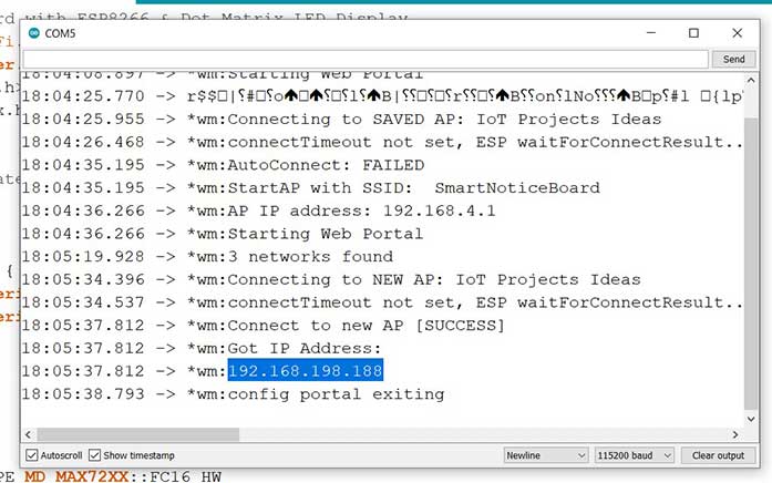
Now let us test the working and demo of the smart notice board. After uploading the code. You can open the serial monitor.
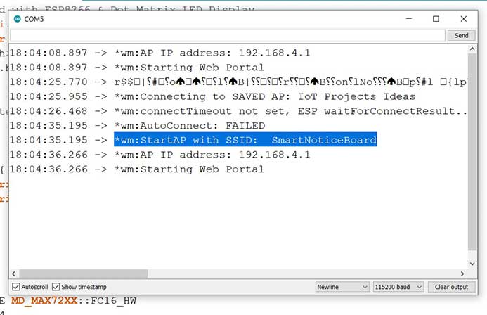
There you will see WiFi manager auto-connect failed and AP mode is enabled on NodeMCU.
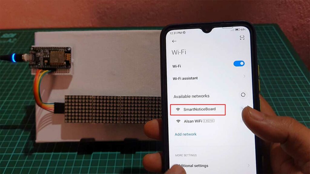
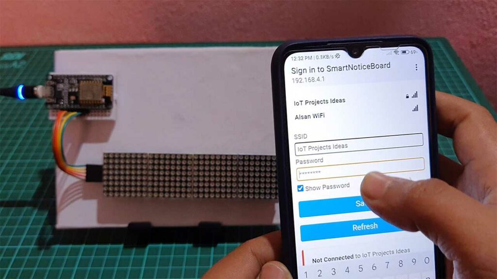
Now connect to this “SmartNoticeBoard“ WiFi Access point. You will see a sign-in popup notification.
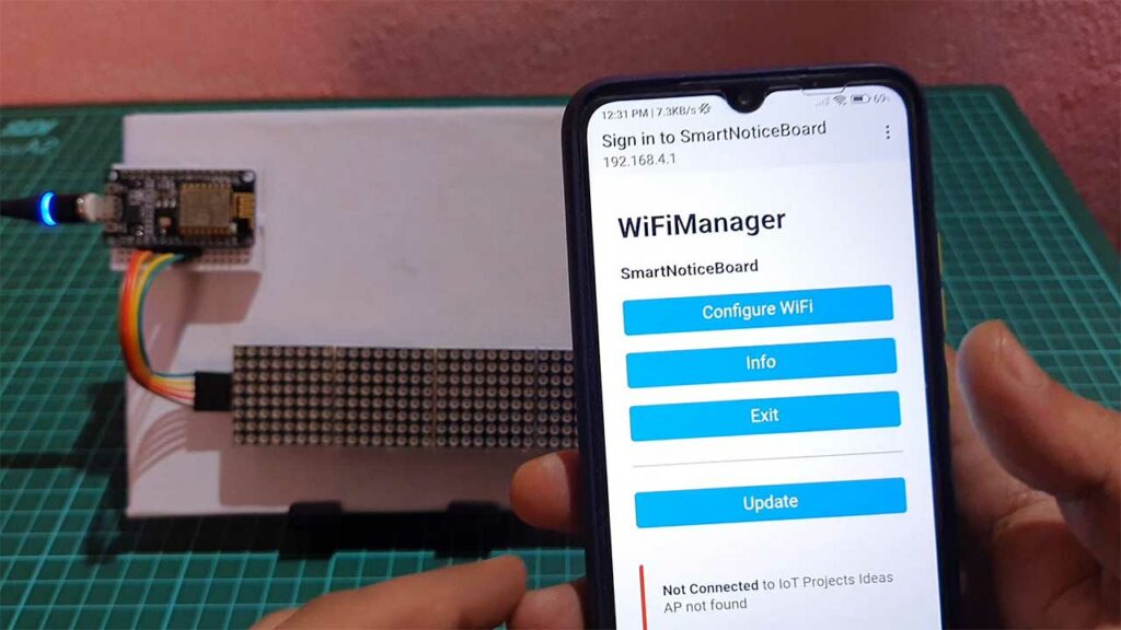
Click on it and Configure the WiFi credentials. You will also see Your WiFi Name on Top if it is not hidden. Now Enter your WiFi password and click on save.
The ESP8266 will connect to the Wi-Fi network using the Wi-Fi credentials. The dot matrix LED display will show the IP address after a successful connection.
You can open this IP address on your PC as well as the mobile phone connected to the same WiFi. open your web browser and insert the IP address.
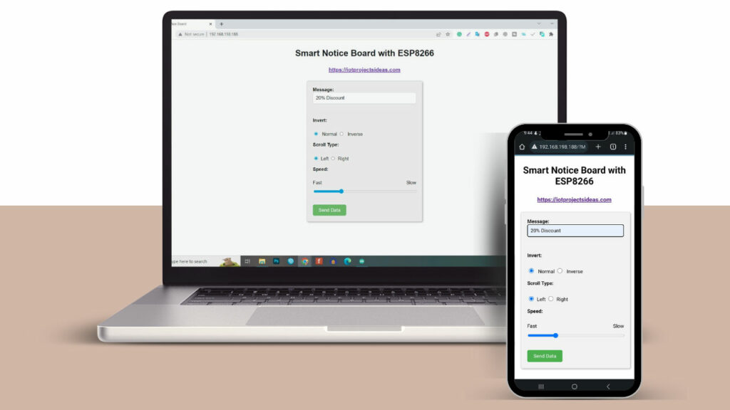
The browser will display the following page. From the web page enter any message you want to display on the dot matrix display as a notice then hit the send button.
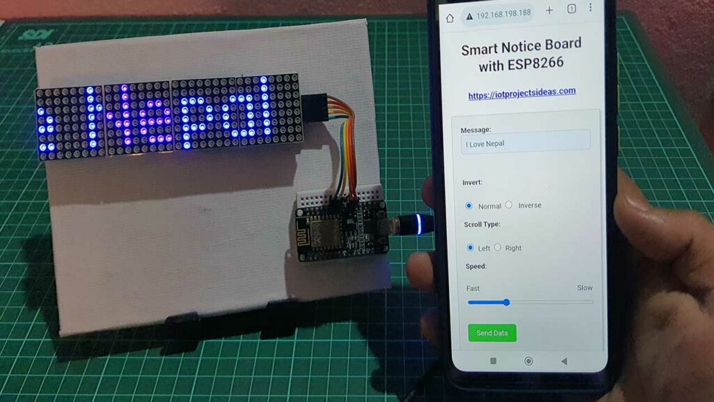
The dot matrix will show you the message in a few seconds. You can change the scrolling effect from left to right or from right to left. You can also change the scrolling speed and reverse the LED display.
Conclusion
The Smart Notice Board is a dynamic and versatile solution for displaying important messages and announcements. With the integration of the ESP8266 microcontroller and the dot matrix LED display, the Smart Notice Board offers a user-friendly and effective way to display information. The code and hardware required to create a Smart Notice Board are relatively simple and straightforward, making it an ideal project for beginners and hobbyists.

Hi, This is awesome, Will it work with the ESP32 as well?
You will at least change “ESP8266WiFi.h” to “WiFi.h”
Yes, It works but you need to change ESP8266 compatible library to ESP32 compatible library. Minor changes to the code can fix it.
Hello. Nice project, thanks a lot for sharing! I’d love to try it but I only have ESP32 board and my coding skills aren’t that good to make changes in the original code. Could you please point out what exactly need to be changed in the order to make this code work on ESP32 boards. Thank you.
Hi, I have done everything as shown in the video but I get nothing on the display not even the IP address ? Can anyone help me ?
Thanks for amazing project.
Lindly tell me one thing how can i set password for wifi. please guide.
Thanks and regards
Hi, installed all as described, and in IDE monitor I see following:
begin: exit
*wm:AutoConnect
*wm:Connecting to SAVED AP: telenet-5EBE8
*wm:connectTimeout not set, ESP waitForConnectResult…
*wm:AutoConnect: SUCCESS
*wm:STA IP Address: 192.168.1.145
But when I go to that IP, it tells me “This page is not working”, No response.
Any idea?
Thanks
I’ve got it working now, Was pointing to a wrong SSID.
I have other question,
How to change code using two max7219 display units ( totally 8 devices)
I changed that parameter in the code but doesn’t make a difference as both units are showing the same data while it should scroll over the full length of the 2 units.
Hope you can help me.
@Johan – change MAX_DEVICES from 4 to 8
#define MAX_DEVICES 8
The IP address shows a leading zero. eg 192.168.20.48 displays as 192.168.020.048. Browser won’t handle the 020.048 & commences a google search. Needs to be idiot proof for people who don’t understand IP addresses. How do I get it to display the IP address without the padding in the last two numbers so they show as 2 digits or 3 digits as required.
eg. 020.048 shows as 20.48 but if required 120.140 would show as 120.140
Also, what in the HTML controls the size of the message input box?
I’ve played with a couple of guesses. Box needs to be big enough to display a long message. Entry allows for 255 characters. Be good if the box was deeper and just word wrapped.
DJ
How can we find the password of wifi