Power Supply board for NodeMCU ESP8266
Power Supply for NodeMCU with Battery Charger & Boost Converter
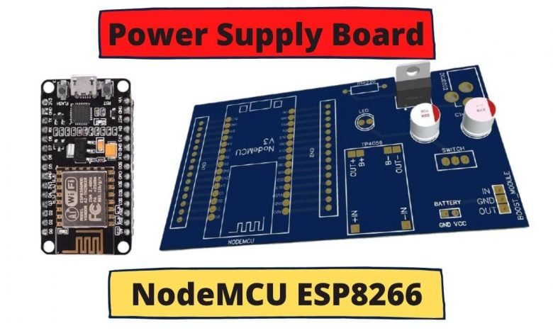
Overview: Power Supply board for NodeMCU
In this tutorial, we will make a Power Supply board for NodeMCU ESP8266. Here, we will use a battery boost converter circuit to operate the NodeMCU with a 3.7V battery. Obviously, the battery gets discharge after using it for a long time. So, we need to integrate a battery charging circuit that has a built-in battery management system. This will protect your battery from over-charging and over-discharging, so the battery lasts longer.
Most of the lithium-ion batteries found in the market come with 3.7V and 4.2V when fully charged. This is not enough to power up the NodeMCU Board. So we need to convert the voltage of the battery to 5V. For this reason, we are using a small boost converter module. Which is made using some inductors, IC & resistor. Similarly, the TP4056 Battery Charger Module is used to charge and manage the battery.
Besides this, if you don’t want to power the NodeMCU board using the battery, you can use the DC Power Adapter. we can power this board using a 9V/12V DC Adapter. The LM7805 Voltage regulator IC will limit the voltage up to 5V only.
Components Required
Following are the components required for making this Power Supply board for NodeMCU ESP8266. We can easily purchase all the components from Amazon. We provided the component purchase link below.
| S.N | Components Name | Quantity | |
|---|---|---|---|
| 1 | NodeMCU ESP8266 Development Board | 1 | https://amzn.to/3zRiok7 |
| 2 | TP4056 Charging Module | 1 | https://amzn.to/3yfP5Hp |
| 3 | LM7805 5V Voltage Regulator IC | 1 | https://amzn.to/3yFDUIp |
| 4 | Female DC Power Jack | 1 | https://amzn.to/2VG1AOF |
| 5 | 3.7V to 5V Boost Converter Module | 1 | https://amzn.to/3sblEUF |
| 6 | 3 Pin SPDT Switch | 1 | https://amzn.to/3iG3zei |
| 7 | Electrolytic Capacitor 470uF, 25V | 1 | https://amzn.to/3fWx3Tt |
| 8 | Electrolytic Capacitor 100uF,16V | 1 | https://amzn.to/2VG2gDH |
| 9 | 18650 Lithium Ion Battery | 1 | https://amzn.to/3iafIrL |
| 10 | 5mm LED Any Color | 1 | https://amzn.to/3CIZ36U |
| 11 | 220 ohm resistor | 1 | https://amzn.to/3zML4dX |
Power Required By NodeMCU
NodeMCU ESP8266 operates at 5V & 3.3V. It has an onboard LDO voltage regulator to keep the voltage steady at 3.3V. We can power NodeMCU using a Micro USB jack as well as a VIN pin (External Power Supply Pin).
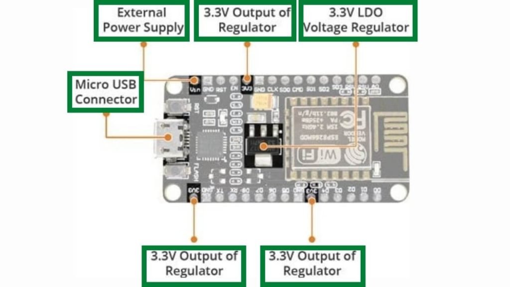
The NodeMCU requires 600mA power, as ESP8266 pulls around 80mA during RF transmission. For boot and Wi-Fi operation, it draws up to 200mA peak current. Thus supply power from Micro-USB Cable is not enough for NodeMCU Board when we are adding multiple sensors or modules to the Board. Basically, a Computer USB port can provide around 500mA of current. You can check more about NodeMCU Power requirements in these Datasheets.
3.7V to 5V Step-Up Boost Converter Module
The DC-DC step-up boost converter module provides 5V output at various input ranges from 1.5V to 5V. This simple and small module boosts the voltage level and provides the stabilized 5V output. This module operates at a frequency of 150KHZ. So, for the different input ranges, it consumes a different amount of current to produce a balanced output.
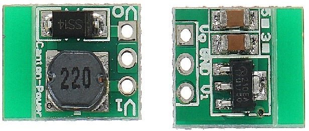
- Input 1-1.5V, output 5V 40-100mA
2. Input 1.5-2V, output 5V 100-150mA
3. Input 2-3V, output 5V 150-380mA
4. Input more than 3V, output 5V 380-480mA
Also read:
- Battery Status Monitoring System using ESP8266 & Arduino IoT Cloud
- Temperature Controlled Home Automation using Arduino
- IoT based Silent Intruder Alarm using Arduino
- How 555 IC works in Astable Operation & Monostable Operation
- IoT based Fire Detector & Automatic Extinguisher using NodeMCU
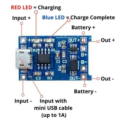
TP4056 Battery Charging Module
TP4056 is a charging module used for charging 3.7V rechargeable lithium batteries using the constant-current/constant-voltage (CC/CV) charging method. Besides safely charging, TP4056 BMS Board protects lithium batteries. The TP4056 module is suitable for both USB power and adapter power supplies. Because of the anti-reverse charging path, no external isolation diodes are required.
To learn more about this TP4056 module, you can go through its datasheet here: TP4056 Module Datasheet.
Power Supply Circuit for NodeMCU ESP8266 with Charger & Boost Converter
The Circuit Diagram for the Power Supply board for NodeMCU ESP8266 with Battery Charger & Boost converters is given below. We can power the circuit using two methods, one with a 9V/12V DC Adapter and the other with 3.7V Lithium-Ion Battery.
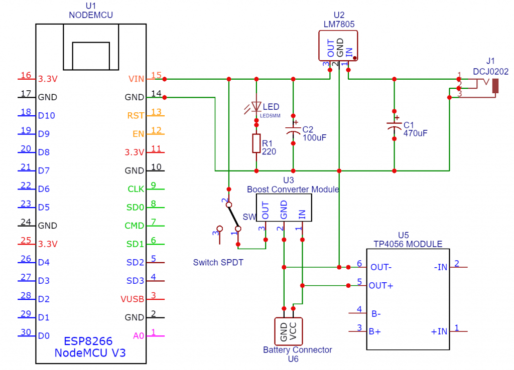
For powering the Board using DC Jack, we have used DCJ0202 Female Jack. We used 470uF & 100uF Electrolytic capacitors to avoid DC fluctuations. It also helps to remove voltage spikes. In an LM7805 Voltage regulator IC, we can input voltage from 7V to 35V. But I recommend using up to 15V only. Higher voltage dissipates more heat and requires a bigger heat sink. We connected the output from the Voltage regulator to the Vin pin of NodeMCU & GND to GND. Hence, you can power up the module using a 9V/12V DC Adapter or by 9V Battery.
If you don’t want to power up the NodeMCU ESP8266 using DC Adapter, you can use any 3.7V rechargeable battery. The Boost Converter Module boosts the 3.7V to 5V (can work from 2.8V input to 4.2V input). The 5V boosted voltage is connected to the switch, and we connected the switch to the 5V (Vin) pin of NodeMCU. We also connected the Battery terminal to the output terminal of the TP4056 Battery Charger Module. Thus, the battery can be charged using a 5V Micro-USB Data Cable.
The board has an LED connected via a 220-ohm resistor which is used to show the Module is powered ON. While charging the battery; I recommend it to turn off the SPDT switch.
PCB Designing
This is the PCB for the Power Supply board for NodeMCU ESP8266 with Battery Charger & Booster.
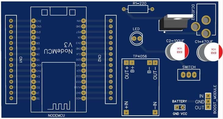
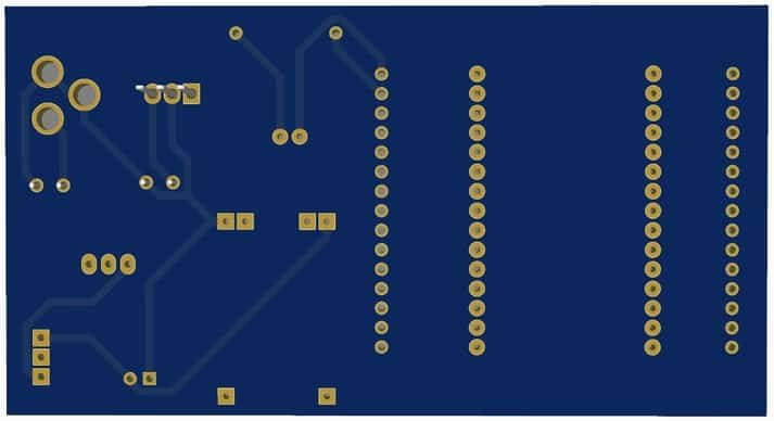
We designed the PCB using the EasyEDA PCB Designing tool. The front view & the back view of the PCB is given below.
I provided the Gerber File for the PCB below. You can download the Gerber File & go for PCB ordering.
Now you can visit the PCBWay official website by clicking here: https://www.pcbway.com/. So it will direct you to the PCBWay website.
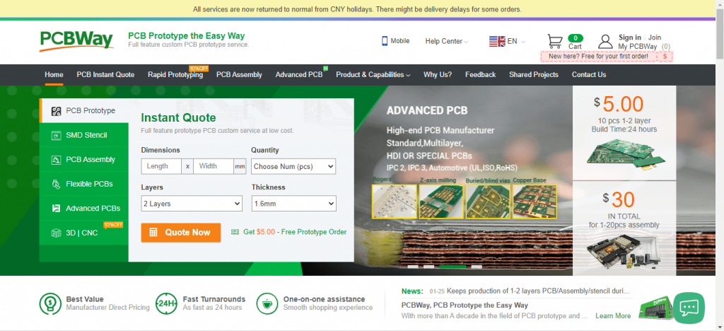
You can now upload the Gerber File to the Website and place an order. The PCB quality is very good. That is why most people trust PCBWay for PCB & PCBA Services.


Hello,
I am not clear on why you use a single pole double throw switch. Wouldn’t a single pole single throw switch work as well?
Thank You