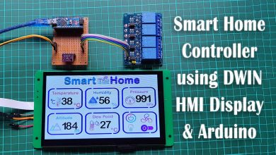
Fingerprint Door Lock Security Systems Using Arduino & LCD
Biometric Door Lock Security System Using Arduino
Overview: Fingerprint Door Lock Security using Arduino
In today’s tutorial, we are thrilled to present an exciting project that combines the power of Arduino and fingerprint technology. Get ready to dive into the world of Fingerprint Door Lock Security Systems Using Arduino & LCD.
Before we jump into the details, let’s start with a quick overview of the project and its objectives. Our goal is to create a simple and reliable security system that utilizes the R307 fingerprint sensor module, along with an Arduino board and an LCD display. This system will provide enhanced security features and streamline access control in various settings, such as homes, offices, and more.
Components Required
To bring this project to life, we’ll need a few key components. Here’s what we’ll be using:
| S.N | COMPONENTS NAME | QUANTITY | PURCHASE LINKS |
|---|---|---|---|
| 1 | Arduino Nano | 1 | Amazon | AliExpress |
| 2 | R307 Fingerprint Sensor | 1 | Amazon | AliExpress |
| 3 | 16x2 I2C LCD Display | 1 | Amazon | AliExpress |
| 4 | 12V Solenoid Lock | 1 | Amazon | AliExpress |
| 5 | Single channel 5V Relay Module | 1 | Amazon | AliExpress |
| 6 | Breadboard | 1 | Amazon | AliExpress |
| 7 | Jumper Cables | 20 | Amazon | AliExpress |
- Arduino board: The brain of our system, responsible for controlling and managing the different components.
- R307 fingerprint sensor module: A feature-packed biometric reader that enables secure fingerprint authentication.
- LCD display: We’ll use a 16×2 I2C LCD module to provide a user-friendly interface and display relevant information.
- Relay Module: To control electronic lock.
- Solenoid lock: This electromechanical lock will be triggered to unlock the door upon successful fingerprint verification.
- Jumper wires and breadboard: Essential for making connections between the components.
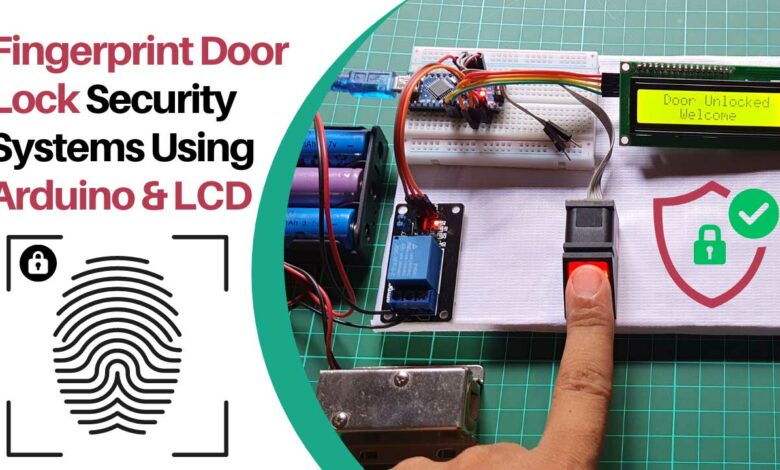
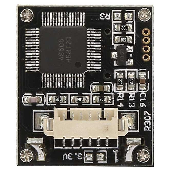
R307 Fingerprint Sensor Module
The R307 fingerprint sensor module is an affordable biometric reader module designed for easy integration with microcontrollers such as Arduino and Raspberry Pi.
Featuring a built-in fingerprint recognition algorithm, this module can be programmed with just a few lines of code to perform functions like matching, verifying, searching, or storing fingerprint data. For more information on how to interface the R307 Fingerprint Sensor with Arduino, please refer to our previous post.
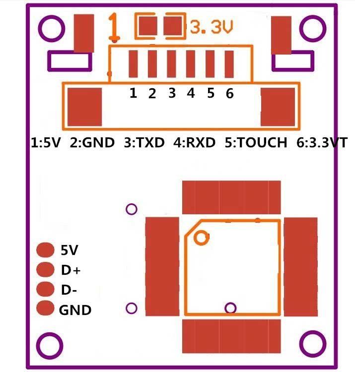
Pinout of R307 Fingerprint Sensor
The R307 fingerprint sensor module consists of 6 pins. But we only use 4 of them for communication and power supply. The following diagram illustrates the pinout configuration of the R307 fingerprint sensor.
R307 Fingerprint Sensor Module Specs
Here are some specifications of the R307 fingerprint sensor module:
- Interface: UART (TTL)
- Operating voltage: 3.6V – 6.0V DC
- Fingerprint image resolution: 500dpi
- False acceptance rate (FAR): <0.001% (security level 3)
- False rejection rate (FRR): <1.0% (security level 3)
- Identification speed: <0.5s
- Template storage capacity: up to 1000 templates
- Operating temperature: -20°C to +50°C
- Operating humidity: 40% RH – 85% RH
- Dimensions: 54mm x 20mm x 22mm
Schematic Diagram – Fingerprint Door Lock Security Systems Using Arduino & LCD
Moving on to the circuit diagram, let’s see how all the components are connected. The connections are fairly straightforward and will be as follows:
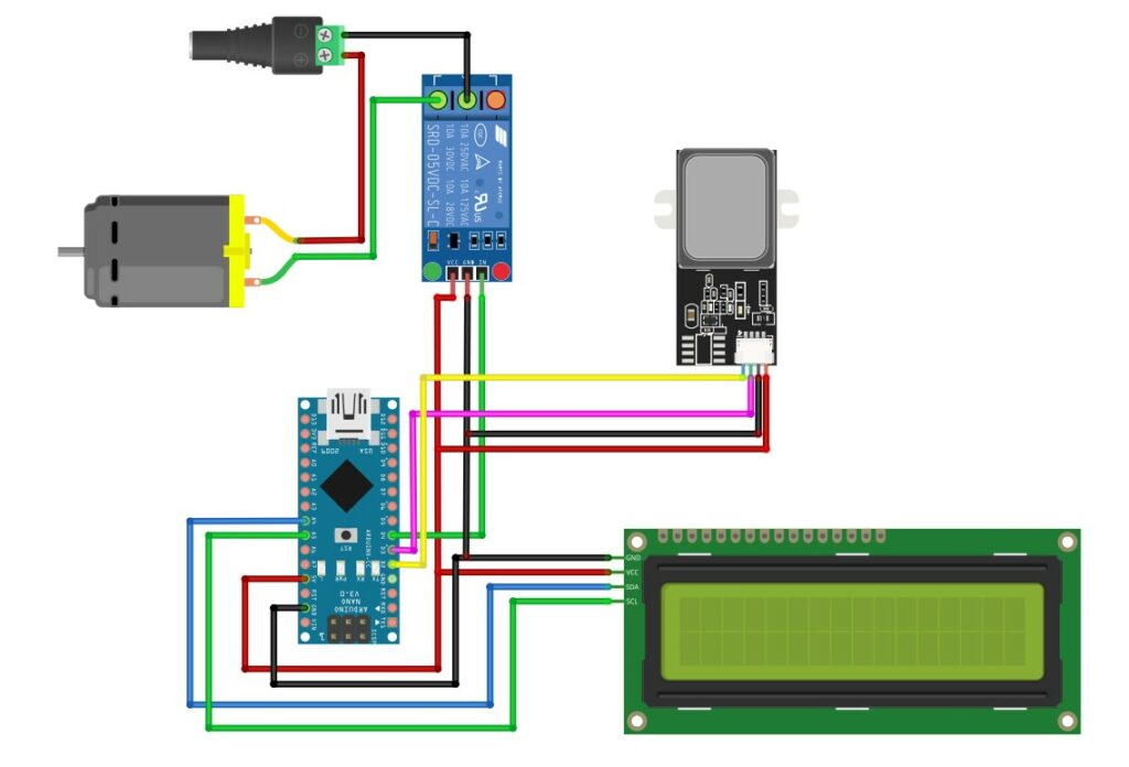
- VCC pin of the fingerprint sensor to the 5V pin on the Arduino
- GND pin of the fingerprint sensor to the GND pin on the Arduino
- TX pin of the fingerprint sensor to digital pin D2 on the Arduino
- RX pin of the fingerprint sensor to digital pin D3 on the Arduino
- Relay Pin to digital pin D4
- LCD SDA pin to Arduino Analog Pin 4
- LCD SCL pin to Arduino Analog Pin 5
- LCD VCC pin to Arduino 5V
- LCD GND pin to Arduino GND
Project PCB Gerber File & PCB Ordering Online
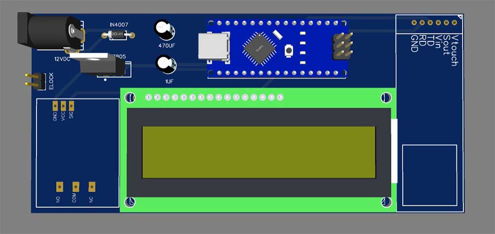
If you don’t want to assemble the circuit on a zero PCB and you want PCB for the project, then here is the PCB for you. The PCB Board for this project looks something like below.
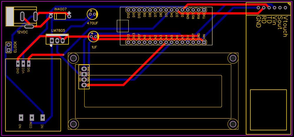
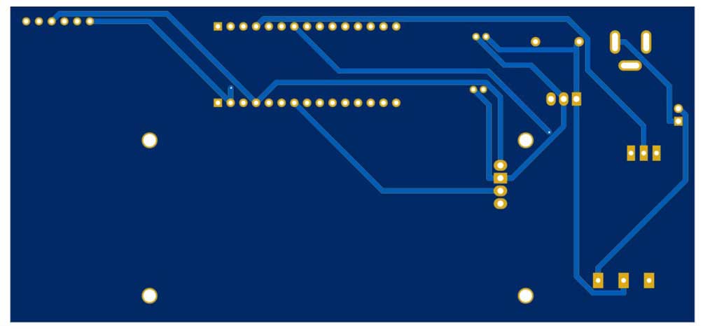
The Gerber File for the PCB is given below. You can simply download the Gerber File and order the PCB from PCBWay.com.
Now you can visit the PCBWay official website by clicking here: PCBWay.com. So you will be directed to the PCBWay website.

You can now upload the Gerber File to the Website and place an order. The PCB quality is superb & high standard. That is why most people trust PCBWay for PCB & PCBA Services. PCBWay is a leading manufacturer of high-quality PCBs and offers a wide range of services, including PCB fabrication, assembly, and components sourcing.
Arduino Code & Library
Begin by downloading the Adafruit Fingerprint library from the Arduino IDE Library Manager. For detailed instructions, refer to the tutorial titled “Fingerprint Sensor With Arduino.“
Open the Arduino IDE, navigate to File > Examples > Adafruit Fingerprint > enroll, and upload the code to your Arduino.
Fingerprint Enrollment Arduino Code
Below is a sample code for enrolling fingerprints with the R307 Fingerprint Sensor:
#include <Adafruit_Fingerprint.h>


#if (defined(__AVR__) || defined(ESP8266)) && !defined(__AVR_ATmega2560__)
// For UNO and others without hardware serial, we must use software serial...
// pin #2 is IN from sensor (GREEN wire)
// pin #3 is OUT from arduino  (WHITE wire)
// Set up the serial port to use softwareserial..
SoftwareSerial mySerial(2, 3);

#else
// On Leonardo/M0/etc, others with hardware serial, use hardware serial!
// #0 is green wire, #1 is white
#define mySerial Serial1

#endif


Adafruit_Fingerprint finger = Adafruit_Fingerprint(&mySerial);

uint8_t id;

void setup()
{
  Serial.begin(9600);
  while (!Serial);  // For Yun/Leo/Micro/Zero/...
  delay(100);
  Serial.println("nnAdafruit Fingerprint sensor enrollment");

  // set the data rate for the sensor serial port
  finger.begin(57600);

  if (finger.verifyPassword()) {
    Serial.println("Found fingerprint sensor!");
  } else {
    Serial.println("Did not find fingerprint sensor :(");
    while (1) { delay(1); }
  }

  Serial.println(F("Reading sensor parameters"));
  finger.getParameters();
  Serial.print(F("Status: 0x")); Serial.println(finger.status_reg, HEX);
  Serial.print(F("Sys ID: 0x")); Serial.println(finger.system_id, HEX);
  Serial.print(F("Capacity: ")); Serial.println(finger.capacity);
  Serial.print(F("Security level: ")); Serial.println(finger.security_level);
  Serial.print(F("Device address: ")); Serial.println(finger.device_addr, HEX);
  Serial.print(F("Packet len: ")); Serial.println(finger.packet_len);
  Serial.print(F("Baud rate: ")); Serial.println(finger.baud_rate);
}

uint8_t readnumber(void) {
  uint8_t num = 0;

  while (num == 0) {
    while (! Serial.available());
    num = Serial.parseInt();
  }
  return num;
}

void loop()                     // run over and over again
{
  Serial.println("Ready to enroll a fingerprint!");
  Serial.println("Please type in the ID # (from 1 to 127) you want to save this finger as...");
  id = readnumber();
  if (id == 0) {// ID #0 not allowed, try again!
     return;
  }
  Serial.print("Enrolling ID #");
  Serial.println(id);

  while (!  getFingerprintEnroll() );
}

uint8_t getFingerprintEnroll() {

  int p = -1;
  Serial.print("Waiting for valid finger to enroll as #"); Serial.println(id);
  while (p != FINGERPRINT_OK) {
    p = finger.getImage();
    switch (p) {
    case FINGERPRINT_OK:
      Serial.println("Image taken");
      break;
    case FINGERPRINT_NOFINGER:
      Serial.println(".");
      break;
    case FINGERPRINT_PACKETRECIEVEERR:
      Serial.println("Communication error");
      break;
    case FINGERPRINT_IMAGEFAIL:
      Serial.println("Imaging error");
      break;
    default:
      Serial.println("Unknown error");
      break;
    }
  }

  // OK success!

  p = finger.image2Tz(1);
  switch (p) {
    case FINGERPRINT_OK:
      Serial.println("Image converted");
      break;
    case FINGERPRINT_IMAGEMESS:
      Serial.println("Image too messy");
      return p;
    case FINGERPRINT_PACKETRECIEVEERR:
      Serial.println("Communication error");
      return p;
    case FINGERPRINT_FEATUREFAIL:
      Serial.println("Could not find fingerprint features");
      return p;
    case FINGERPRINT_INVALIDIMAGE:
      Serial.println("Could not find fingerprint features");
      return p;
    default:
      Serial.println("Unknown error");
      return p;
  }

  Serial.println("Remove finger");
  delay(2000);
  p = 0;
  while (p != FINGERPRINT_NOFINGER) {
    p = finger.getImage();
  }
  Serial.print("ID "); Serial.println(id);
  p = -1;
  Serial.println("Place same finger again");
  while (p != FINGERPRINT_OK) {
    p = finger.getImage();
    switch (p) {
    case FINGERPRINT_OK:
      Serial.println("Image taken");
      break;
    case FINGERPRINT_NOFINGER:
      Serial.print(".");
      break;
    case FINGERPRINT_PACKETRECIEVEERR:
      Serial.println("Communication error");
      break;
    case FINGERPRINT_IMAGEFAIL:
      Serial.println("Imaging error");
      break;
    default:
      Serial.println("Unknown error");
      break;
    }
  }

  // OK success!

  p = finger.image2Tz(2);
  switch (p) {
    case FINGERPRINT_OK:
      Serial.println("Image converted");
      break;
    case FINGERPRINT_IMAGEMESS:
      Serial.println("Image too messy");
      return p;
    case FINGERPRINT_PACKETRECIEVEERR:
      Serial.println("Communication error");
      return p;
    case FINGERPRINT_FEATUREFAIL:
      Serial.println("Could not find fingerprint features");
      return p;
    case FINGERPRINT_INVALIDIMAGE:
      Serial.println("Could not find fingerprint features");
      return p;
    default:
      Serial.println("Unknown error");
      return p;
  }

  // OK converted!
  Serial.print("Creating model for #");  Serial.println(id);

  p = finger.createModel();
  if (p == FINGERPRINT_OK) {
    Serial.println("Prints matched!");
  } else if (p == FINGERPRINT_PACKETRECIEVEERR) {
    Serial.println("Communication error");
    return p;
  } else if (p == FINGERPRINT_ENROLLMISMATCH) {
    Serial.println("Fingerprints did not match");
    return p;
  } else {
    Serial.println("Unknown error");
    return p;
  }

  Serial.print("ID "); Serial.println(id);
  p = finger.storeModel(id);
  if (p == FINGERPRINT_OK) {
    Serial.println("Stored!");
  } else if (p == FINGERPRINT_PACKETRECIEVEERR) {
    Serial.println("Communication error");
    return p;
  } else if (p == FINGERPRINT_BADLOCATION) {
    Serial.println("Could not store in that location");
    return p;
  } else if (p == FINGERPRINT_FLASHERR) {
    Serial.println("Error writing to flash");
    return p;
  } else {
    Serial.println("Unknown error");
    return p;
  }

  return true;
}
Once the upload is complete, open the Serial Monitor in the Arduino IDE. Set the baud rate to “9600” in the Serial Monitor.
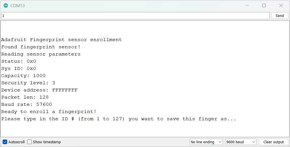
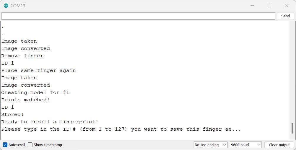
In the Serial Monitor, you will see the prompt “Enroll Fingerprint”. Follow the instructions displayed in the Serial Monitor:
- Set the Finger Print ID number according to the code.
- Place an enrolled finger on the sensor.
- Place the finger again on the sensor for confirmation.
After successfully enrolling the fingerprint, you can proceed to the final code.
By following these steps, you will be able to enroll fingerprints and test for a match using the R307 Fingerprint Sensor with Arduino.
Fingerprint Door Lock System Arduino Code
Once the fingerprints have been registered and enrolled. You can proceed with uploading the Source code for the Fingerprint door lock system on your Arduino board.
#include <Adafruit_Fingerprint.h>
#include <Wire.h>
#include <LiquidCrystal_I2C.h>
SoftwareSerial mySerial(2, 3); //Serial Communications


LiquidCrystal_I2C lcd(0x27, 16, 2);


Adafruit_Fingerprint finger = Adafruit_Fingerprint(&mySerial);

#define Relay 4

void setup()
{
  Serial.begin(9600);
  lcd.init();
  lcd.backlight();

  finger.begin(57600);
  pinMode(Relay, OUTPUT);
  digitalWrite(Relay, HIGH);
  delay(5);

  if (finger.verifyPassword()) {

    lcd.setCursor(0,0);
    lcd.print("  Finger Print ");
    Serial.println("  Finger Print ");
    lcd.setCursor(0, 1);
    lcd.print("Sensor Connected");
    Serial.println("Sensor Connected");
    delay (3000);

  } else {
    lcd.setCursor(0,0);
    lcd.print("Unable to found   ");
    Serial.println("Unable to found   ");
    lcd.setCursor(0,1);
    lcd.print("Sensor");
    Serial.println("Sensor");
    delay(2000);

      lcd.setCursor(0, 0);
    lcd.print("Please Check    ");
    Serial.println("Please Check    ");
    lcd.setCursor(0,1);
    lcd.print("  Sensor Wiring ");
    Serial.println("  Sensor Wiring ");
    while (1) {
    delay(1); }
  }


}

void loop()
{
  lcd.setCursor(0,0);
  lcd.print("Place finger...");
  Serial.println("Place finger...");
  lcd.setCursor(0,1);
  lcd.print("   start scan    ");
  Serial.println("   start scan    ");
  getFingerprintID();
  delay(50);            //don't ned to run this at full speed.
}

uint8_t getFingerprintID() {
  uint8_t p = finger.getImage();
  if(p == FINGERPRINT_NOFINGER){
    return p;
  }
  else if(p != FINGERPRINT_OK){
    lcd.setCursor(0,0);
    lcd.print("Scan Error      ");
    Serial.println("Scan Error      ");
    lcd.setCursor(0,1);

    delay(2000);
    return p;
  }

  p = finger.image2Tz();
  if(p != FINGERPRINT_OK){
    lcd.setCursor(0,0);
    lcd.print("Processing Error");
    Serial.println("Processing Error");
    lcd.setCursor(0,1);
    lcd.print(" Try Again ");
    Serial.println(" Try Again ");
    return p;
  }
  p = finger.fingerSearch();
  if (p == FINGERPRINT_OK) {
    lcd.clear();
  lcd.setCursor(0, 0);
  lcd.print("  Door Unlocked");
  Serial.println("  Door Unlocked");
  lcd.setCursor(0, 1);
  lcd.print("    Welcome");
  Serial.println("    Welcome");

    digitalWrite(Relay,LOW);
    delay(5000);

  } else if (p == FINGERPRINT_PACKETRECIEVEERR) {
    lcd.setCursor(0,0);
    lcd.print("Comm Error      ");
    Serial.println("Comm Error      ");
    lcd.setCursor(0,1);
    lcd.print("                ");
    Serial.println("                ");
    delay(2000);
    return p;


  } else if (p == FINGERPRINT_NOTFOUND) {
    lcd.setCursor(0,0);
    lcd.print("Access Denied   ");
    Serial.println("Access Denied   ");
    lcd.setCursor(0,1);
    lcd.print("                ");
    delay(2000);
    return p;
  } else {
    lcd.setCursor(0,0);
    lcd.print("Error in matching");
    Serial.println("Error in matching");
    lcd.setCursor(0,1);
    lcd.print("Not Valid Finger");
    Serial.println("Not Valid Finger");
    delay(2000);
    return p;
  }
  digitalWrite(Relay,HIGH);
  return finger.fingerID;
}
Testing & Demo: Biometric Door Lock
To test and demonstrate the Biometric Fingerprint Door Lock project follow the steps:
- Set up the hardware and connect the Fingerprint Sensor and Arduino as shown in the circuit diagram.
- Copy the provided code to the Arduino IDE and install the necessary libraries.
- Upload the code to the Arduino board and open the Serial Monitor (baud rate: 9600).
- If the Fingerprint Sensor is connected successfully, the LCD will display “Fingerprint Sensor Connected.“
- Place your finger on the sensor to start the scan. The LCD and Serial Monitor display real-time feedback.
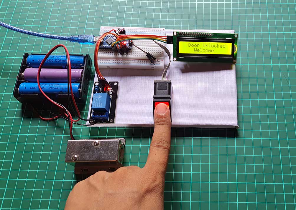
- If the fingerprint is recognized, the LCD shows “Door Unlocked” and triggers the relay for 5 seconds.
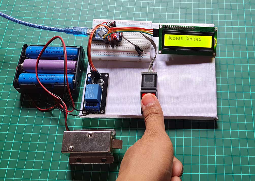
- The LCD and Serial Monitor will indicate any errors or unrecognized fingerprints.
- Repeat the process with different fingers to observe the matching results.
- Customize or add features based on your requirements.
Conclusion
In conclusion, our Fingerprint Door Lock Security Systems project offers a simple and convenient solution for access control. By combining the power of Arduino, the versatility of the R307 fingerprint sensor module, and the user-friendly LCD display, we’ve created a reliable and secure system. Feel free to modify and adapt the project to fit your specific requirements.
That’s all for today’s project! If you enjoyed it and found it helpful, don’t forget to give it a thumbs up and subscribe to our channel ‘IoT Projects Ideas’ for more exciting projects like this. Thanks for watching, and we’ll see you in the next video!