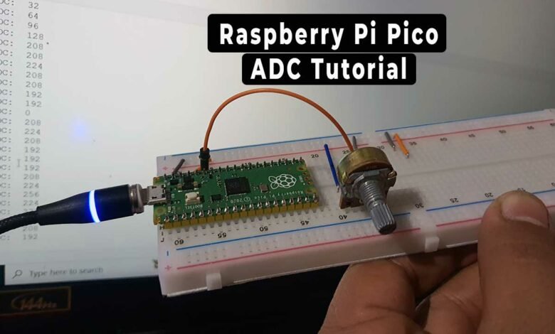
How to use ADC in Raspberry Pi Pico using MicroPython
ADC Tutorial in Raspberry Pi Pico using Potentiometer
This tutorial teaches how to use the analog-to-digital converter (ADC) feature on the Raspberry Pi Pico microcontroller board using MicroPython and an example code. An ADC is a circuit that converts a continuous analog voltage to a digital value that can be understood and used by digital devices for computation.
Overview
The Raspberry Pi Pico is built with the RP2040 microcontroller and has 26 multi-function GPIO pins out of 36 total. Among these 36 pins, there are 4 ADC pins, but only 3 of them are usable. The Pico’s ADC is 12-bits, which is 4 times more precise than the 10-bit ADC found on an Arduino board.
We will provide a MicroPython code to demonstrate how to use an ADC pin with an analog sensor. A potentiometer is a common tool for varying the input analog voltage. Before diving into the ADC guide, it is recommended to review the Raspberry Pi Pico Getting Started Tutorial to gain a better understanding of the module.
| S.N | COMPONENTS NAME | QUANTITY | PURCHASE LINKS |
|---|---|---|---|
| 1 | Raspberry Pi Pico Basic Starter Kit | 1 | Amazon | AliExpress |
What is Analog to Digital Converter (ADC)?
An Analog to Digital Converter (ADC) is a device that converts an analog voltage on a pin to a digital number. It enables the interface between the analog world and the digital world, allowing electronics to interact with the surrounding environment.
In real-world applications, an ADC system converts analog signals such as a sound picked up by a microphone or light entering a digital camera into digital signals. An ADC can also provide isolated measurements, like an electronic device that converts an input analog voltage or current to a digital number representing the magnitude of the voltage or current.
ADCs are particularly useful for sensors, allowing for the measurement of environmental parameters such as light, sound, distance, gravity, acceleration, rotation, smell, gases, and other particles.
How does an ADC work in a Microcontroller?
Most microcontrollers today have built-in ADC converters. It is also possible to connect an external ADC converter to any type of microcontroller. ADC converters typically have 10 or 12 bits, resulting in 1024 to 4096 quantization levels. A 16-bit ADC has 65536 quantization levels. The Raspberry Pi Pico has a 12-bit ADC with a quantization level of 4096.
The user program must initiate the ADC conversion process. Then it may take several hundred microseconds for the conversion to complete. ADC converters usually generate interrupts when a conversion is complete. It allows the user program to read the converted data as quickly as possible.
ADC in Raspberry Pi Pico
The Raspberry Pi Pico microcontroller board has four 12-bit SAR-based analog-to-digital converters (ADC). But only three of them can be used for analog channels. The fourth ADC channel is internally connected to the internal temperature sensor. This means that the internal temperature can be measured by reading the analog value of ADC4. The following table shows the input signal for ADC0, ADC1, and ADC2 can be connected to GP26, GP27, and GP28 pins respectively.
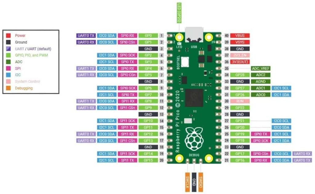
| ADC Module | GPIO Pins |
| ADC0 | GP26 |
| ADC1 | GP27 |
| ADC2 | GP28 |
The ADC module in the Pico supports conversion in polling, interrupt, and FIFO with DMA mode. The conversion speed per sample is 2μs, which is equivalent to 500kS/s. The RP2040 microcontroller operates on a 48MHz clock frequency which comes from USB PLL. Therefore, it takes 96 CPU clock cycles to perform one conversion. This means the sampling frequency is (96 x 1 / 48MHz) = 2 μs per sample (500kS/s).
Raspberry Pi Pico ADC Example Code
This example demonstrates how to use the analog-to-digital converter (ADC) feature on the Raspberry Pi Pico microcontroller board using MicroPython. To do this, we will use a 10K potentiometer to vary the analog input voltage. Then map it to a digital value between 0 and 3.3V using a 12-bit or 16-bit ADC.
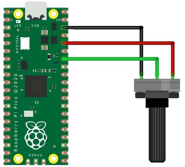
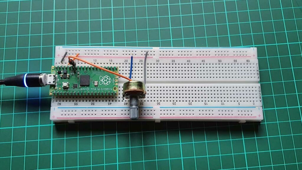
The connection diagram for this example is as follows: connect pin 1 and pin 3 of the potentiometer to the 3.3V pin and GND pin of the Raspberry Pi Pico, respectively. Connect pin 2 of the potentiometer to GP28 of the Raspberry Pi Pico.
To write and test this code, you can use the Thonny IDE or uPyCraft IDE. Copy the following code and hit the “Run button” or save the code as main.py on Raspberry Pi Pico.
import machine
import utime

analog_value = machine.ADC(28)

while True:
    reading = analog_value.read_u16()
    print("ADC: ",reading)
    utime.sleep(0.2)
In this code, the analog input is defined as connected to pin 28. A while True loop is created to create an infinite loop. Then, the ADC value is read using the read_u16 function and displayed on the shell monitor using the print function.
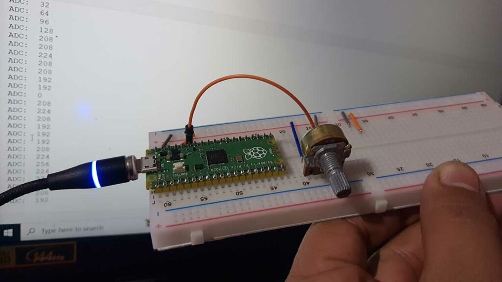
When you rotate the potentiometer, the value will range from 0 to 65536. which is unexpected because the value should range from 0 to 4096. This is because the ADC is supposed to be 12-bit, not 16-bit. Nevertheless, this is how you can read analog values using the ADC on the Raspberry Pi Pico.
Dear Sir, the explanation and everything is great, but…..
an lcd would be needed to display the values, assume you are working on a machine, the potentiometer is not working, we need to test it to see if he is the problem or something else