The BME280 is a widely used sensor that measures temperature, humidity, barometric pressure, dew point, and altitude. Today we are going to learn Interfacing of the BME280 Sensor with Arduino. It gives your Arduino project the ability to sense the surrounding environment with a BME280 sensor.
The BME280 sensor is relatively simple to use. It is pre-calibrated and you don’t require any extra components. So you can start measuring relative humidity, temperature, barometric pressure, approx. altitude, & dew point using Arduino and BME280 sensor.
Components Required
The following are the list of the components that are required for Interfacing BME280 Sensor with Arduino.
| S.N | Components Name | Description | Quantity | |
|---|---|---|---|---|
| 1 | Arduino UNO | ARDUINO UNO R3 | 1 | https://amzn.to/2L0iZf2 |
| 2 | BME280 | Barometric Pressure Sensor | 1 | https://amzn.to/38s2WPo |
| 3 | Jumper Wires | Male to Male Jumper Wires | 4 | https://amzn.to/2JWSR44 |
| 4 | USB 2.0 cable | USB 2.0 cable type A/B | 1 | https://amzn.to/3688OwF |
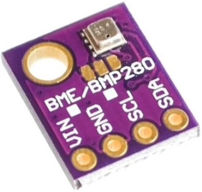
Introduction to BME280 Sensor
The BME280 sensor contains Bosch next-generation digital temperature, humidity, and pressure sensor. It is the successor of the sensors like BMP180, BMP280, or BMP183.
BME280 Sensor Measures
As I already mentioned above, The BME280 is a Five in one Environmental digital sensor that measures:
- Temperature
- Humidity
- Barometric pressure
- Altitude
- Dew Point
Accuracy and Operation Range of BME280 Sensor
The following table shows the Accuracy and operation range of the temperature, humidity, pressure, and altitude of the BME280 Sensor:
| Sensor | Accuracy | Operation Range |
| Temperature | +/- 1.0ºC | -40 to 85 ºC |
| Humidity | +/- 3% | 0 to 100 % |
| Pressure | +/- 1 hPa | 300 to 1100 hPa |
| Altitude | +/- 1 M | 0 – 30,000ft |
| Dew Point | +/- 1.5ºC | Depends on Temperature & Humidity |
Note: Dew Point is measured using temperature and relative humidity parameters. Through some mathematical calculations, the program returns the dew point in Celsius.
BME280 sensor specifications
- Power Requirement 3.3V or 5V (Module comes with built-in LM6206 3.3V regulator)
- Easy to interface with any microcontroller.
- The BME280 consumes less than 1mA during measurements.
- The module features an I2C communication protocol. So, it can be easily interfaced with any microcontroller of your choice.
- We can change the default I2C address of the BME280 module with the solder jumper beside the chip.
BME280 Sensor Pinout
The following table is the BME280 sensor Pinout table:
| VCC | Powers the sensor |
| GND | Ground Pin |
| SCL | SCL pin for I2C communication SCK pin for SPI communication |
| SDA | SDA pin for I2C communication SDI (MOSI) pin for SPI communication |
| SDO | SDO (MISO) pin for SPI communication |
| CSB | Chip select pin for SPI communication |
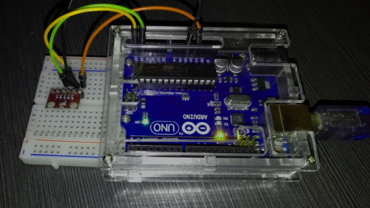
Interfacing BME280 Sensor with Arduino UNO
Now, Let’s wire the BME280 sensor with the Arduino. The Connections are fairly simple. Start by connecting the VIN pin to the 3.3V output on the Arduino and connect GND to the Ground Pin.
We use now the remaining SCL and SDA pins for I2C communication. Connect the SCL pin to A5 and the SDA pin to the A4 pin of Arduino, respectively.
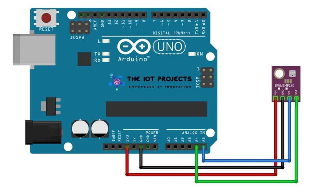
| BME280 | ARDUINO UNO |
| Vin | 3.3V |
| GND | GND |
| SCL | A5 |
| SDA | A4 |
Recommended Readings:
- Simple Weather station using Arduino & BME280 Barometric Pressure Sensor
- BME280 Based Mini Weather Station using ESP8266/ESP32
- Interface DHT11 Sensor with Arduino and LCD
Programming Code
To program the BME280 sensor with Arduino, we need the following libraries.
These two libraries make our program simple. We can just use a simple command to read the temperature, relative humidity, barometric pressure data, Dew point, and approx. Altitude data.
Installing Adafruit BME280 and Adafruit Unified Sensor Library
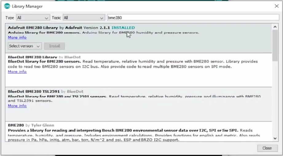
To install the library, navigate to the Sketch > Include Library > Manage Libraries… Wait some time for Arduino IDE to update the list of installed libraries.
Now in the search field search for “Adafruit BME280” and install the library as shown in the image below.
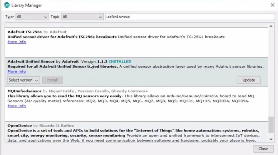
Again, search for “Adafruit Unified Sensor” and install that library as well.
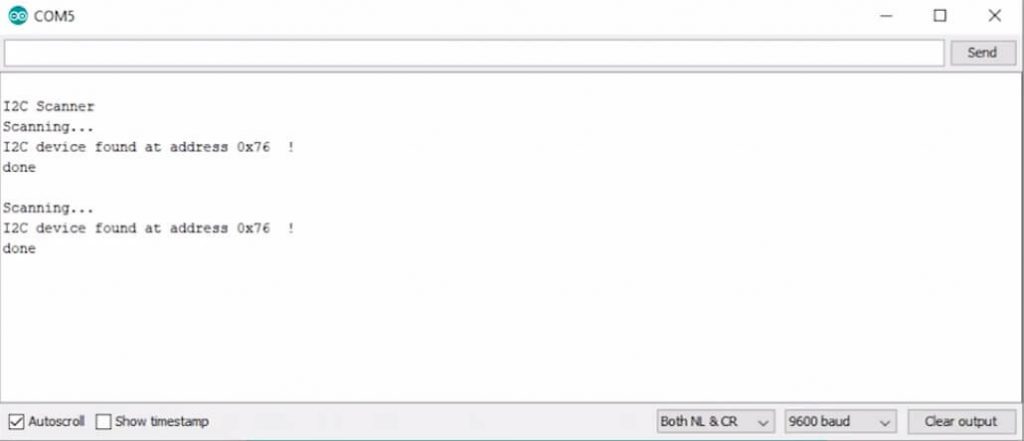
Check the Default I2C address for BME280 Sensor
To check the default I2C address of your BME280 sensor with Arduino. Simply upload the I2C Address Scanner code provided below. Now, open the serial monitor to check your BME280 default I2C address. This code will also help you to check your sensor working or not.
// I2C address Scanner code
 #include <wire.h>
 void setup()
 {
   Wire.begin();
 Serial.begin(9600);
   while (!Serial);             //  wait for serial monitor
   Serial.println("I2C Scanner");
 }
 void loop()
 {
   byte error, address;
   int nDevices;
 Serial.println("Scanning…");
 nDevices = 0;
   for (address = 1; address < 127; address++ )
   {
     // The i2c_scanner uses the return value of
     // the Write.endTransmisstion to see if
     // a device did acknowledge to the address.
     Wire.beginTransmission(address);
     error = Wire.endTransmission();
 if (error == 0) {   Serial.print("I2C device found at address 0x");   if (address < 16)     Serial.print("0");   Serial.print(address, HEX);   Serial.println("  !");   nDevices++; } else if (error == 4) {   Serial.print("Unknown error at address 0x");   if (address < 16)     Serial.print("0");   Serial.println(address, HEX); }
 }
   if (nDevices == 0)
     Serial.println("No I2C devices found");
   else
     Serial.println("done");
 delay(5000);           // wait 5 seconds for next scan
 }
Now copy the example program code of the BME280 sensor from below.
#include <Wire.h>
#include <Adafruit_Sensor.h>
#include <Adafruit_BME280.h>
#define SEALEVELPRESSURE_HPA (1013.25)
 Adafruit_BME280 bme; // For I2C interface
 void setup() {
   Serial.begin(9600);
   Serial.println(F("BME280 Sensor event test"));
   if (!bme.begin()) {
     Serial.println("Could not find a valid BME280 sensor, check wiring!");
     while (1);
   }
 }
 void loop() {
   Serial.print("Temperature = ");
   Serial.print(bme.readTemperature());
   Serial.println("*C");
   Serial.print("Pressure = ");
   Serial.print(bme.readPressure() / 100.0F);
   Serial.println("hPa");
   Serial.print("Humidity = ");
   Serial.print(bme.readHumidity());
   Serial.println("%");
   Serial.print("Approx. Altitude = ");
   Serial.print(bme.readAltitude(SEALEVELPRESSURE_HPA));
   Serial.println("m");
   double dewPoint = dewPointFast(bme.readTemperature(), bme.readHumidity());
   Serial.print("Dew point = ");
   Serial.print(dewPoint);
   Serial.println(" *C");
   Serial.println();
   delay(1000);
 }
 double dewPointFast(double celsius, double humidity)
 {
   double a = 17.271;
   double b = 237.7;
   double temp = (a * celsius) / (b + celsius) + log(humidity * 0.01);
   double Td = (b * temp) / (a - temp);
   return Td;
 }
Then upload the code to the Arduino. Now open the serial monitor. You can see the BME280 Sensor test is running. If you see the error message like: “Could not find a valid BME280 sensor, check wiring” then you need to change your BME280 default I2C address in the Adafruit_BME280.h file.
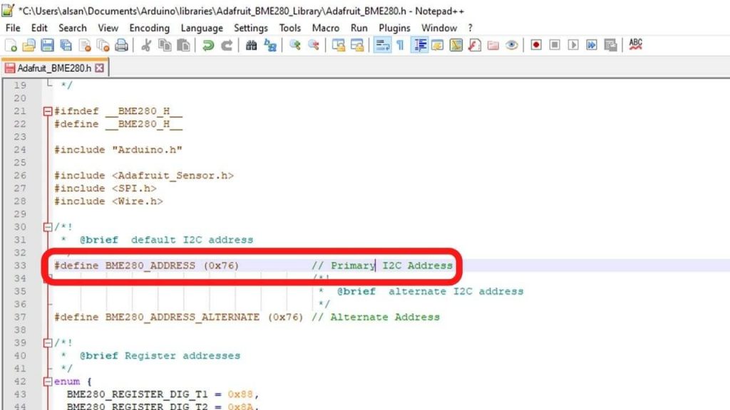
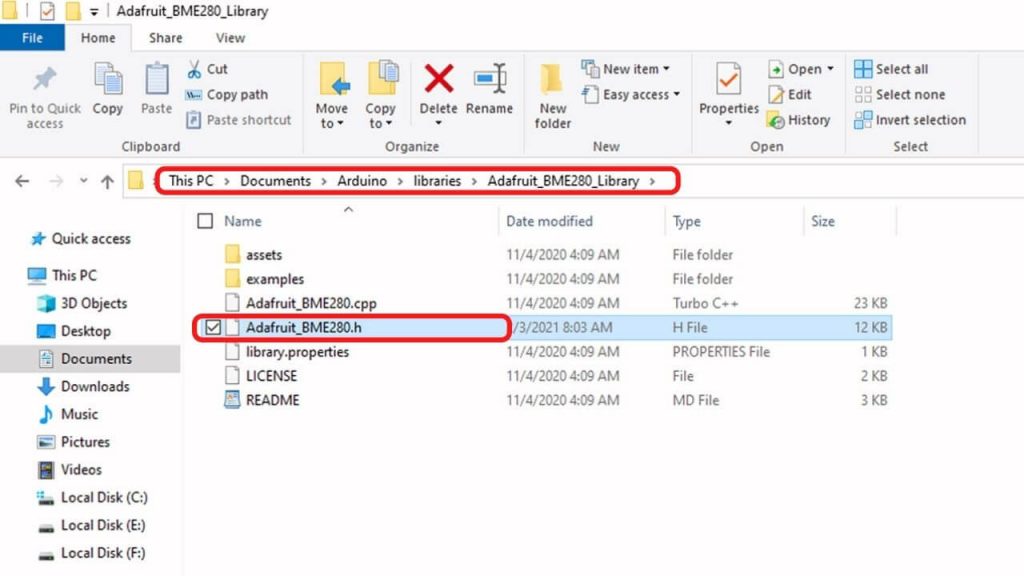
The Adafruit_BME280.h file located at: DocumentsArduinolibrariesAdafruit_BME280_Library. For reference, check the image below.
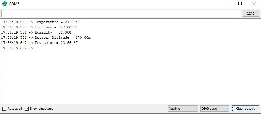
Now, re-upload the code and check your Serial Monitor. Finally, you got the temperature, relative humidity, barometric pressure data, approx. Altitude, and Dew Point data from the BME280 sensor using Arduino IDE.
Video Tutorial
Conclusion
So, that’s all for Interfacing BME280 Sensor with Arduino. I hope you found the tutorial useful. Now, which project do you like to see using the BME280 sensor module? Let me know in the comments below.