Introduction to The Internet Of Things (IoT)
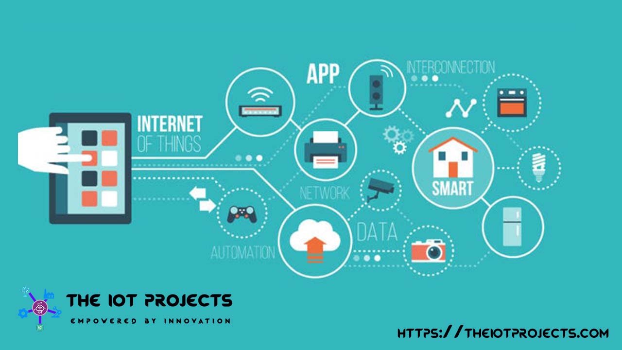
The IoT – Internet Of Things is the giant network of interconnected devices. These devices are capable of making decisions without any human interaction. “The IoT Projects” welcomes you to the fundamental concepts Session on the Internet Of Things which will help you to get started with IoT.
Before getting started with the concept, let’s have a look at our agenda. So we can start out with “Introducing you to the core concept of IoT”. Basically, here we are going to discuss ” Why do we need IoT?, What is IoT?, Benefits of IoT, and it’s Applications.
Introduction to IoT
So let’s get started what is the Internet of Things? In terms of IoT, any objects around you can become a “Things” that may be your Home Lights, Doors, Fridge, AC, Heater, Washing Machine or even a shower. That’s why it is often called the Internet Of Things (IoT) or Everythings.
Now to help you understand what is internet of things? Let’s have a look at an example of mobile phone forest.
OKAY…
Our Mobile phones has GPS tracking. It also has mobile Gyroscope. You have adaptive brightness which gets adjusted based on the light falling on it. Not only that, it has voice recognition and even face detection features. So, again there are lots of features that are coming to the mobile assets. Most of these have a common interaction between them. Because let’s say one application can use all of these features. I can also have these features in itself being interacting with each other. Let’s say based on a GPS location my brightness could be adjusted or based on the direction of my phone being held. The brightness in itself can also be adjusted as well. Hence, there are a lot of features. But, when they interact with each other these features come together to bring in a better system that anything they can provide individually. As such, that’s what the Internet Of Things(IoT) is it.
Basic example of IoT
Basically, it is a platform where we can connect everyday things which are embedded with either electronics software or sensors to the Internet. Finally, this in turn enables us to collect as well as exchange data between these things.
Now when I say things it can be anything and nothing. Let’s say I have an Internet Platform where I can connect these things. If I take the example of my House. I can connect by Door Lock, I can connect my AC, My Lights, etc.. and all these can be managed on the same platform. Since, I have a platform so I can also connect my car to this system. Finally, I can keep a track of my fuel meter. I can keep a track of my Speed Limit. As well as keep track of the location of the Car.
These are real world IoT Examples
Now, If there is a collective platform where all of these are connected. Wouldn’t it be great? Because, I would love to ON the AC and set a cool temperature at my home by the time I reach from My office. So, if I have a platform that knows my preference and that keeps track of where I Am and when I am going from work back to Home and my preference suggests that “it would be best if there was an easy temperature of about 22 or 23 degree centigrade”. This is something that is definitely possible through Internet Of Things. For more clearance, let’s have a look at this other examples:
let’s say you come back home from the office. Now, This would be great, If you wouldn’t even need a key to unlock your door. Your home system should be aware that you have came home and should unlock all the doors that are needed.
Yes, now this can be done if your mobile and your home devices are connected onto the same platform. Based on the location of your mobile,
It can identify that you are at home. Hence, it will automatically unlock the door and let you go inside as well.
These are some of the real world Applications of Internet of Things.These are something that are already happening. But going forward, what we need to understand is that when I have a specific component with me, which can do a lot individually. Wouldn’t it be great? If I can collaborate this complaint with my system of different components and build up at a system.
This is what the internet of things is helping us to. You provide a platform to which all these things are connected through the internet. So the internet becomes the medium through which you’re connecting all these components or things to a platform.
How does IoT works?
If you are thinking to create your own IoT system then you will need to know the basic working principle of IoT. The Internet Of Things Components are:
- Sensors
- Connectivity
- Processing
- User Interface (UI)
Sensors: It is used for collecting the information from their surroundings. These sensors may be standalone objects or a part of a device. A GPS tracker on automobiles would be an example.
Connectivity: So to communicate between these sensors and devices Internet or the IoT Network is needed. This can be done through a variety of methods available. Such as cellular data, Bluetooth, NFC, WiFi, etc. Actually these connections allows the sensors or devices to send and receive the data and instructions.
Processing: The data and information that are collected by the sensors needs to be processed and analyzed to allow the devices or users to take action over it. Actually these processing is done in cloud. In case of car GPS sensors, the data received will be processed to see if the car is within the desired range or Location.
User interface(UI): When the information are processed, they needs to be shared with the user through some medium. Again, this can be done in a variety of ways. Such as delivering SMS, Notifications to their Mobile Phones/Emails or Triggering Alarms etc. User Interface allows the user to monitor their network and initiate the required actions.
But in some cases the actions can be initiated without any human interaction. For example Mobile phones adaptive brightness. Here the sensors detects the light around it and automatically adjust the phone brightness.
Working Process of IoT in Short
Now in short: The sensors collect information and delivers this over the internet to process the data. The processor finalizes the data and sends back to the users. Now when the user gets information. The user decides what actions need to be taken. After that actuators receives the order actions which makes changes as per the user’s instructions.
Note: Actuators (Devices that convert electrical signals to Output actions)
In case of automated system, the processor sends instructions to actuators itself.

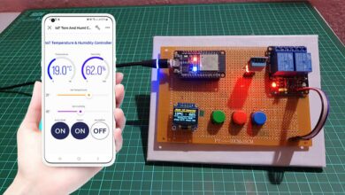
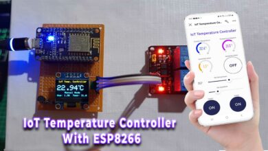
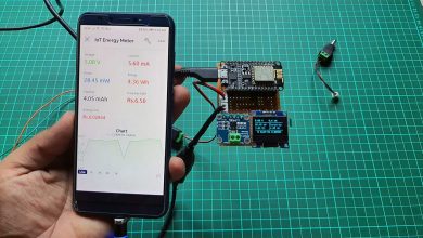
This future technology makes our living hood more easier than before. It is easy to connect with people and as well as machines. With the help of GPS technology, we’re able to track anyone from anywhere.
Thanks for sharing this blog!