Remote Serial Monitor for ESP8266 using WebSerial
Monitor Sensor Data Remotely using ESP8266 & WebSerial Library
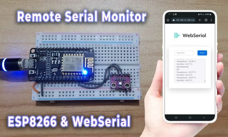
WebSerial is a powerful tool that allows us to remotely monitor and control our ESP8266-based projects through a web browser. In this blog post, we will explore how to set up a remote serial monitor for ESP8266 using WebSerial Library. We will use the popular NodeMCU ESP8266 development board along with the BME280 sensor to monitor temperature, humidity, pressure, and altitude. Let’s dive in!
Components Required
To build this project, you will need the following components:
- NodeMCU ESP8266 development board
- BME280 sensor
- Jumper wires
- Breadboard
You can purchase them from below:
| S.N | COMPONENTS NAME | QUANTITY | PURCHASE LINKS |
|---|---|---|---|
| 1 | NodeMCU ESP8266 Board | 1 | Amazon | AliExpress |
| 2 | BME280 Sensor | 1 | Amazon | AliExpress |
| 3 | Breadboard | 1 | Amazon | AliExpress |
| 4 | Jumper Cables | 5 | Amazon | AliExpress |
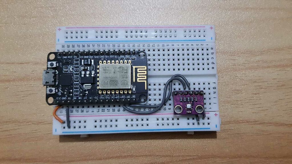
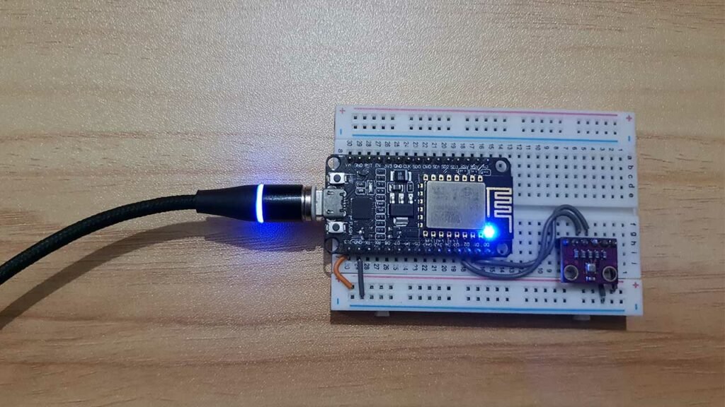
Interfacing BME280 Sensor with ESP8266
Connect the components as follows:
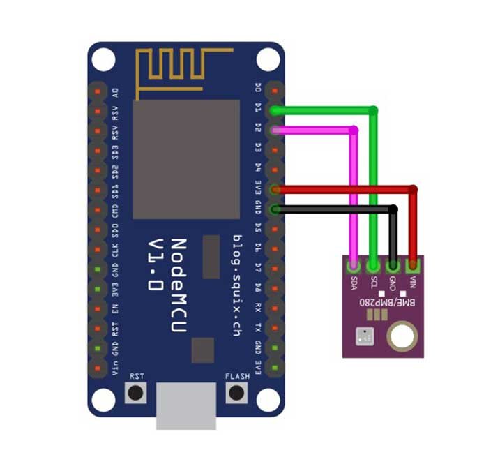
- Connect the VCC and GND pins of the BME280 sensor to the 3.3V and GND pins of the NodeMCU board, respectively.
- Connect the SDA and SCL pins of the BME280 sensor to the corresponding pins (D1 and D2) on the NodeMCU board, respectively.
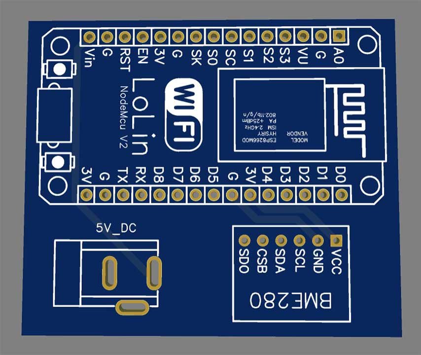
Project PCB Gerber File & PCB Ordering Online
For a more professional and compact setup, you can consider designing a custom PCB for this project. You can use online PCB fabrication services like PCBWay.com to create a custom PCB based on your circuit design. This will provide a neat and reliable solution for your Remote Sensor Monitoring.
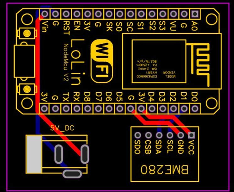
The Gerber File for the PCB is given below. You can simply download the Gerber File and order the PCB from PCBWay.com.
Now you can visit the PCBWay official website by clicking here: PCBWay.com. So you will be directed to the PCBWay website.
You can now upload the Gerber File to the Website and place an order. The PCB quality is superb & high standard. That is why most people trust PCBWay for PCB & PCBA Services. PCBWay is a leading manufacturer of high-quality PCBs and offers a wide range of services, including PCB fabrication, assembly, and components sourcing.
Arduino Source/Program Code
Below is the program code for setting up the remote serial monitor using WebSerial. We will go through the code explanation later in this blog post.
#include <ESP8266WiFi.h>
#include <ESPAsyncTCP.h>
#include <ESPAsyncWebServer.h>
#include <WebSerial.h>

#include <Wire.h>
#include <Adafruit_Sensor.h>
#include <Adafruit_BME280.h>
#define SEALEVELPRESSURE_HPA (1013.25)
Adafruit_BME280 bme; // For I2C interface

#define LED_GPIO 2  //D4
AsyncWebServer server(80);

const char* ssid = "IoT Projects Ideas"; // Your WiFi AP SSID
const char* password = "244466666"; // Your WiFi Password


/* Message callback of WebSerial */
void message(uint8_t *data, size_t len) {
  WebSerial.println("Data Received!");
  String Data = "";
  for (int i = 0; i < len; i++) {
    Data += char(data[i]);
  }
  WebSerial.println(Data);
  if (Data == "ON") {
    digitalWrite(LED_GPIO, LOW);
  }
  if (Data == "OFF") {
    digitalWrite(LED_GPIO, HIGH);
  }
}

void setup() {
  Serial.begin(115200);
  pinMode(LED_GPIO, OUTPUT);
  Serial.println(F("BME280 Sensor event test"));
  if (!bme.begin()) {
    Serial.println("Could not find a valid BME280 sensor, check wiring!");
    while (1);
  }

  WiFi.mode(WIFI_STA);
  WiFi.begin(ssid, password);
  if (WiFi.waitForConnectResult() != WL_CONNECTED) {
    Serial.printf("WiFi Failed!n");
    return;
  }
  Serial.print("IP Address: ");
  Serial.println(WiFi.localIP());

  WebSerial.begin(&server);
  WebSerial.msgCallback(message);
  server.begin();
}

void loop() {
  Serial.print("Temperature = ");
  Serial.print(bme.readTemperature());
  Serial.print(" °CttHumidity = ");
  Serial.print(bme.readHumidity());
  Serial.println(" %");

  Serial.print("Pressure = ");
  Serial.print(bme.readPressure() / 100.0F);
  Serial.print(" hPattApprox. Altitude = ");
  Serial.print(bme.readAltitude(SEALEVELPRESSURE_HPA));
  Serial.println(" m");
  Serial.println(); // Add an empty line

  WebSerial.print("Temperature = ");
  WebSerial.print(bme.readTemperature());
  WebSerial.println(" °C");

  WebSerial.print("Humidity = ");
  WebSerial.print(bme.readHumidity());
  WebSerial.println(" %");
  Serial.println(); // Add an empty line
  delay(2000);
}
Program Code Explanation
Include the required libraries for ESP8266, async TCP, web server, and WebSerial. Also, include the Wire library for I2C communication and the Adafruit sensor and BME280 libraries for the BME280 sensor.
#include <ESP8266WiFi.h>
#include <ESPAsyncTCP.h>
#include <ESPAsyncWebServer.h>
#include <WebSerial.h>
#include <Wire.h>
#include <Adafruit_Sensor.h>
#include <Adafruit_BME280.h>
Define the constant SEALEVELPRESSURE_HPA for altitude calculation and create an instance of the Adafruit_BME280 class for sensor communication.
#define SEALEVELPRESSURE_HPA (1013.25)
Adafruit_BME280 bme; // For I2C interface
Define the GPIO pin for the LED, which will be used to demonstrate remote control.
#define LED_GPIO 2 //D4
Initialize the web server at port 80
AsyncWebServer server(80);
Replace the SSID and Password with your Network credentials:
const char* ssid = "IoT Projects Ideas"; // Your WiFi AP SSID
const char* password = "244466666"; // Your WiFi Password
Check the message sent from WebSerial and control NodeMCU ESP8266 Builtin LED.
/* Message callback of WebSerial */
void message(uint8_t *data, size_t len) {
  WebSerial.println("Data Received!");
  String Data = "";
  for (int i = 0; i < len; i++) {
    Data += char(data[i]);
  }
  WebSerial.println(Data);
  if (Data == "ON") {
    digitalWrite(LED_GPIO, LOW);
  }
  if (Data == "OFF") {
    digitalWrite(LED_GPIO, HIGH);
  }
}
Initialize the serial communication at a baud rate of 115200. Set up the BME280 sensor. If the sensor is not found, an error message will be printed, and the program will halt.
  Serial.begin(115200);
  pinMode(LED_GPIO, OUTPUT);
  Serial.println(F("BME280 Sensor event test"));
  if (!bme.begin()) {
    Serial.println("Could not find a valid BME280 sensor, check wiring!");
    while (1);
  }
Configure the WiFi mode and connect to the specified WiFi network using the provided SSID and password.
  WiFi.mode(WIFI_STA);
  WiFi.begin(ssid, password);
  if (WiFi.waitForConnectResult() != WL_CONNECTED) {
    Serial.printf("WiFi Failed!n");
    return;
  }
  Serial.print("IP Address: ");
  Serial.println(WiFi.localIP());
Start the WebSerial communication and configure the message callback function to handle incoming messages from the web browser. Then Begin the webserver to serve the web pages and handle incoming requests.
  WebSerial.begin(&server);
  WebSerial.msgCallback(message);
  server.begin();
In the loop, it prints the Temperature, Humidity, Atmospheric Pressure, and Altitude on the serial monitor as well as on the WebSerial.
void loop() {
  Serial.print("Temperature = ");
  Serial.print(bme.readTemperature());
  Serial.print(" °CttHumidity = ");
  Serial.print(bme.readHumidity());
  Serial.println(" %");

  Serial.print("Pressure = ");
  Serial.print(bme.readPressure() / 100.0F);
  Serial.print(" hPattApprox. Altitude = ");
  Serial.print(bme.readAltitude(SEALEVELPRESSURE_HPA));
  Serial.println(" m");
  Serial.println(); // Add an empty line

  WebSerial.print("Temperature = ");
  WebSerial.print(bme.readTemperature());
  WebSerial.println(" °C");

  WebSerial.print("Humidity = ");
  WebSerial.print(bme.readHumidity());
  WebSerial.println(" %");
  Serial.println(); // Add an empty line
  delay(2000);
}
Demo and Testing: Remote Serial Monitor
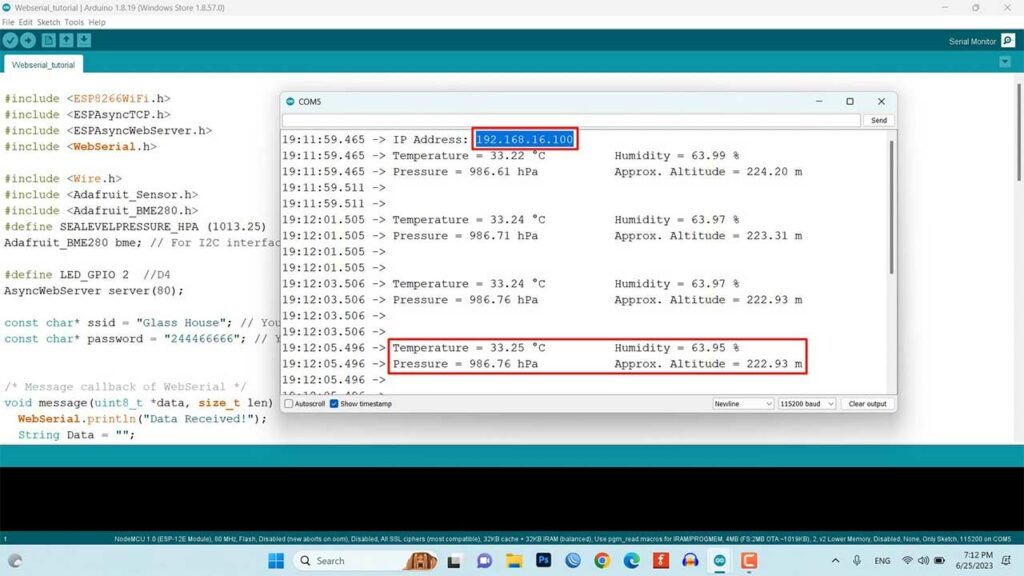
Once you have uploaded the code to the NodeMCU board, open the serial monitor to observe the sensor readings locally.
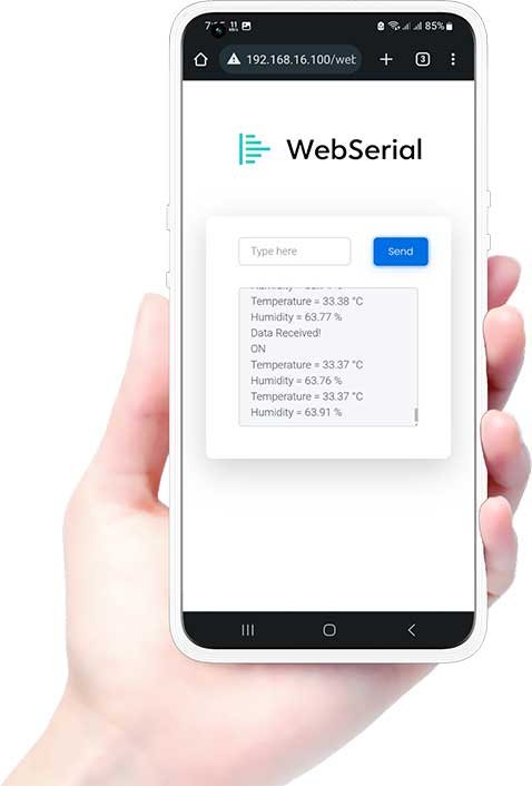
Additionally, To Access Webserial: Go to <IP Address>/webserial in your browser ( where <IP Address> is the IP of your ESP8266 board). You should see a web page displaying the temperature and humidity readings.
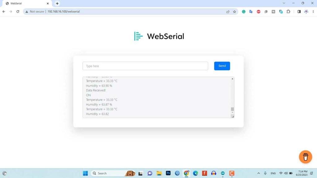
Try sending “ON” or “OFF” messages through the web page to control the LED connected to the GPIO pin. You will see the corresponding message and LED status change on the local serial monitor as well.
Conclusion
In this blog post, we explored creating a remote serial monitor for ESP8266 using WebSerial. We have learned about the components required, circuit connections, and the program code. By leveraging WebSerial, we can monitor and control our ESP8266 projects remotely through a web browser, providing a convenient way to interact with our devices. This opens up a wide range of possibilities for remote monitoring and automation applications.


Why do examples always add a bunch of unrelated complexity?
This article is supposed to be about ESP8266 WebSerial, why did you add all the code involving a pressure sensor?
Gerber files, PCBWay. distractions.
All that extra stuff makes it difficult for us newbies to isolate the parts we need.
Mark.