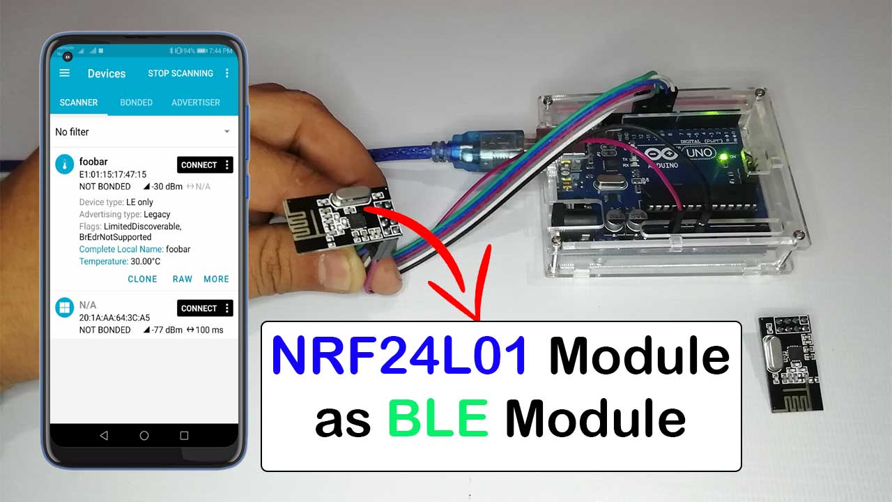
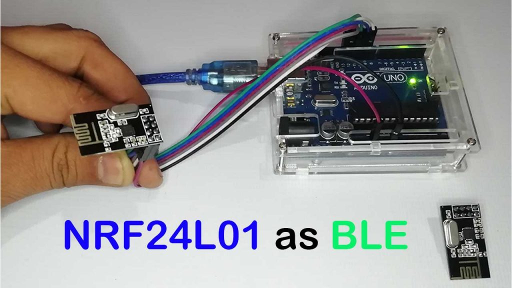
Today we will learn to use the NRF24L01 module as a BLE module with Arduino. Many times you may have come across that term called BLE, which stands for Bluetooth Low Energy, and it is basically a highly optimized version of Bluetooth. As we know that ESP32 comes with inbuilt, BLE capabilities. Here We have an NRF module in the market, which can be used as a BLE module.
It is significantly cheaper than the HM10 BLE module or ESP32. Yes. I am talking about the NRF24L01 RF module that can be used as a BLE module. Thus today in this tutorial, we will learn how to use an NRF as a BLE module with an Arduino. Without wasting any further time, let’s get into this.
Components Required
Recently, I came to know that NRF has BLE capabilities. Thus I thought to give this a try. Before we proceed with the building, make sure you have the following components:
| S.N | Components Name | Description | Quantity | |
|---|---|---|---|---|
| 1 | Arduino UNO | ARDUINO UNO R3 | 1 | https://amzn.to/2L0iZf2 |
| 2 | NRF Module | NRF24L01 Module | 2 | https://amzn.to/38M3eld |
| 3 | Jumper Wires | Jumper Cables breadboard friendly | 7 | https://amzn.to/2JWSR44 |
| 4 | USB Type B Cable | USB Cord Cable for Arduino UNO | 1 | https://amzn.to/362fmNx |
BLE is a smaller and highly optimized version of classic Bluetooth. Actually, BLE was designed by keeping in mind the lowest possible power consumptions, especially for low cost, low bandwidth, low power, and low complexity.
So, the BLE devices can run for a long period with just a coin cell.
Circuit Connection for NRF24L01 and Arduino
Before we proceed with the programming, let’s get into the circuit part. So please refer to the shown NRF24L01 and Arduino connections.
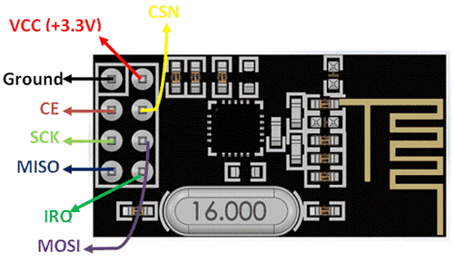
| S.N | NRF24L01 Module | Arduino UNO |
| 1 | VCC | 3.3V |
| 2 | GND | GND |
| 3 | CE | Pin 9 |
| 4 | SCN/CSN | Pin 10 |
| 5 | SCK | Pin 13 |
| 6 | MOSI | Pin 11 |
| 7 | MISO | Pin 12 |
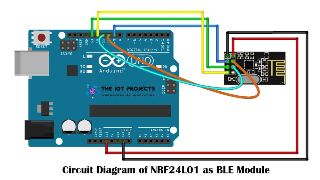
The NRF24L01 Module is not breadboard-friendly. So I recommend you use custom PCB for this project.
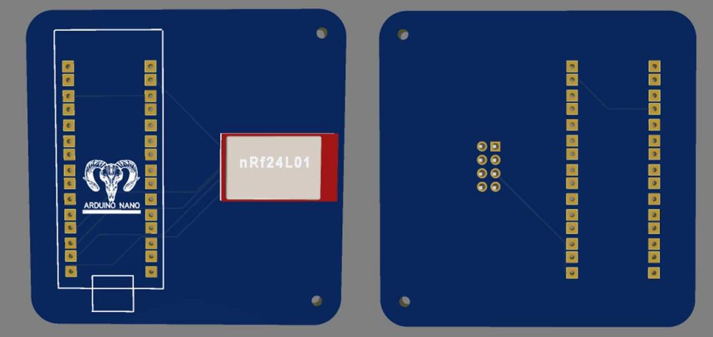
You can simply download the Gerber file and order the PCB from https://www.PCBWay.com at a cheap price.
PCBWay is quite professional in PCB manufacturing. You can try their services at extremely low prices. Only $5 for 10 PCBs and $30 in total for 20 PCBs assembly. Besides this, the new members also get a $5 sign-up bonus. That means the new users can order 10 PCBs for free.
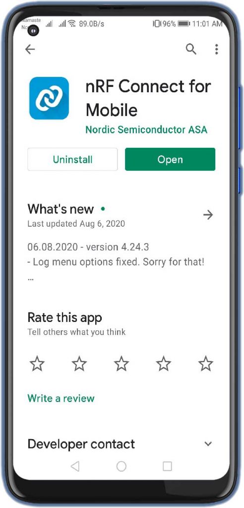
So, you need to connect NRF24L01 and Arduino pins accordingly. After going through connections, go to your smartphone and download NRF mobile applications from the play store. We use it for reading NRF data over the BLE on our smartphones.
Program NRF24L01 as BLE Module with Arduino
Today We are going to use the cheapest alternative NRF24L01 as BLE Module with Arduino. So let’s get into the PC to set up the Arduino microcontroller, to use this module.
Libraries for using NRF24L01 as BLE Module
Now open the Arduino IDE, again go to the library section of your Arduino IDE. And in order to use the NRF BLE capabilities, we need two libraries.
The first one is the NRF24 library for the NRF module. So you need to install this library. And again the second library for the BLE module is BTLE. So, install this library in your Arduino IDE.
So after installing the libraries, you can go to the example then BTLE and you can look at these examples: send, receive, and temperature.
SEND Example code for BLE
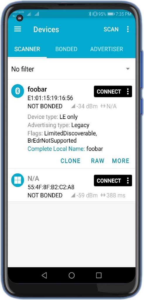
Now open the SEND example and upload this example code to our Arduino board. So we have uploaded the code and we should be able to observe the BLE device as “foobar”.
#include <SPI.h>
#include <RF24.h>
#include <BTLE.h>
RF24 radio(9,10);
BTLE btle(&radio);
void setup() {
Serial.begin(9600);
while (!Serial) { }
Serial.println("BTLE advertisement sender");
btle.begin("foobar");
}
void loop() {
btle.advertise(0,0);
btle.hopChannel();
Serial.print(".");
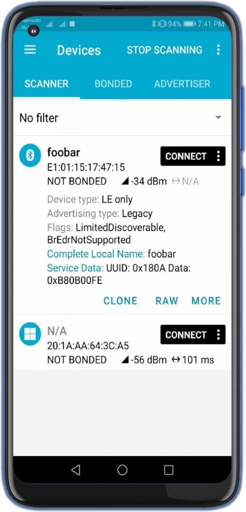
}Now let’s go to the NRF Connect mobile application. Here you can get the devices in the scanner section. If you don’t see your device, please refresh the page again. Now I hope you can see a device called “foobar”.
Now, this device is not sending any data. That’s because we are not sending any data in the program code. So in order to send data, we need to advertise the data using the “btle.advertise” command. And we need to put our data inside these parentheses().
btle.advertise(0,0);But, How? To add data, we need a variable buf of type “nrf_service.data”. and this variable can store two things, The first thing is UUID, which is Universal Unique Identifier used to identify the information in the computer systems. And the next thing it can store the float type of data.
So by default, this library can support three types of UUID and they all have their own purpose. NRF device information service UUID is used to advertise the device information. Then NRF Temperature Service UUID is used to advertise the Temperature. Then NRF battery service UUID is used to advertise the battery percentage.
Now in this send code. We will use these three types. So we can advertise these three types of data over the BLE with this BTLE library by default. But that does not mean you cannot create your own type of UUID and advertise the data. It is a different topic and we’ll make a video on that later.
NRF device information service UUID
Thus in a loop section let’s create a buf variable of NRF service data type, then we need to set the UUID type of the advertisement. So let’s copy all these three and we will first try NRF device information UUID. So let’s comment on the other two types. Now we need float data. So I created a float ’temp’ variable and we need to store the data of the ‘temp’ variable into the value variable of buf. But it has to be an NRF float type, not a normal Arduino float type. So this command will help us to Convert float to NRF float and then store it in the value variable of buf. Now, we need to put the advertising
void loop() {
float temp=0;
 nrf_service_data buf;
 buf.service_uuid = NRF_DEVICE_INFORMATION_SERVICE_UUID; //0x180A
 //buf.service_uuid = NRF_TEMPERATURE_SERVICE_UUID; //0x1809
 //buf.service_uuid =NRF_BATTERY_SERVICE_UUID; //0x180F
 buf.value = BTLE::to_nRF_Float(temp);
 btle.advertise(0x16, &buf, sizeof(buf));
 btle.hopChannel();
   btle.hopChannel();
   Serial.print(".");
   }
The command here, which contains the type of data, buf, and size of buf. Now, let’s upload the code to Arduino, and then let’s refresh our mobile app.
So here we are going to see our Foobar BLE device and in the service data part, we can see the UUID of our device.
NRF Temperature Service UUID
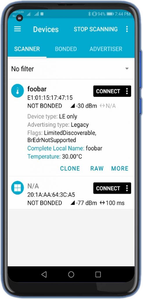
In the meantime let’s try the next UUID and it is NRF Temperature service UUID. So let’s uncomment this line and comment out the previous one and let’s consider, we want to send the temperature as 30 degrees celsius. So in the temp variable, I’ll put 30 values and upload the code. Similarly, refresh your app. Now we got the temperature icon here, and we can also see the temperature as 30 degrees Celsius.
void loop() {
float temp=30;
 nrf_service_data buf;
 //buf.service_uuid = NRF_DEVICE_INFORMATION_SERVICE_UUID; //0x180A
 buf.service_uuid = NRF_TEMPERATURE_SERVICE_UUID; //0x1809
 //buf.service_uuid =NRF_BATTERY_SERVICE_UUID; //0x180F
 buf.value = BTLE::to_nRF_Float(temp);
 btle.advertise(0x16, &buf, sizeof(buf));
 btle.hopChannel();
   btle.hopChannel();
   Serial.print(".");
   }
So similarly, instead of sending a fixed temperature data, we can attach a temperature sensor, and then we can send the real-time temperature data to our smartphone.
So if you want me to make a video on this topic, then let me know in the comment section below
The NRF Battery service UUID
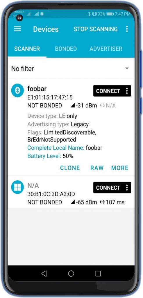
Now let’s comment on this and uncomment the NRF Battery service UUID. Before uploading the code. We needed some changes in the code. Change the float temp variable value to 0.5 Here it takes 1 as a maximum value which is 100% and for now, it shows 0.5 as a 50% battery level.
void loop() {
float temp=0.5;
 nrf_service_data buf;
 //buf.service_uuid = NRF_DEVICE_INFORMATION_SERVICE_UUID; //0x180A
 //buf.service_uuid = NRF_TEMPERATURE_SERVICE_UUID; //0x1809
 buf.service_uuid =NRF_BATTERY_SERVICE_UUID; //0x180F
 buf.value = BTLE::to_nRF_Float(temp);
 btle.advertise(0x16, &buf, sizeof(buf));
 btle.hopChannel();
   btle.hopChannel();
   Serial.print(".");
   }
Finally, upload the file to Arduino and refresh the App again. Here, we can see the battery percentage at 50%.
So, here we conclude the sending or advertising data part.
Receiver code for BLE to Advertise Data
Now let’s try this receiver code of BLE. Basically, what this code does is, it listens and receives all the data packets that are available near it. And it will print it on the serial monitor. But before that, we need to edit the hex part.
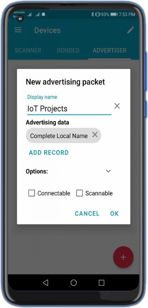
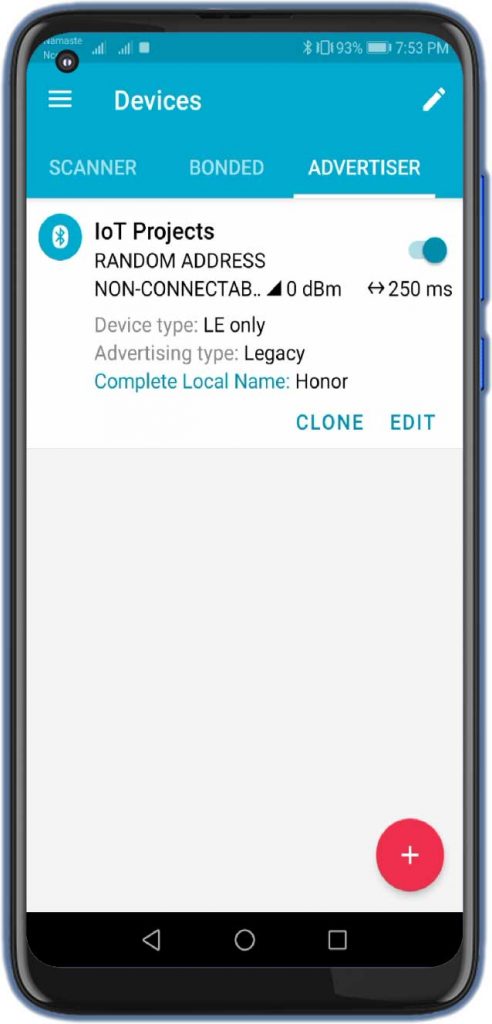
We need to typecast into the ‘char’ format. In order to decode the code into human-readable form. Now let’s upload the code to you. Arduino And open your app and then under the advertise section let’s create an advertisement. So just provide it with a name. Here I have provided it as the IoT Projects. then click on the add record and choose what you want to send.
#include <SPI.h>
#include <RF24.h>
#include <BTLE.h>
 RF24 radio(9,10);
 BTLE btle(&radio);
 void setup() {
 Serial.begin(9600);
   while (!Serial) { }
   Serial.println("BTLE advertisement receiver");
 btle.begin("");
 }
 void loop() {
 Serial.print("Listening… ");
 if (btle.listen()) {
     Serial.print("Got payload: ");
     for (uint8_t i = 0; i < (btle.buffer.pl_size)-6; i++) { Serial.print(char(btle.buffer.payload[i])); Serial.print(" "); }
   }
 Serial.println("done.");
   btle.hopChannel();
 }
I just want to advertise my device name. Which you can see on our screen. So after that, I will hit “ok“. And our advertisement is ready. Now Let’s turn it on, and open the serial monitor and you can see, we are receiving our device name in a readable form.
Video Tutorial: NRF24L01 module as BLE Module using Arduino
Conclusion
We can use these techniques to control any type of device by sending data, for example, lighting up your LED Bulb or even controlling AC home appliances. If you need an Article/video on that, let me know in the comments section. So, guys, that’s all about using NRF24L01 Module as BLE Module using Arduino. I hope you like this tutorial. If you did, give me a share from the share button below.
Recommended Readings:


How to create own tupe of uuid? Kindly help me
It’s one of those projects where you convince yourself you can’t do it. Your instructions were impeccable, I followed every step, and it works great. Thanks