Smart Activity Tracker using MPU6050 and Arduino
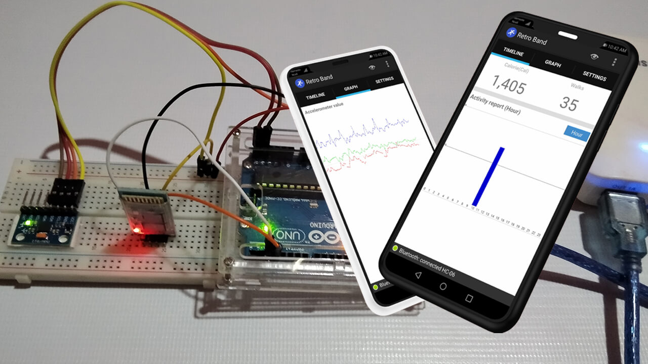
Today in this project we are going to assist you in making Smart Activity Tracker using MPU6050, Arduino, and HC-06 Bluetooth Module. This device is simple which connects to your mobile device with Bluetooth and track your daily routine. Like user’s steps, burned calories, etc on hourly/daily/monthly basis.
- Intro to Smart Activity Tracker
- Components Required
- Circuit Connection for Smart Activity Tracker
- Arduino source code for Smart Activity Tracker using MPU6050
- Retro Band Android App Compatibility
- Packaging
- Video Tutorial: Smart Activity Tracker using MPU6050 sensor, HC-06 Bluetooth Module, Arduino, and Android App
- Conclusion
Intro to Smart Activity Tracker
This project is not a “smart Band” since it has only simple features. So I called it an “Activity Tracker”. Actually, this is an Arduino wearable project is an open-source project. The Important thing about this activity tracker is we connect it with mobile devices by Bluetooth and track the daily routine of users.
This activity tracker runs with Arduino has only one feature. Actually, it is collecting data by using an accelerometer and sending them to the mobile device. Then the Retroband Mobile app calculates steps and calories from the data provided by the MPU6050 sensor. The feature of this device is simple, which means the structure of this device is also simple to understand. So, it’s very easy to make it to your own taste.
The retro band Android app checks steps using the collected data provided from activity tracker Arduino.
The algorithm of this app is not that complicated. If you have much experience in this area, you can replace it with your own algorithm. The app saves the calorie data, so you can see your progress on a monthly/daily/hourly basis from the graph.
Note: The Activity Tracker using Arduino cannot save the data itself. Since the shortage of Arduino memory capacity. This means we must connect the device with mobile to save the user data. i.e. you cannot collect the data with activity tracker band using Arduino only. I hope it will fix this problem when Arduino gets improved with higher storage capabilities.
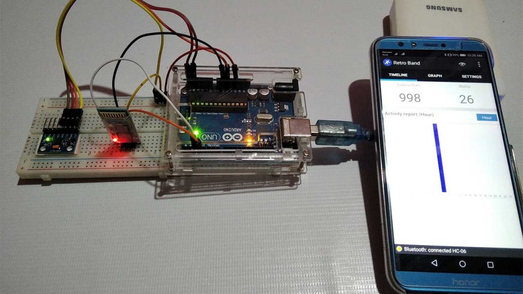
Components Required
This smart Activity Tracker Device works with the combination of the Arduino part and an Android app.
- The Arduino has 4 major parts
- Arduino board
- Gyro/Accelerometer(MPU-6050)
- Bluetooth module(HC-06) and
- Power source
- The Android app contains 4 parts
- Android UI
- Bluetooth manager
- Algorithm section and
- background service
When we power on the Arduino and pair the device with the RetroBand app. The algorithm on the Arduino checks the Accelerometer data 20 times in every 1 second. But it transfers the data to the mobile device once a second. The Android App receives the data from Arduino for two seconds and declares a user’s movement when movement detected. An increase in the user’s movement counted as the user’s step. Basically, this app also calculates burned calories based on the user’s weight and counted steps. The user can get the data on a monthly/daily/hourly basis through graphs.
If you want to buy parts which I used, refer to the below links.
| S.N | Components Name | Description | Quantity | |
|---|---|---|---|---|
| 1 | Arduino UNO | ARDUINO UNO R3 | 1 | https://amzn.to/2L0iZf2 |
| 2 | MPU6050 | MPU6050 6-axis Gyroscope/Accelerometer | 1 | https://amzn.to/39OEuKk |
| 3 | HC-06 Bluetooth | Arduino Wireless Bluetooth Transceiver Module Slave 4Pin Serial | 1 | https://amzn.to/3ovxu9B |
| 4 | Battery | 3.7V 1000mAh Lithium-Ion Battery | 1 | https://amzn.to/34ulkWl |
| 5 | Jumper Wires | Jumper Cables breadboard friendly | 8 | https://amzn.to/2JWSR44 |
This project is just a prototype, So I assemble the circuit on a breadboard. Alternatively, you can use any portable Arduino board like Arduino Nano or Arduino Pro Mini.
Circuit Connection for Smart Activity Tracker
The circuit connection for smart activity tracker using Arduino, MPU6050, and HC-06 Bluetooth module is very simple. Usually, you can go with the steps below for assembly.
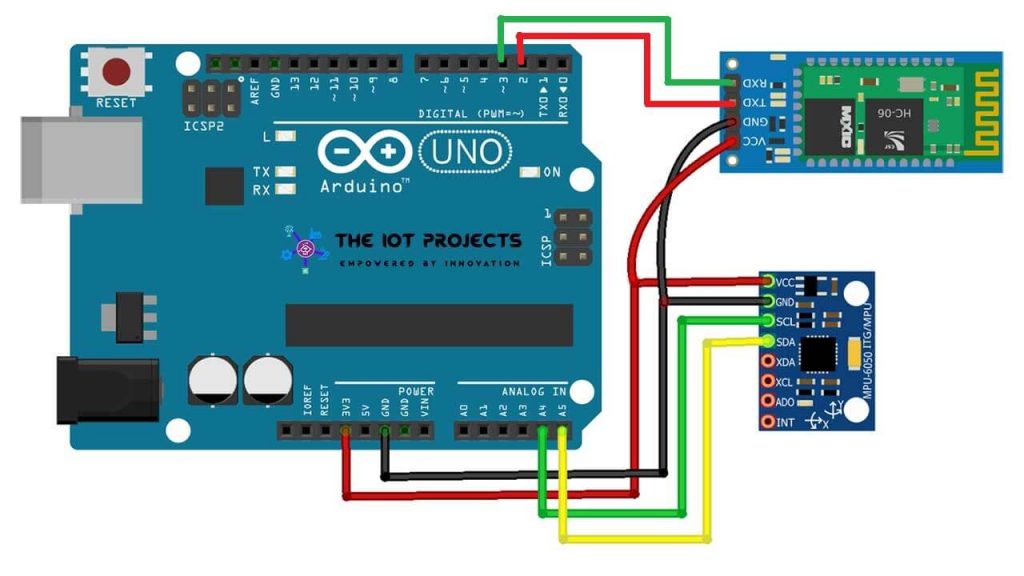
Connecting Arduino-Bluetooth module
You just connect VCC, GND, TXD, RXD pin as the module in the instruction (VCC->3.3v, GND->GND, TX->D2, RX->D3). The Bluetooth module wouldn’t work well if it touches other conducting objects or antennas, So, you need to solder all the modules very carefully if you are using the module without a breadboard. Once the module works okay after soldering, you need to fix it with a glue gun.
Connecting Arduino-Accelerometer(MPU-6050)
An accelerometer module uses an I2C interface. If you need an explanation about the I2C interface, click here. You don’t need to know more about the I2C interface in this project. The only thing that you need to know is the module gets the power through VCC(+), GND(-) pins, and transfers the data through SCL and SDA pins that are connected to A5 and A4 pin of Arduino.
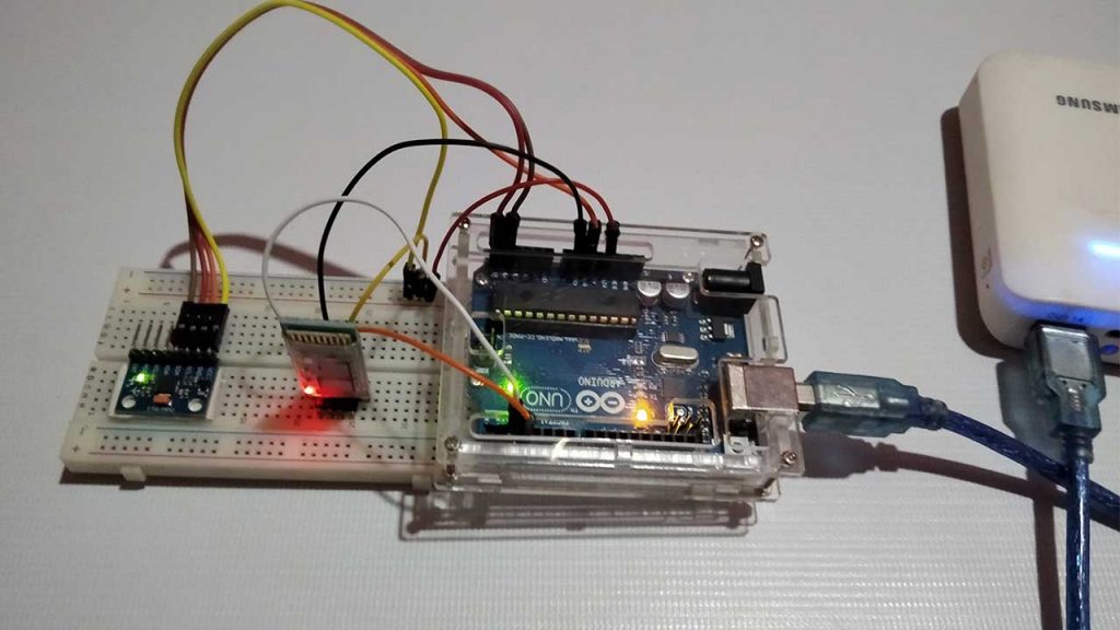
If you’ve got through all this process, it should be as below.
Arduino source code for Smart Activity Tracker using MPU6050
You can download Sketch(Arduino source code for Smart Activity Tracker) on GitHub. Download from the link below
#include <math.h>
#include <Wire.h>
#include <SoftwareSerial.h>
 /* Bluetooth */
 SoftwareSerial BTSerial(2, 3); //Connect HC-06. Use your (TX, RX) settings
 /* time */
 define SENDING_INTERVAL 1000
 define SENSOR_READ_INTERVAL 50
 unsigned long prevSensoredTime = 0;
 unsigned long curSensoredTime = 0;
 /* Data buffer */
 define ACCEL_BUFFER_COUNT 125
 byte aAccelBuffer[ACCEL_BUFFER_COUNT];
 int iAccelIndex = 2;
 /* MPU-6050 sensor */
 define MPU6050_ACCEL_XOUT_H 0x3B // R
 define MPU6050_PWR_MGMT_1 0x6B // R/W
 define MPU6050_PWR_MGMT_2 0x6C // R/W
 define MPU6050_WHO_AM_I 0x75 // R
 define MPU6050_I2C_ADDRESS 0x68
 typedef union accel_t_gyro_union {
     struct {
         uint8_t x_accel_h;
         uint8_t x_accel_l;
         uint8_t y_accel_h;
         uint8_t y_accel_l;
         uint8_t z_accel_h;
         uint8_t z_accel_l;
         uint8_t t_h;
         uint8_t t_l;
         uint8_t x_gyro_h;
         uint8_t x_gyro_l;
         uint8_t y_gyro_h;
         uint8_t y_gyro_l;
         uint8_t z_gyro_h;
         uint8_t z_gyro_l;
     } reg;
 struct {     int x_accel;     int y_accel;     int z_accel;     int temperature;     int x_gyro;     int y_gyro;     int z_gyro; } value;
 };
 void setup() {
     int error;
     uint8_t c;
 Serial.begin(9600); Wire.begin(); BTSerial.begin(9600);  // set the data rate for the BT port // default at power-up: // Gyro at 250 degrees second // Acceleration at 2g // Clock source at internal 8MHz // The device is in sleep mode. // error = MPU6050_read (MPU6050_WHO_AM_I, &c, 1); Serial.print(F("WHO_AM_I : ")); Serial.print(c,HEX); Serial.print(F(", error = ")); Serial.println(error,DEC); // According to the datasheet, the 'sleep' bit // should read a '1'. But I read a '0'. // That bit has to be cleared, since the sensor // is in sleep mode at power-up. Even if the // bit reads '0'. error = MPU6050_read (MPU6050_PWR_MGMT_2, &c, 1); Serial.print(F("PWR_MGMT_2 : ")); Serial.print(c,HEX); Serial.print(F(", error = ")); Serial.println(error,DEC); // Clear the 'sleep' bit to start the sensor. MPU6050_write_reg (MPU6050_PWR_MGMT_1, 0); initBuffer();
 }
 void loop() {
   curSensoredTime = millis();
 // Read from sensor
   if(curSensoredTime - prevSensoredTime > SENSOR_READ_INTERVAL) {
     readFromSensor();  // Read from sensor
     prevSensoredTime = curSensoredTime;
 // Send buffer data to remote if(iAccelIndex >= ACCEL_BUFFER_COUNT - 3) {   sendToRemote();   initBuffer();   Serial.println("------------- Send 20 accel data to remote"); }
 }
 }
 /
 BT Transaction
 /
 void sendToRemote() {
 // Write gabage bytes
 BTSerial.write( "accel" );
 // Write accel data
 BTSerial.write( (char*)aAccelBuffer );
 // Flush buffer
 //BTSerial.flush();
 }
 /
 Read data from the sensor and save it
 /
 void readFromSensor() {
 int error;
 double dT;
 accel_t_gyro_union accel_t_gyro;
 error = MPU6050_read (MPU6050_ACCEL_XOUT_H, (uint8_t *) &accel_t_gyro, sizeof(accel_t_gyro));
 if(error != 0) {
 Serial.print(F("Read accel, temp and gyro, error = "));
 Serial.println(error,DEC);
 }
 // Swap all high and low bytes.
 // After this, the registers values are swapped,
 // so the structure name like x_accel_l does no
 // longer contain the lower byte.
 uint8_t swap;
 define SWAP(x,y) swap = x; x = y; y = swap
 SWAP (accel_t_gyro.reg.x_accel_h, accel_t_gyro.reg.x_accel_l);
 SWAP (accel_t_gyro.reg.y_accel_h, accel_t_gyro.reg.y_accel_l);
 SWAP (accel_t_gyro.reg.z_accel_h, accel_t_gyro.reg.z_accel_l);
 SWAP (accel_t_gyro.reg.t_h, accel_t_gyro.reg.t_l);
 SWAP (accel_t_gyro.reg.x_gyro_h, accel_t_gyro.reg.x_gyro_l);
 SWAP (accel_t_gyro.reg.y_gyro_h, accel_t_gyro.reg.y_gyro_l);
 SWAP (accel_t_gyro.reg.z_gyro_h, accel_t_gyro.reg.z_gyro_l);
 // Print the raw acceleration values
 Serial.print(F("accel x,y,z: "));
 Serial.print(accel_t_gyro.value.x_accel, DEC);
 Serial.print(F(", "));
 Serial.print(accel_t_gyro.value.y_accel, DEC);
 Serial.print(F(", "));
 Serial.print(accel_t_gyro.value.z_accel, DEC);
 Serial.print(F(", at "));
 Serial.print(iAccelIndex);
 Serial.println(F(""));
 if(iAccelIndex < ACCEL_BUFFER_COUNT && iAccelIndex > 1) {
 int tempX = accel_t_gyro.value.x_accel;
 int tempY = accel_t_gyro.value.y_accel;
 int tempZ = accel_t_gyro.value.z_accel;
 /*
 // Check min, max value
 if(tempX > 16380) tempX = 16380;
 if(tempY > 16380) tempY = 16380;
 if(tempZ > 16380) tempZ = 16380;
 if(tempX < -16380) tempX = -16380;
 if(tempY < -16380) tempY = -16380;
 if(tempZ < -16380) tempZ = -16380;
 // We dont use negative value
 tempX += 16380;
 tempY += 16380;
 tempZ += 16380;
 */
 char temp = (char)(tempX >> 8);
 if(temp == 0x00)
   temp = 0x7f;
 aAccelBuffer[iAccelIndex] = temp;
 iAccelIndex++;
 temp = (char)(tempX);
 if(temp == 0x00)
   temp = 0x01;
 aAccelBuffer[iAccelIndex] = temp;
 iAccelIndex++;
 temp = (char)(tempY >> 8);
 if(temp == 0x00)
   temp = 0x7f;
 aAccelBuffer[iAccelIndex] = temp;
 iAccelIndex++;
 temp = (char)(tempY);
 if(temp == 0x00)
   temp = 0x01;
 aAccelBuffer[iAccelIndex] = temp;
 iAccelIndex++;
 temp = (char)(tempZ >> 8);
 if(temp == 0x00)
   temp = 0x7f;
 aAccelBuffer[iAccelIndex] = temp;
 iAccelIndex++;
 temp = (char)(tempZ);
 if(temp == 0x00)
   temp = 0x01;
 aAccelBuffer[iAccelIndex] = temp;
 iAccelIndex++;
 }
 // The temperature sensor is -40 to +85 degrees Celsius.
 // It is a signed integer.
 // According to the datasheet:
 // 340 per degrees Celsius, -512 at 35 degrees.
 // At 0 degrees: -512 - (340 * 35) = -12412
 //  Serial.print(F("temperature: "));
 //  dT = ( (double) accel_t_gyro.value.temperature + 12412.0) / 340.0;
 //  Serial.print(dT, 3);
 //  Serial.print(F(" degrees Celsius"));
 //  Serial.println(F(""));
 // Print the raw gyro values.
 //  Serial.print(F("gyro x,y,z : "));
 //  Serial.print(accel_t_gyro.value.x_gyro, DEC);
 //  Serial.print(F(", "));
 //  Serial.print(accel_t_gyro.value.y_gyro, DEC);
 //  Serial.print(F(", "));
 //  Serial.print(accel_t_gyro.value.z_gyro, DEC);
 //  Serial.println(F(""));
 }
 /
 MPU-6050 Sensor read/write
 /
 int MPU6050_read(int start, uint8_t *buffer, int size)
 {
 int i, n, error;
 Wire.beginTransmission(MPU6050_I2C_ADDRESS);
 n = Wire.write(start);
 if (n != 1)
     return (-10);
 n = Wire.endTransmission(false); // hold the I2C-bus
 if (n != 0)
     return (n);
 // Third parameter is true: relase I2C-bus after data is read.
 Wire.requestFrom(MPU6050_I2C_ADDRESS, size, true);
 i = 0;
 while(Wire.available() && i<size)
 {
     buffer[i++]=Wire.read();
 }
 if ( i != size)
     return (-11);
 return (0); // return : no error
 }
 int MPU6050_write(int start, const uint8_t *pData, int size)
 {
     int n, error;
 Wire.beginTransmission(MPU6050_I2C_ADDRESS); n = Wire.write(start); // write the start address if (n != 1)     return (-20); n = Wire.write(pData, size); // write data bytes if (n != size)     return (-21); error = Wire.endTransmission(true); // release the I2C-bus if (error != 0)     return (error); return (0); // return : no error
 }
 int MPU6050_write_reg(int reg, uint8_t data)
 {
     int error;
     error = MPU6050_write(reg, &data, 1);
     return (error);
 }
 /
 Utilities
 /
 void initBuffer() {
 iAccelIndex = 2;
 for(int i=iAccelIndex; i<ACCEL_BUFFER_COUNT; i++) {
 aAccelBuffer[i] = 0x00;
 }
 aAccelBuffer[0] = 0xfe;
 aAccelBuffer[1] = 0xfd;
 aAccelBuffer[122] = 0xfd;
 aAccelBuffer[123] = 0xfe;
 aAccelBuffer[124] = 0x00;
 }
Compile Arduino source code
You need 3 working libraries in order to compile Arduino source code for smart Activity Tracker.
#include <math.h>
#include <Wire.h>
#include <SoftwareSerial.h>
Math.h library function for calculation. Wire.h function for I2C communication with the Gyroscope/Accelerometer MPU6050 Sensor. Finally, SoftwareSerial.h function for serial communication with the HC-06 Bluetooth module. Actually, by default Arduino IDE support these libraries.
Now, Click on the compile button on Arduino IDE. If you see the result ‘OK’, then you can proceed with the uploading process.
Uploading Arduino source
You need to upload the Smart Activity Tracker Arduino source code on the Arduino board after compiling the code. Before you upload it, select board type “Arduino UNO” and its “COM Port” from Tools Menu.
Some common errors while uploading the code.
- The board that you choose on Arduino IDE is different.
- Serial pins TX and RX are not in order as they should be.
- The bootloader on the board is malfunctioning.
Retro Band Android App Compatibility
The Android app for Retro Band is compatible with Android 4.0+. If you are using an Android device, which Android version is less than 4.0. Also, for an iPhone user, the app is only for Android users.
This is too vast to describe how to compile Android source code and change it, so I won’t cover it. But you can easily download the retro band Android source code on GitHub. Just make sure you have protected the copyright statement.
You can download the Retro Band app from the link provided below: The app is no more on PlayStore.
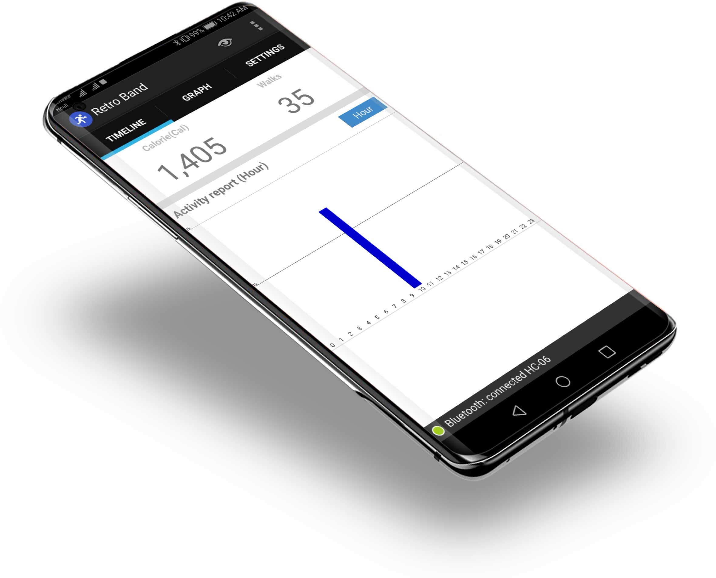
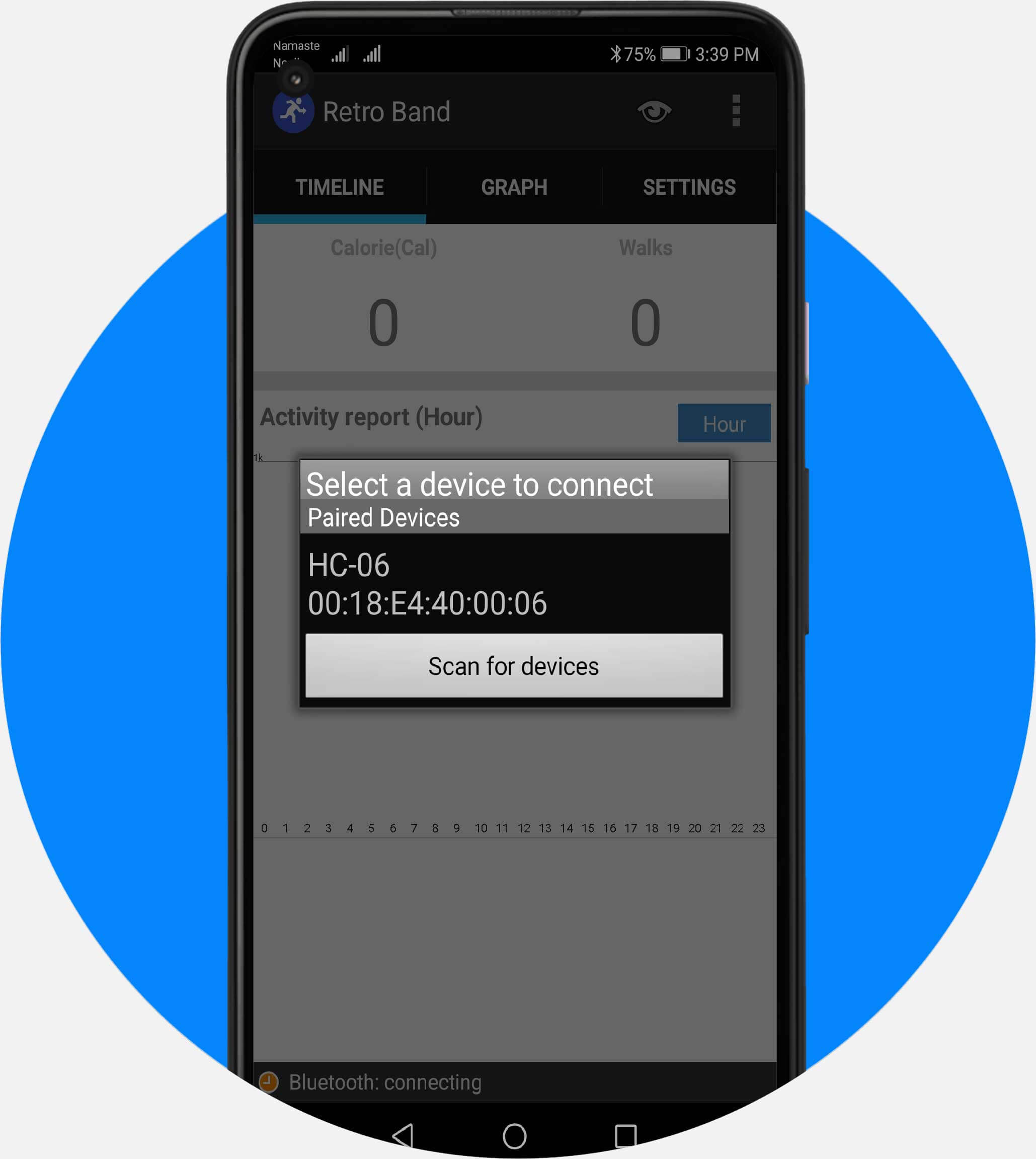
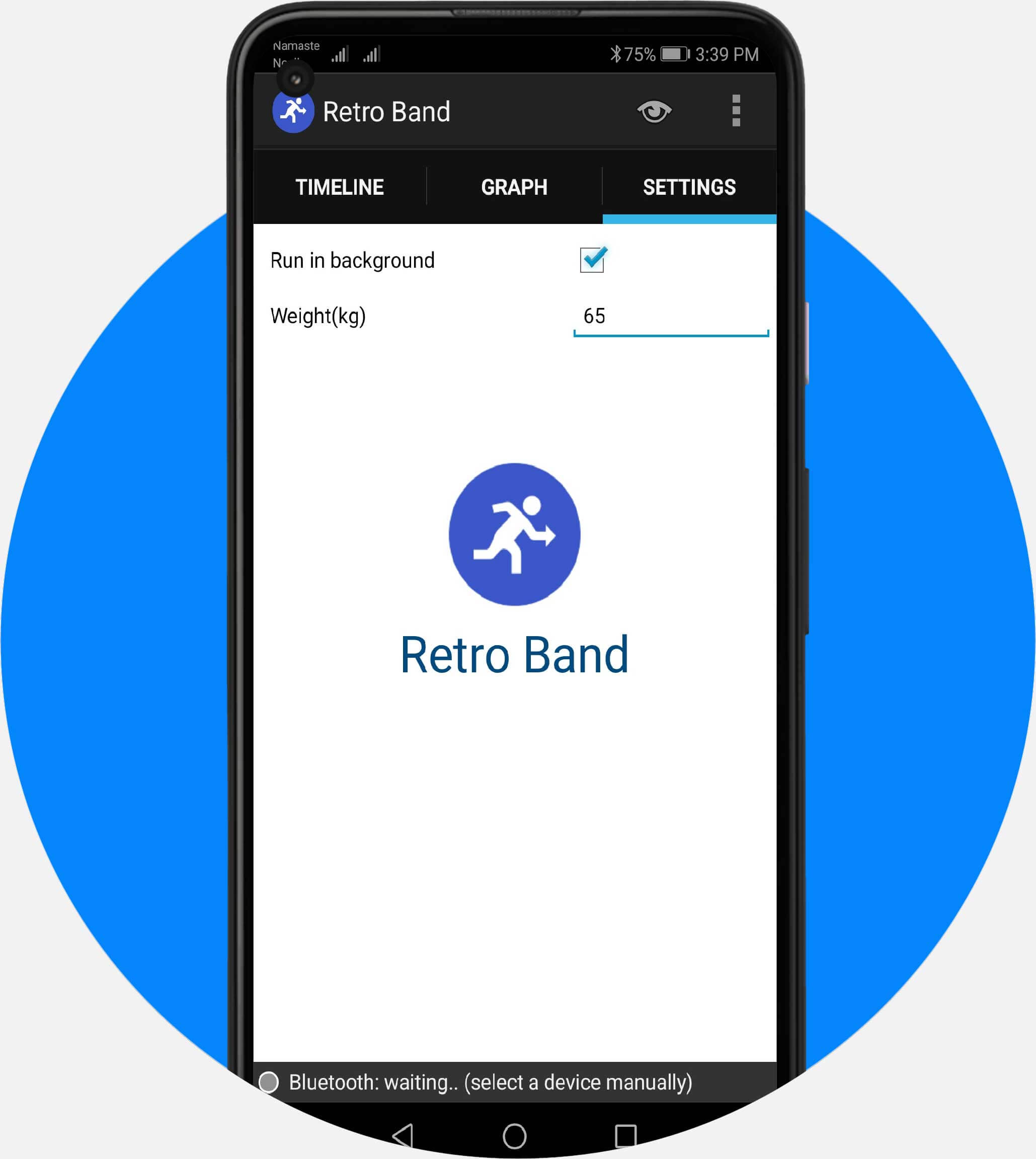
If you install the app, run it, and pair the mobile device with a retro band to get the app data successfully. The app has 3 menu tabs.
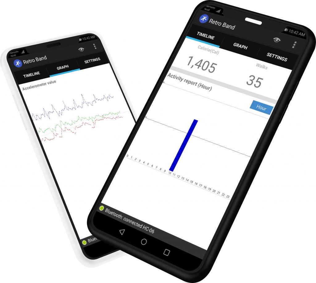
- Timeline: It collects calorie data burned every hour. You can check how many hours you have burned per hour/daily/monthly.
- Graph: This shows the graph using data sent by Arduino. You can see how the 3-axis value changes.
- Settings: You can configure the app settings here, and input your weight here.
Packaging
If you have a 3D printer, try making your own case. What you see in the picture below is a case made by a 3D printer, which embeds every module except the recharging module and can be worn as a wrist band.
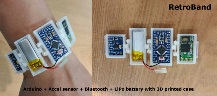
Special thanks to Chang-Han Jeon, Wired Factory team(Il-Yong Park, Byung-Gyu Kim, KyungReol Ku, Sang-Won Lee, Kyung-Bu Jeong)
Video Tutorial: Smart Activity Tracker using MPU6050 sensor, HC-06 Bluetooth Module, Arduino, and Android App
Conclusion
So this is how we made a smart Activity Tracker Band using Arduino, MPU6050, HC-06 Bluetooth Module, and Retro Band Mobile App. I hope you love this project. we also have few more projects based on MPU6050 Gyro/Accelerometer sensor check them out:

Hello. Can we use HC05 Bluetooth module instead of HC06? Is there necessary code change for HC05?
No you can’t
Could you modify your code for HC-05 please? I have HC-05 and I have to prepare my project in five days. If you do, is save my life. Please…..